Cisco M390 Content Security Management Appliance
Available Models
The M390 SMA is available in the following models:
- M390—Six 600-GB hard disk drives
- M390X—Eight 600-GB hard disk drives
Rear Panel Ports
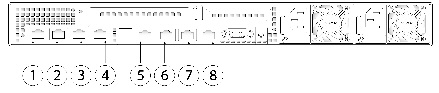
Figure 6-1 shows the rear panel ports of the Cisco M390 Content Security Management Appliance.
Figure 6-1 Cisco M390 Content Security Management Appliance Rear Panel Ports
|
|
Data 1 Gigabit Ethernet customer data interface |
|
Data 2 Gigabit Ethernet customer data interface |
|
|
Data 3 Gigabit Ethernet customer data interface |
|
Data 4 Gigabit Ethernet customer data interface |
|
|
RPC port The RPC port speed is configured statically to 100 mbps and full-duplex mode without autonegotiation. Without autonegotiation, the RPC port fails to connect properly and cannot be used. |
|
Console port Directly connects a computer to the appliance |
|
|
Data 5 Gigabit Ethernet customer data interface |
|
Management interface Gigabit Ethernet interface restricted to management use only |
Using Status LEDs and Buttons for Maintenance
This section describes the location and meaning of LEDs and buttons and includes the following topics:
Front Panel LEDs
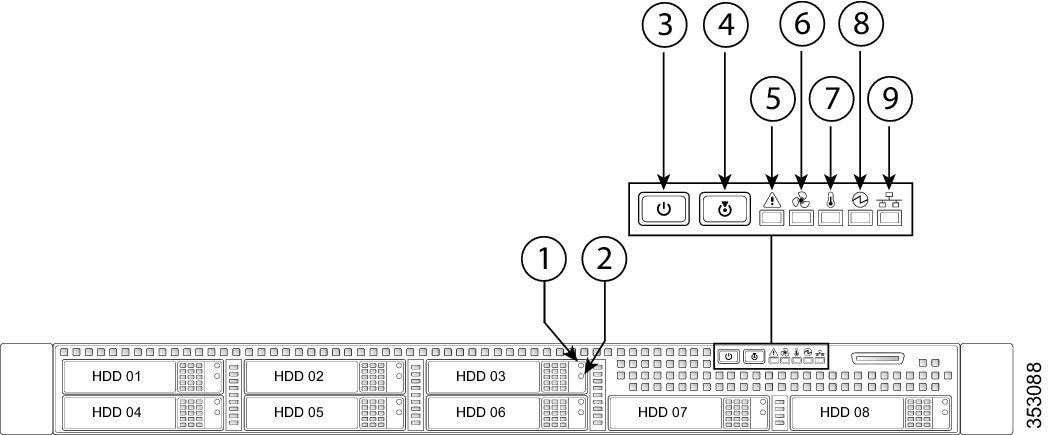
Figure 6-2 shows the front panel LEDs for the M390X model, with eight disk drives. Table 6-1 defines the LED states.
Figure 6-2 Cisco M390 Content Security Management Appliance Front Panel LEDs
|
|
Hard drive fault LED |
|
Fan status LED |
|
|
Hard drive activity LED |
|
Temperature status LED |
|
|
Power button/power status LED |
|
Power supply status LED |
|
|
Identification button/LED |
|
Network link activity LED |
|
|
System status LED |
|
|
Table 6-1 Front Panel LEDs, Definitions of States
|
|
|
1 |
Hard drive fault |
- Off—The hard drive is operating properly.
- Amber—Drive fault detected.
- Amber, flashing—The device is rebuilding.
- Amber, flashing with one-second interval—Drive locate function activated.
|
2 |
Hard drive activity |
- Off—There is no hard drive in the hard drive tray (no access, no fault).
- Green—The hard drive is ready.
- Green, flashing—The hard drive is reading or writing data.
|
3 |
Power button/LED |
- Off—There is no AC power to the appliance.
- Amber—The appliance is in standby power mode. Power is supplied only to the Baseboard Management Controller (BMC) and some motherboard functions which enable you to use remote power commands.
- Green—The appliance is in main power mode. Power is supplied to all appliance components.
|
4 |
Unit identification |
- Off—The unit identification function is not in use.
- Blue—The unit identification function is activated.
|
5 |
System status |
- Green—The appliance is running in normal operating condition.
- Green, flashing—The appliance is performing system initialization and memory check.
- Amber—The appliance is in a degraded operational state. For example:
– Power supply redundancy is lost. Power supply redundancy is lost. – CPUs are mismatched. – At least one CPU is faulty. – At least one DIMM is faulty. – At least one drive in a RAID configuration failed.
- Amber, flashing—The appliance is in a critical fault state. For example:
– Boot failed. – Fatal CPU and/or bus error is detected. – The appliance is in an over-temperature condition. |
6 |
Fan status |
- Green—All fan modules are operating properly.
- Amber—One or more fan modules breached the critical threshold.
- Amber, flashing—One or more fan modules breached the non-recoverable threshold.
|
7 |
Temperature status |
- Green—The appliance is operating at normal temperature.
- Amber—One or more temperature sensors breached the critical threshold.
- Amber, flashing—One or more temperature sensors breached the non-recoverable threshold.
|
8 |
Power supply status |
- Green—All power supplies are operating normally.
- Amber—One or more power supplies are in a degraded operational state.
- Amber, flashing—One or more power supplies are in a critical fault state.
|
9 |
Network link activity |
- Off—The Ethernet link is idle.
- Green—One or more Ethernet LOM ports are link-active, but there is no activity.
- Green, flashing—One or more Ethernet LOM ports are link-active, with activity.
|
Rear Panel LEDs and Buttons
The rear panel has the following LEDs and buttons that can be used to maintain the appliance:
- Power supply AC status LED—Located on the bottom left of each power supply.
- Data/management port link speed LED—Located to the left of each data or management port.
- Data/management port link status LED—Located to the right of each data or management port.
- Unit identification button/LED—Located to the right of the VGA video port (DB-15).
Table 6-2 defines the LED states.
Table 6-2 Rear Panel LEDs, Definitions of States
|
|
|
Power supply status |
- Off—No AC input (12 V main power off, 12 V standby power off).
- Green, flashing—12 V main power off; 12 V standby power on.
- Green—12 V main power on; 12 V standby power on.
- Amber, flashing—Warning detected but 12 V main power on.
- Amber—Critical error detected; 12 V main power off.
|
Data/Management port link speed |
- Off—Link speed is 10 Mbps.
- Amber—Link speed is 100 Mbps.
- Green—Link speed is 1 Gbps.
|
Data/Management port link status |
- Off—No link is present.
- Green—Link is active.
- Green, flashing—Traffic is present on the active link.
|
Rear unit identification |
- Off—The unit identification LED is not in use.
- Blue—The unit identification LED is activated.
|
Summary of Features
Table 6-3 lists the features of the M390 Content Security Management Appliance.
.
Table 6-3 Cisco M390 Content Security Management Appliance Features
|
|
|
Chassis |
One rack-unit (1RU) chassis |
Processors |
Two E5–2620 v3 processor |
Memory |
Two 8-GB DDR4-2133 DIMMs |
RPC |
Accessed through the 1-Gb dedicated port The RPC port speed is configured statically to 100 mbps and full-duplex mode without autonegotiation. Without autonegotiation, the RPC port fails to connect properly and cannot be used. |
Data ports |
Five 1-Gb BASE-T Ethernet LAN ports |
Management I/O |
Supported connectors:
- One 1-Gb BASE-T Ethernet LAN ports
- One RS-232 serial port
|
Power |
Two 770 W AC power supplies |
Power consumption |
2626 BTU/hr |
Cooling |
Six fan modules for front-to-rear cooling |
Storage |
Six or eight 600 GB hard disk drives (2.5” 10K SAS 4Kn) are installed into front-panel drive bays that provide hot-swappable access for SAS drives. Note The drives with the PID CCS-HDD-600GB-RV-A are 1.8 TB, but have been partitioned to 600 GB of usable space. |
Disk management
(RAID) |
Dedicated internal riser for a PCIe-style Cisco modular RAID controller card |
 フィードバック