ASDM Book 1: Cisco ASA Series General Operations ASDM Configuration Guide, 7.2
Bias-Free Language
The documentation set for this product strives to use bias-free language. For the purposes of this documentation set, bias-free is defined as language that does not imply discrimination based on age, disability, gender, racial identity, ethnic identity, sexual orientation, socioeconomic status, and intersectionality. Exceptions may be present in the documentation due to language that is hardcoded in the user interfaces of the product software, language used based on RFP documentation, or language that is used by a referenced third-party product. Learn more about how Cisco is using Inclusive Language.
- Updated:
- March 18, 2014
Chapter: Failover
- Introduction to Failover
- Failover Overview
- Failover System Requirements
- Failover and Stateful Failover Links
- MAC Addresses and IP Addresses
- Intra- and Inter-Chassis Module Placement for the ASA Services Module
- Stateless and Stateful Failover
- Transparent Firewall Mode Requirements
- Failover Health Monitoring
- Failover Times
- Configuration Synchronization
- Information About Active/Standby Failover
- Information About Active/Active Failover
Failover
This chapter describes how to configure Active/Standby or Active/Active failover, and includes the following sections:
- Introduction to Failover
- Licensing Requirements Failover
- Prerequisites for Failover
- Guidelines and Limitations
- Default Settings
- Configuring Active/Standby Failover
- Configuring Active/Active Failover
- Configuring Optional Failover Parameters
- Managing Failover
- Monitoring Failover
- Feature History for Failover
Introduction to Failover
- Failover Overview
- Failover System Requirements
- Failover and Stateful Failover Links
- MAC Addresses and IP Addresses
- Intra- and Inter-Chassis Module Placement for the ASA Services Module
- Stateless and Stateful Failover
- Transparent Firewall Mode Requirements
- Failover Health Monitoring
- Failover Times
- Configuration Synchronization
- Information About Active/Standby Failover
- Information About Active/Active Failover
Failover Overview
Configuring failover requires two identical ASAs connected to each other through a dedicated failover link and, optionally, a state link. The health of the active units and interfaces is monitored to determine if specific failover conditions are met. If those conditions are met, failover occurs.
The ASA supports two failover modes, Active/Active failover and Active/Standby failover. Each failover mode has its own method for determining and performing failover.
- In Active/Standby failover, one unit is the active unit. It passes traffic. The standby unit does not actively pass traffic. When a failover occurs, the active unit fails over to the standby unit, which then becomes active. You can use Active/Standby failover for ASAs in single or multiple context mode.
- In an Active/Active failover configuration, both ASAs can pass network traffic. Active/Active failover is only available to ASAs in multiple context mode. In Active/Active failover, you divide the security contexts on the ASA into 2 failover groups. A failover group is simply a logical group of one or more security contexts. One group is assigned to be active on the primary ASA, and the other group is assigned to be active on the secondary ASA. When a failover occurs, it occurs at the failover group level.
Failover System Requirements
This section describes the hardware, software, and license requirements for ASAs in a failover configuration.
Hardware Requirements
The two units in a failover configuration must:
- Be the same model.
- Have the same number and types of interfaces.
- Have the same modules installed (if any)
- Have the same RAM installed.
If you are using units with different flash memory sizes in your failover configuration, make sure the unit with the smaller flash memory has enough space to accommodate the software image files and the configuration files. If it does not, configuration synchronization from the unit with the larger flash memory to the unit with the smaller flash memory will fail.
Software Requirements
The two units in a failover configuration must:
- Be in the same firewall mode (routed or transparent).
- Be in the same context mode (single or multiple).
- Have the same major (first number) and minor (second number) software version. However, you can temporarily use different versions of the software during an upgrade process; for example, you can upgrade one unit from Version 8.3(1) to Version 8.3(2) and have failover remain active. We recommend upgrading both units to the same version to ensure long-term compatibility.
See Upgrade a Failover Pair or ASA Cluster for more information about upgrading the software on a failover pair.
- Have the same AnyConnect images. If the failover pair has mismatched images when a hitless upgrade is performed, then the clientless SSL VPN connection terminates in the final reboot step of the upgrade process, the database shows an orphaned session, and the IP pool shows that the IP address assigned to the client is “in use.”
License Requirements
The two units in a failover configuration do not need to have identical licenses; the licenses combine to make a failover cluster license. See Failover or ASA Cluster Licenses for more information.
Failover and Stateful Failover Links
The failover link and the optional Stateful Failover link are dedicated connections between the two units.

Failover Link
The two units in a failover pair constantly communicate over a failover link to determine the operating status of each unit.
Failover Link Data
The following information is communicated over the failover link:
Interface for the Failover Link
You can use any unused interface (physical, redundant, or EtherChannel) as the failover link; however, you cannot specify an interface that is currently configured with a name. The failover link interface is not configured as a normal networking interface; it exists for failover communication only. This interface can only be used for the failover link (and optionally also for the state link).
Connecting the Failover Link
Connect the failover link in one of the following two ways:
- Using a switch, with no other device on the same network segment (broadcast domain or VLAN) as the failover interfaces of the ASA.
- Using an Ethernet cable to connect the units directly, without the need for an external switch.
If you do not use a switch between the units, if the interface fails, the link is brought down on both peers. This condition may hamper troubleshooting efforts because you cannot easily determine which unit has the failed interface and caused the link to come down.
The ASA supports Auto-MDI/MDIX on its copper Ethernet ports, so you can either use a crossover cable or a straight-through cable. If you use a straight-through cable, the interface automatically detects the cable and swaps one of the transmit/receive pairs to MDIX.
Stateful Failover Link
To use Stateful Failover, you must configure a Stateful Failover link (also known as the state link) to pass connection state information.
You have three interface options for the state link:
- Dedicated Interface (Recommended)
- Shared with the Failover Link
- Shared with a Regular Data Interface (Not Recommended)

Note![]() Do not use a management interface for the state link.
Do not use a management interface for the state link.
Dedicated Interface (Recommended)
You can use a dedicated interface (physical, redundant, or EtherChannel) for the state link. Connect a dedicated state link in one of the following two ways:
- Using a switch, with no other device on the same network segment (broadcast domain or VLAN) as the failover interfaces of the ASA.
- Using an Ethernet cable to connect the appliances directly, without the need for an external switch.
If you do not use a switch between the units, if the interface fails, the link is brought down on both peers. This condition may hamper troubleshooting efforts because you cannot easily determine which unit has the failed interface and caused the link to come down.
The ASA supports Auto-MDI/MDIX on its copper Ethernet ports, so you can either use a crossover cable or a straight-through cable. If you use a straight-through cable, the interface automatically detects the cable and swaps one of the transmit/receive pairs to MDIX.
For optimum performance when using long distance failover, the latency for the failover link should be less than 10 milliseconds and no more than 250 milliseconds. If latency is more than10 milliseconds, some performance degradation occurs due to retransmission of failover messages.
Shared with the Failover Link
Sharing a failover link might be necessary if you do not have enough interfaces. If you use the failover link as the state link, you should use the fastest Ethernet interface available. If you experience performance problems on that interface, consider dedicating a separate interface for the state link.
Shared with a Regular Data Interface (Not Recommended)
Sharing a data interface with the state link can leave you vulnerable to replay attacks. Additionally, large amounts of Stateful Failover traffic may be sent on the interface, causing performance problems on that network segment.
Using a data interface as the state link is supported in single context, routed mode only.
Avoiding Interrupted Failover and Data Links
We recommend that failover links and data interfaces travel through different paths to decrease the chance that all interfaces fail at the same time. If the failover link is down, the ASA can use the data interfaces to determine if a failover is required. Subsequently, the failover operation is suspended until the health of the failover link is restored.
See the following connection scenarios to design a resilient failover network.
If a single switch or a set of switches are used to connect both failover and data interfaces between two ASAs, then when a switch or inter-switch-link is down, both ASAs become active. Therefore, the following two connection methods shown in Figure 8-1 and Figure 8-2 are NOT recommended.
Figure 8-1 Connecting with a Single Switch—Not Recommended

Figure 8-2 Connecting with a Double Switch—Not Recommended

We recommend that failover links NOT use the same switch as the data interfaces. Instead, use a different switch or use a direct cable to connect the failover link, as shown in Figure 8-3 and Figure 8-4.
Figure 8-3 Connecting with a Different Switch
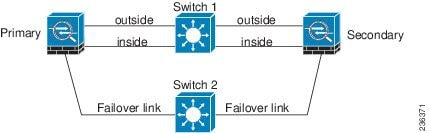
Figure 8-4 Connecting with a Cable

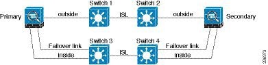
If the ASA data interfaces are connected to more than one set of switches, then a failover link can be connected to one of the switches, preferably the switch on the secure (inside) side of network, as shown in Figure 8-5.
Figure 8-5 Connecting with a Secure Switch
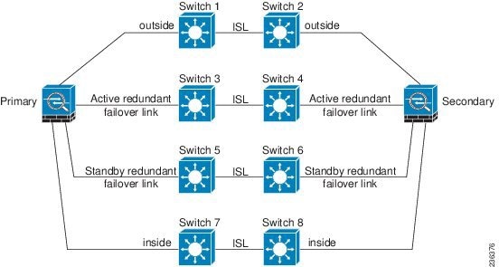
The most reliable failover configurations use a redundant interface on the failover link, as shown in Figure 8-6 and Figure 8-7.
Figure 8-6 Connecting with Redundant Interfaces
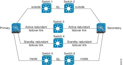
Figure 8-7 Connecting with Inter-switch Links
MAC Addresses and IP Addresses
When you configure your interfaces, you must specify an active IP address and a standby IP address on the same network.
1.![]() When the primary unit or failover group fails over, the secondary unit assumes the IP addresses and MAC addresses of the primary unit and begins passing traffic.
When the primary unit or failover group fails over, the secondary unit assumes the IP addresses and MAC addresses of the primary unit and begins passing traffic.
2.![]() The unit that is now in standby state takes over the standby IP addresses and MAC addresses.
The unit that is now in standby state takes over the standby IP addresses and MAC addresses.
Because network devices see no change in the MAC to IP address pairing, no ARP entries change or time out anywhere on the network.
Note![]() If the secondary unit boots without detecting the primary unit, the secondary unit becomes the active unit and uses its own MAC addresses, because it does not know the primary unit MAC addresses. However, when the primary unit becomes available, the secondary (active) unit changes the MAC addresses to those of the primary unit, which can cause an interruption in your network traffic.Similarly, if you swap out the primary unit with new hardware, a new MAC address is used.
If the secondary unit boots without detecting the primary unit, the secondary unit becomes the active unit and uses its own MAC addresses, because it does not know the primary unit MAC addresses. However, when the primary unit becomes available, the secondary (active) unit changes the MAC addresses to those of the primary unit, which can cause an interruption in your network traffic.Similarly, if you swap out the primary unit with new hardware, a new MAC address is used.
Virtual MAC addresses guard against this disruption because the active MAC addresses are known to the secondary unit at startup, and remain the same in the case of new primary unit hardware. In multiple context mode, the ASA generates virtual active and standby MAC addresses by default. See Information About MAC Addresses for more information. In single context mode, you can manually configure virtual MAC addresses; see Configuring Active/Active Failover for more information.
If you do not configure virtual MAC addresses, you might need to clear the ARP tables on connected routers to restore traffic flow. The ASA does not send gratuitous ARPs for static NAT addresses when the MAC address changes, so connected routers do not learn of the MAC address change for these addresses.
Note![]() The IP address and MAC address for the state link do not change at failover; the only exception is if the state link is configured on a regular data interface.
The IP address and MAC address for the state link do not change at failover; the only exception is if the state link is configured on a regular data interface.
Intra- and Inter-Chassis Module Placement for the ASA Services Module
You can place the primary and secondary ASASMs within the same switch or in two separate switches. The following sections describe each option:
Intra-Chassis Failover
If you install the secondary ASASM in the same switch as the primary ASASM, you protect against module-level failure. To protect against switch-level failure, as well as module-level failure, see Inter-Chassis Failover.
Even though both ASASMs are assigned the same VLANs, only the active module takes part in networking. The standby module does not pass any traffic.
Figure 8-8 shows a typical intra-switch configuration.
Figure 8-8 Intra-Switch Failover

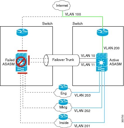
Inter-Chassis Failover
To protect against switch-level failure, you can install the secondary ASASM in a separate switch. The ASASM does not coordinate failover directly with the switch, but it works harmoniously with the switch failover operation. See the switch documentation to configure failover for the switch.
For the best reliability of failover communications between ASASMs, we recommend that you configure an EtherChannel trunk port between the two switches to carry the failover and state VLANs.
For other VLANs, you must ensure that both switches have access to all firewall VLANs, and that monitored VLANs can successfully pass hello packets between both switches.
Figure 8-9 shows a typical switch and ASASM redundancy configuration. The trunk between the two switches carries the failover ASASM VLANs (VLANs 10 and 11).
Note![]() ASASM failover is independent of the switch failover operation; however, ASASM works in any switch failover scenario.
ASASM failover is independent of the switch failover operation; however, ASASM works in any switch failover scenario.

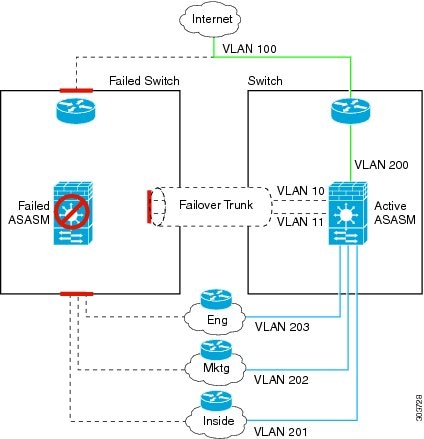
If the primary ASASM fails, then the secondary ASASM becomes active and successfully passes the firewall VLANs (Figure 8-10).
If the entire switch fails, as well as the ASASM (such as in a power failure), then both the switch and the ASASM fail over to their secondary units (Figure 8-11).
Stateless and Stateful Failover
The ASA supports two types of failover, stateless and stateful for both the Active/Standby and Active/Active modes.
Note![]() Some configuration elements for clientless SSL VPN (such as bookmarks and customization) use the VPN failover subsystem, which is part of Stateful Failover. You must use Stateful Failover to synchronize these elements between the members of the failover pair. Stateless failover is not recommended for clientless SSL VPN.
Some configuration elements for clientless SSL VPN (such as bookmarks and customization) use the VPN failover subsystem, which is part of Stateful Failover. You must use Stateful Failover to synchronize these elements between the members of the failover pair. Stateless failover is not recommended for clientless SSL VPN.
Stateless Failover
When a failover occurs, all active connections are dropped. Clients need to reestablish connections when the new active unit takes over.
Note![]() Some configuration elements for clientless SSL VPN (such as bookmarks and customization) use the VPN failover subsystem, which is part of Stateful Failover. You must use Stateful Failover to synchronize these elements between the members of the failover pair. Stateless (regular) failover is not recommended for clientless SSL VPN.
Some configuration elements for clientless SSL VPN (such as bookmarks and customization) use the VPN failover subsystem, which is part of Stateful Failover. You must use Stateful Failover to synchronize these elements between the members of the failover pair. Stateless (regular) failover is not recommended for clientless SSL VPN.
Stateful Failover
When Stateful Failover is enabled, the active unit continually passes per-connection state information to the standby unit, or in Active/Active failover, between the active and standby failover groups. After a failover occurs, the same connection information is available at the new active unit. Supported end-user applications are not required to reconnect to keep the same communication session.
Supported Features
The following state information is passed to the standby ASA when Stateful Failover is enabled:
- NAT translation table
- TCP connection states
- UDP connection states
- The ARP table
- The Layer 2 bridge table (when running in transparent firewall mode)
- The HTTP connection states (if HTTP replication is enabled)—By default, the ASA does not replicate HTTP session information when Stateful Failover is enabled. Because HTTP sessions are typically short-lived, and because HTTP clients typically retry failed connection attempts, not replicating HTTP sessions increases system performance without causing serious data or connection loss.
- The ISAKMP and IPsec SA table
- GTP PDP connection database
- SIP signalling sessions
- ICMP connection state—ICMP connection replication is enabled only if the respective interface is assigned to an asymmetric routing group.
- Dynamic Routing Protocols—Stateful Failover participates in dynamic routing protocols, like OSPF and EIGRP, so routes that are learned through dynamic routing protocols on the active unit are maintained in a Routing Information Base (RIB) table on the standby unit. Upon a failover event, packets travel normally with minimal disruption to traffic because the active secondary ASA initially has rules that mirror the primary ASA. Immediately after failover, the re-convergence timer starts on the newly Active unit. Then the epoch number for the RIB table increments. During re-convergence, OSPF and EIGRP routes become updated with a new epoch number. Once the timer is expired, stale route entries (determined by the epoch number) are removed from the table. The RIB then contains the newest routing protocol forwarding information on the newly Active unit.
Note![]() Routes are synchronized only for link-up or link-down events on an active unit. If the link goes up or down on the standby unit, dynamic routes sent from the active unit may be lost. This is normal, expected behavior
Routes are synchronized only for link-up or link-down events on an active unit. If the link goes up or down on the standby unit, dynamic routes sent from the active unit may be lost. This is normal, expected behavior
- Cisco IP SoftPhone sessions—If a failover occurs during an active Cisco IP SoftPhone session, the call remains active because the call session state information is replicated to the standby unit. When the call is terminated, the IP SoftPhone client loses connection with the Cisco Call Manager. This connection loss occurs because there is no session information for the CTIQBE hangup message on the standby unit. When the IP SoftPhone client does not receive a response back from the Call Manager within a certain time period, it considers the Call Manager unreachable and unregisters itself.
- VPN—VPN end-users do not have to reauthenticate or reconnect the VPN session after a failover. However, applications operating over the VPN connection could lose packets during the failover process and not recover from the packet loss.
Unsupported Features
The following state information is not passed to the standby ASA when Stateful Failover is enabled:
- The HTTP connection table (unless HTTP replication is enabled)
- The user authentication (uauth) table
- Application inspections that are subject to advanced TCP-state tracking—The TCP state of these connections is not automatically replicated. While these connections are replicated to the standby unit, there is a best-effort attempt to re-establish a TCP state.
- DHCP server address leases
- State information for modules, such as the ASA IPS SSP or ASA CX SSP.
- Phone proxy connections—When the active unit goes down, the call fails, media stops flowing, and the phone should unregister from the failed unit and reregister with the active unit. The call must be re-established.
- Selected clientless SSL VPN features:
–![]() IPv6 clientless or Anyconnect sessions
IPv6 clientless or Anyconnect sessions
–![]() Citrix authentication (Citrix users must reauthenticate after failover)
Citrix authentication (Citrix users must reauthenticate after failover)
Transparent Firewall Mode Requirements
Transparent Mode Requirements for Appliances
When the active unit fails over to the standby unit, the connected switch port running Spanning Tree Protocol (STP) can go into a blocking state for 30 to 50 seconds when it senses the topology change. To avoid traffic loss while the port is in a blocking state, you can configure one of the following workarounds depending on the switch port mode:
The PortFast feature immediately transitions the port into STP forwarding mode upon linkup. The port still participates in STP. So if the port is to be a part of the loop, the port eventually transitions into STP blocking mode.
- Trunk mode—Block BPDUs on the ASA on both the inside and outside interfaces with an EtherType access rule.
Blocking BPDUs disables STP on the switch. Be sure not to have any loops involving the ASA in your network layout.
If neither of the above options are possible, then you can use one of the following less desirable workarounds that impacts failover functionality or STP stability:
Transparent Mode Requirements for Modules
To avoid loops when you use failover in transparent mode, you should allow BPDUs to pass (the default), and you must use switch software that supports BPDU forwarding.
Loops can occur if both modules are active at the same time, such as when both modules are discovering each other’s presence, or due to a bad failover link. Because the ASASMs bridge packets between the same two VLANs, loops can occur when inside packets destined for the outside get endlessly replicated by both ASASMs (see Figure 8-12). The spanning tree protocol can break such loops if there is a timely exchange of BPDUs. To break the loop, BPDUs sent between VLAN 200 and VLAN 201 need to be bridged.
Figure 8-12 Transparent Mode Loop

Failover Health Monitoring
The ASA monitors each unit for overall health and for interface health. This section includes information about how the ASA performs tests to determine the state of each unit.
Unit Health Monitoring
The ASA determines the health of the other unit by monitoring the failover link. When a unit does not receive three consecutive hello messages on the failover link, the unit sends interface hello messages on each data interface, including the failover link, to validate whether or not the peer is responsive. The action that the ASA takes depends on the response from the other unit. See the following possible actions:
- If the ASA receives a response on the failover link, then it does not fail over.
- If the ASA does not receive a response on the failover link, but it does receive a response on a data interface, then the unit does not failover. The failover link is marked as failed. You should restore the failover link as soon as possible because the unit cannot fail over to the standby while the failover link is down.
- If the ASA does not receive a response on any interface, then the standby unit switches to active mode and classifies the other unit as failed.
Interface Monitoring
You can monitor up to 250 interfaces (in multiple mode, divided between all contexts). You should monitor important interfaces. For example in multiple mode, you might configure one context to monitor a shared interface. (Because the interface is shared, all contexts benefit from the monitoring.)
When a unit does not receive hello messages on a monitored interface for half of the configured hold time, it runs the following tests:
1.![]() Link Up/Down test—A test of the interface status. If the Link Up/Down test indicates that the interface is operational, then the ASA performs network tests. The purpose of these tests is to generate network traffic to determine which (if either) unit has failed. At the start of each test, each unit clears its received packet count for its interfaces. At the conclusion of each test, each unit looks to see if it has received any traffic. If it has, the interface is considered operational. If one unit receives traffic for a test and the other unit does not, the unit that received no traffic is considered failed. If neither unit has received traffic, then the next test is used.
Link Up/Down test—A test of the interface status. If the Link Up/Down test indicates that the interface is operational, then the ASA performs network tests. The purpose of these tests is to generate network traffic to determine which (if either) unit has failed. At the start of each test, each unit clears its received packet count for its interfaces. At the conclusion of each test, each unit looks to see if it has received any traffic. If it has, the interface is considered operational. If one unit receives traffic for a test and the other unit does not, the unit that received no traffic is considered failed. If neither unit has received traffic, then the next test is used.
2.![]() Network Activity test—A received network activity test. The unit counts all received packets for up to 5 seconds. If any packets are received at any time during this interval, the interface is considered operational and testing stops. If no traffic is received, the ARP test begins.
Network Activity test—A received network activity test. The unit counts all received packets for up to 5 seconds. If any packets are received at any time during this interval, the interface is considered operational and testing stops. If no traffic is received, the ARP test begins.
3.![]() ARP test—A reading of the unit ARP cache for the 2 most recently acquired entries. One at a time, the unit sends ARP requests to these machines, attempting to stimulate network traffic. After each request, the unit counts all received traffic for up to 5 seconds. If traffic is received, the interface is considered operational. If no traffic is received, an ARP request is sent to the next machine. If at the end of the list no traffic has been received, the ping test begins.
ARP test—A reading of the unit ARP cache for the 2 most recently acquired entries. One at a time, the unit sends ARP requests to these machines, attempting to stimulate network traffic. After each request, the unit counts all received traffic for up to 5 seconds. If traffic is received, the interface is considered operational. If no traffic is received, an ARP request is sent to the next machine. If at the end of the list no traffic has been received, the ping test begins.
4.![]() Broadcast Ping test—A ping test that consists of sending out a broadcast ping request. The unit then counts all received packets for up to 5 seconds. If any packets are received at any time during this interval, the interface is considered operational and testing stops.
Broadcast Ping test—A ping test that consists of sending out a broadcast ping request. The unit then counts all received packets for up to 5 seconds. If any packets are received at any time during this interval, the interface is considered operational and testing stops.
Monitored interfaces can have the following status:
- Unknown—Initial status. This status can also mean the status cannot be determined.
- Normal—The interface is receiving traffic.
- Testing—Hello messages are not heard on the interface for five poll times.
- Link Down—The interface or VLAN is administratively down.
- No Link—The physical link for the interface is down.
- Failed—No traffic is received on the interface, yet traffic is heard on the peer interface.
If an interface has IPv4 and IPv6 addresses configured on it, the ASA uses the IPv4 addresses to perform the health monitoring.
If an interface has only IPv6 addresses configured on it, then the ASA uses IPv6 neighbor discovery instead of ARP to perform the health monitoring tests. For the broadcast ping test, the ASA uses the IPv6 all nodes address (FE02::1).
If all network tests fail for an interface, but this interface on the other unit continues to successfully pass traffic, then the interface is considered to be failed. If the threshold for failed interfaces is met, then a failover occurs. If the other unit interface also fails all the network tests, then both interfaces go into the “Unknown” state and do not count towards the failover limit.
An interface becomes operational again if it receives any traffic. A failed ASA returns to standby mode if the interface failure threshold is no longer met.
Note![]() If a failed unit does not recover and you believe it should not be failed, you can reset the state by entering the failover reset command. If the failover condition persists, however, the unit will fail again.
If a failed unit does not recover and you believe it should not be failed, you can reset the state by entering the failover reset command. If the failover condition persists, however, the unit will fail again.
Failover Times
Table 8-1 shows the minimum, default, and maximum failover times.
|
|
|
|
|
|---|---|---|---|
Active unit interface up, but connection problem causes interface testing. |
Configuration Synchronization
Failover includes two types of configuration synchronization:
Running Configuration Replication
Running configuration replication occurs when one or both devices in the failover pair boot. Configurations are always synchronized from the active unit to the standby unit. When the standby unit completes its initial startup, it clears its running configuration (except for the failover commands needed to communicate with the active unit), and the active unit sends its entire configuration to the standby unit.
When the replication starts, the ASA console on the active unit displays the message “Beginning configuration replication: Sending to mate,” and when it is complete, the ASA displays the message “End Configuration Replication to mate.” Depending on the size of the configuration, replication can take from a few seconds to several minutes.
On the standby unit, the configuration exists only in running memory. You should save the configuration to flash memory.
Note![]() During replication, commands entered on the active unit may not replicate properly to the standby unit, and commands entered on the standby unit may be overwritten by the configuration being replicated from the active unit. Avoid entering commands on either unit during the configuration replication process.
During replication, commands entered on the active unit may not replicate properly to the standby unit, and commands entered on the standby unit may be overwritten by the configuration being replicated from the active unit. Avoid entering commands on either unit during the configuration replication process.
Note![]() The crypto ca server command and related sub commands are not synchronized to the failover peer.
The crypto ca server command and related sub commands are not synchronized to the failover peer.
Note Configuration syncing does not replicate the following files and configuration components, so you must copy these files manually so they match:
- AnyConnect images
- CSD images
- AnyConnect profiles
- Local Certificate Authorities (CAs)
- ASA images
- ASDM images
Command Replication
After startup, commands that you enter on the active unit are immediately replicated to the standby unit.You do not have to save the active configuration to flash memory to replicate the commands.
In Active/Active failover,changes entered in the system execution space are replicated from the unit on which failover group 1 is in the active state.
Failure to enter the changes on the appropriate unit for command replication to occur causes the configurations to be out of synchronization. Those changes may be lost the next time the initial configuration synchronization occurs.
The following commands are replicated to the standby ASA:
- All configuration commands except for mode, firewall, and failover lan unit
- copy running-config startup-config
- delete
- mkdir
- rename
- rmdir
- write memory
The following commands are not replicated to the standby ASA:
Information About Active/Standby Failover
Active/Standby failover lets you use a standby ASA to take over the functionality of a failed unit. When the active unit fails, it changes to the standby state while the standby unit changes to the active state.
Note![]() For multiple context mode, the ASA can fail over the entire unit (including all contexts) but cannot fail over individual contexts separately.
For multiple context mode, the ASA can fail over the entire unit (including all contexts) but cannot fail over individual contexts separately.
Primary/Secondary Roles and Active/Standby Status
The main differences between the two units in a failover pair are related to which unit is active and which unit is standby, namely which IP addresses to use and which unit actively passes traffic.
However, a few differences exist between the units based on which unit is primary (as specified in the configuration) and which unit is secondary:
- The primary unit always becomes the active unit if both units start up at the same time (and are of equal operational health).
- The primary unit MAC addresses are always coupled with the active IP addresses. The exception to this rule occurs when the secondary unit is active and cannot obtain the primary unit MAC addresses over the failover link. In this case, the secondary unit MAC addresses are used.
Active Unit Determination at Startup
Failover Events
In Active/Standby failover, failover occurs on a unit basis. Even on systems running in multiple context mode, you cannot fail over individual or groups of contexts.
Table 8-2 shows the failover action for each failure event. For each failure event, the table shows the failover policy (failover or no failover), the action taken by the active unit, the action taken by the standby unit, and any special notes about the failover condition and actions.
Information About Active/Active Failover
This section describes Active/Active failover. This section includes the following topics:
Active/Active Failover Overview
In an Active/Active failover configuration, both ASAs can pass network traffic. Active/Active failover is only available to ASAs in multiple context mode. In Active/Active failover, you divide the security contexts on the ASA into a maximum of 2 failover groups.
A failover group is simply a logical group of one or more security contexts. You can assign failover group to be active on the primary ASA, and failover group 2 to be active on the secondary ASA. When a failover occurs, it occurs at the failover group level. For example, depending on interface failure patterns, it is possible for failover group 1 to fail over to the secondary ASA, and subsequently failover group 2 to fail over to the primary ASA. This event could occur if the interfaces in failover group 1 are down on the primary ASA but up on the secondary ASA, while the interfaces in failover group 2 are down on the secondary ASA but up on the primary ASA.
The admin context is always a member of failover group 1. Any unassigned security contexts are also members of failover group 1 by default. If you want Active/Active failover, but are otherwise uninterested in multiple contexts, the simplest configuration would be to add one additional context and assign it to failover group 2.
Note![]() When configuring Active/Active failover, make sure that the combined traffic for both units is within the capacity of each unit.
When configuring Active/Active failover, make sure that the combined traffic for both units is within the capacity of each unit.
Note![]() You can assign both failover groups to one ASA if desired, but then you are not taking advantage of having two active ASAs.
You can assign both failover groups to one ASA if desired, but then you are not taking advantage of having two active ASAs.
Primary/Secondary Roles and Active/Standby Status for a Failover Group
As in Active/Standby failover, one unit in an Active/Active failover pair is designated the primary unit, and the other unit the secondary unit. Unlike Active/Standby failover, this designation does not indicate which unit becomes active when both units start simultaneously. Instead, the primary/secondary designation does two things:
Active Unit Determination for Failover Groups at Startup
The unit on which a failover group becomes active is determined as follows:
- When a unit boots while the peer unit is not available, both failover groups become active on the unit.
- When a unit boots while the peer unit is active (with both failover groups in the active state), the failover groups remain in the active state on the active unit regardless of the primary or secondary preference of the failover group until one of the following occurs:
–![]() You manually force a failover.
You manually force a failover.
–![]() You configured preemption for the failover group, which causes the failover group to automatically become active on the preferred unit when the unit becomes available.
You configured preemption for the failover group, which causes the failover group to automatically become active on the preferred unit when the unit becomes available.
Failover Events
In an Active/Active failover configuration, failover occurs on a failover group basis, not a system basis. For example, if you designate both failover groups as active on the primary unit, and failover group 1 fails, then failover group 2 remains active on the primary unit while failover group 1 becomes active on the secondary unit.
Because a failover group can contain multiple contexts, and each context can contain multiple interfaces, it is possible for all interfaces in a single context to fail without causing the associated failover group to fail.
Table 8-3 shows the failover action for each failure event. For each failure event, the policy (whether or not failover occurs), actions for the active failover group, and actions for the standby failover group are given.
Licensing Requirements Failover
Failover units do not require the same license on each unit. If you have licenses on both units, they combine into a single running failover cluster license. There are some exceptions to this rule. See the following table for precise licensing requirements for failover.
Prerequisites for Failover
Guidelines and Limitations
For Auto Update guidelines with failover, see Auto Update Server Support in Failover Configurations.
- Active/Standby mode is supported in single and multiple context mode.
- Active/Active mode is supported only in multiple context mode.
- For multiple context mode, perform all steps in the system execution space unless otherwise noted.
- ASA failover replication fails if you try to make a configuration change in two or more contexts at the same time. The workaround is to make configuration changes in each context sequentially.
Supported in transparent and routed firewall mode.
Stateful failover is not supported on the ASA 5505. See Licensing Requirements Failover for other guidelines.
Additional Guidelines and Limitations
- Configuring port security on the switch(es) connected to an ASA failover pair can cause communication problems when a failover event occurs. This problem occurs when a secure MAC address configured or learned on one secure port moves to another secure port, a violation is flagged by the switch port security feature.
- You can monitor up to 250 interfaces on a unit, across all contexts.
- For Active/Active failover, no two interfaces in the same context should be configured in the same ASR group.
- For Active/Active failover, you can define a maximum of two failover groups.
- For Active/Active failover, when removing failover groups, you must remove failover group 1 last. Failover group1 always contains the admin context. Any context not assigned to a failover group defaults to failover group 1. You cannot remove a failover group that has contexts explicitly assigned to it.
Default Settings
By default, the failover policy consists of the following:
- No HTTP replication in Stateful Failover.
- A single interface failure causes failover.
- The interface poll time is 5 seconds.
- The interface hold time is 25 seconds.
- The unit poll time is 1 second.
- The unit hold time is 15 seconds.
- Virtual MAC addresses are enabled in multiple context mode; in single context mode, they are disabled.
- Monitoring on all physical interfaces, or for the ASA 5505 and ASASM, all VLAN interfaces.
Configuring Active/Standby Failover
The High Availability and Scalability Wizard guides you through a step-by-step process of creating an Active/Standby failover configuration.
- Detailed Steps 1—Starting the Wizard
- Detailed Steps 2—Failover Peer Connectivity and Compatibility Check
- Detailed Steps 3—LAN Link Configuration
- Detailed Steps 4—State Link Configuration
- Detailed Steps 5—Standby Address Configuration
- Detailed Steps 6—Summary
Detailed Steps 1—Starting the Wizard
Step 1![]() Choose Wizards > High Availability and Scalability.
Choose Wizards > High Availability and Scalability.
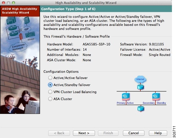
Step 2![]() In the Configuration Type screen, click Configure Active/Standby failover, and click Next.
In the Configuration Type screen, click Configure Active/Standby failover, and click Next.
The Failover Peer Connectivity and Compatibility screen appears. See Detailed Steps 2—Failover Peer Connectivity and Compatibility Check.
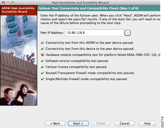
Detailed Steps 2—Failover Peer Connectivity and Compatibility Check
Step 1![]() In the Peer IP Address field, enter the IP address of the peer unit. This address must be an interface that has ASDM access enabled on it.
In the Peer IP Address field, enter the IP address of the peer unit. This address must be an interface that has ASDM access enabled on it.
By default, the peer address is assigned to be the standby address for the ASDM management interface.
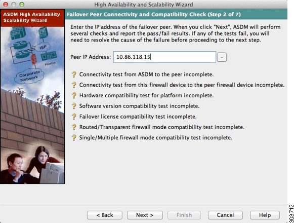
Step 2![]() Click Next to perform connectivity and compatibility tests. You are prompted to log into the peer unit.
Click Next to perform connectivity and compatibility tests. You are prompted to log into the peer unit.
If the tests succeed, the LAN Link Configuration screen appears. See Detailed Steps 3—LAN Link Configuration.
If any of the tests fail, you see an error dialog box.
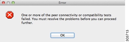
After you click OK, you are returned to the compatibility check screen, which shows which tests failed. Click Cancel to exit the wizard and resolve any issues before trying again.
Detailed Steps 3—LAN Link Configuration
Step 1![]() Configure the failover link parameters:
Configure the failover link parameters:
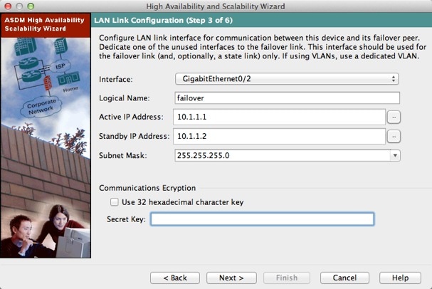
a.![]() Interface—Choose the interface to use for failover communication.
Interface—Choose the interface to use for failover communication.
b.![]() Logical Name—Enter a name for the interface.
Logical Name—Enter a name for the interface.
c.![]() Active IP Address—Enter the IP address used for the failover link on the primary unit. This should be on an unused subnet.
Active IP Address—Enter the IP address used for the failover link on the primary unit. This should be on an unused subnet.
d.![]() Standby IP Address—Enter the IP address used for the failover link on the secondary unit, on the same network as the active IP address.
Standby IP Address—Enter the IP address used for the failover link on the secondary unit, on the same network as the active IP address.
e.![]() Subnet Mask—Enter or choose a subnet mask for the Active IP and Standby IP addresses.
Subnet Mask—Enter or choose a subnet mask for the Active IP and Standby IP addresses.
f.![]() (ASA 5505 only) Switch Port—Choose the switch port from the drop-down list, which includes the current VLAN assigned to each switch port and any name associated with the VLAN. By default, VLAN 1 is the inside interface, so you should choose a different VLAN.
(ASA 5505 only) Switch Port—Choose the switch port from the drop-down list, which includes the current VLAN assigned to each switch port and any name associated with the VLAN. By default, VLAN 1 is the inside interface, so you should choose a different VLAN.
Note![]() To provide sufficient bandwidth for failover, do not use trunks or PoE for failover.
To provide sufficient bandwidth for failover, do not use trunks or PoE for failover.
g.![]() (Optional) Communications Encryption—Encrypt communications on the failover link. Note : Instead of a Secret Key, we recommend using an IPsec preshared key, which you can configure after you exit the wizard (see Modifying the Failover Setup).
(Optional) Communications Encryption—Encrypt communications on the failover link. Note : Instead of a Secret Key, we recommend using an IPsec preshared key, which you can configure after you exit the wizard (see Modifying the Failover Setup).
–![]() Secret Key—Enter the secret key used to encrypt failover communication. If you leave this field blank, failover communication, including any passwords or keys in the configuration that are sent during command replication, will be in clear text.
Secret Key—Enter the secret key used to encrypt failover communication. If you leave this field blank, failover communication, including any passwords or keys in the configuration that are sent during command replication, will be in clear text.
Use 32 hexadecimal character key—To use a 32-hexadecimal key for the secret key, check this check box.
The State Link Configuration screen appears. See Detailed Steps 4—State Link Configuration.
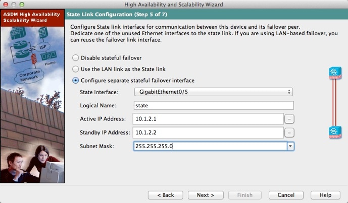
Detailed Steps 4—State Link Configuration
Step 1![]() Choose one of the following options for the state link:
Choose one of the following options for the state link:
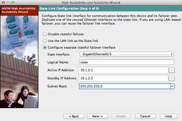
Step 2![]() If you choose another interface for Stateful Failover, configure the following parameters:
If you choose another interface for Stateful Failover, configure the following parameters:
a.![]() State interface—Choose an unused interface.
State interface—Choose an unused interface.
b.![]() Logical Name—Enter the name for the state link.
Logical Name—Enter the name for the state link.
c.![]() Active IP Address—Enter the IP address for the state link on the primary unit. This should be on an unused subnet, different from the failover link.
Active IP Address—Enter the IP address for the state link on the primary unit. This should be on an unused subnet, different from the failover link.
d.![]() Standby IP Address—Enter the IP address for the state link on the secondary unit, on the same network as the active IP address.
Standby IP Address—Enter the IP address for the state link on the secondary unit, on the same network as the active IP address.
e.![]() Subnet Mask—Enter or choose a subnet mask for the Active IP and Standby IP addresses.
Subnet Mask—Enter or choose a subnet mask for the Active IP and Standby IP addresses.
The Standby Address Configuration screen appears. See Detailed Steps 5—Standby Address Configuration.
Detailed Steps 5—Standby Address Configuration
Step 1![]() Assign standby IP addresses to the data interfaces on the ASA. Any currently configured interfaces appear.
Assign standby IP addresses to the data interfaces on the ASA. Any currently configured interfaces appear.
By default, the peer address that you specified on the Failover Peer Connectivity and Compatibility screen is assigned to be the standby address for the ASDM management interface.
If you configure data interfaces later, you can assign standby IP addresses at that time, or on the Configuration > Device Management > High Availability > Failover > Interfaces tab (see Configuring Interface Monitoring and Standby Addresses).
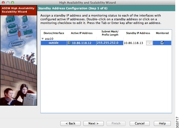
a.![]() Select the Active IP Address field to edit or add an active IP address.
Select the Active IP Address field to edit or add an active IP address.
b.![]() Select the Standby IP Address field to edit or add a standby IP address.
Select the Standby IP Address field to edit or add a standby IP address.
c.![]() Select the Subnet Mask/Prefix Length field to edit the subnet mask or prefix length.
Select the Subnet Mask/Prefix Length field to edit the subnet mask or prefix length.
d.![]() Check the Monitored check box to enable health monitoring for that interface. Uncheck the check box to disable health monitoring. By default, health monitoring of physical interfaces is enabled, and health monitoring of subinterfaces is disabled.
Check the Monitored check box to enable health monitoring for that interface. Uncheck the check box to disable health monitoring. By default, health monitoring of physical interfaces is enabled, and health monitoring of subinterfaces is disabled.
The Summary screen appears. See Detailed Steps 6—Summary.
Detailed Steps 6—Summary
Step 1![]() Verify your settings and click Finish to send your configuration to the primary unit.
Verify your settings and click Finish to send your configuration to the primary unit.
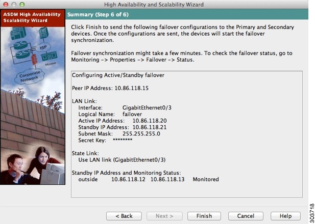
The wizard shows the Waiting for Config Sync screen.
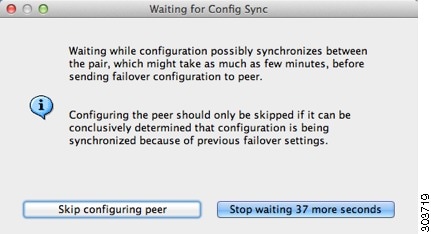
After the specified time period is over, the wizard sends the failover configuration to the secondary unit, and you see an information screen showing that failover configuration is complete.
- If you do not know if failover is already enabled on the secondary unit, then wait for the specified period.
- If you know failover is already enabled, click Skip configuring peer.
- If you know the secondary unit is not yet failover-enabled, click Stop waiting xx more seconds, and the failover bootstrap configuration is sent to the secondary unit immediately.
Configuring Active/Active Failover
The High Availability and Scalability Wizard guides you through a step-by-step process of creating an Active/Active failover configuration.
- Detailed Steps 1—Starting the Wizard
- Detailed Steps 2—Failover Peer Connectivity and Compatibility Check
- Detailed Steps 3—Security Context Configuration
- Detailed Steps 4—LAN Link Configuration
- Detailed Steps 5—State Link Configuration
- Detailed Steps 6—Standby Address Configuration
- Detailed Steps 7—Summary
Detailed Steps 1—Starting the Wizard
Step 1![]() Choose Wizards > High Availability and Scalability.
Choose Wizards > High Availability and Scalability.

Step 2![]() In the Configuration Type screen, click Configure Active/Active failover, and click Next.
In the Configuration Type screen, click Configure Active/Active failover, and click Next.
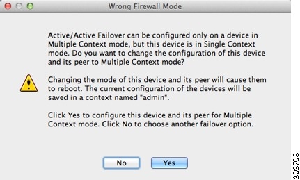
- If your devices are already in multiple context mode, the Failover Peer Connectivity and Compatibility screen appears.
- If your devices are not yet in multiple context mode, you see the Wrong Firewall Mode dialog box. Click Yes to change the mode as part of the wizard, or click No to exit the wizard. If you click Yes, you are returned to the Configuration Type screen. Click Next. the Failover Peer Connectivity and Compatibility screen appears. For more information about multiple context mode, see Chapter9, “Multiple Context Mode”
See Detailed Steps 2—Failover Peer Connectivity and Compatibility Check.
Detailed Steps 2—Failover Peer Connectivity and Compatibility Check
Step 1![]() In the Peer IP Address field, enter the IP address of the peer unit. This address must be an interface that has ASDM access enabled on it.
In the Peer IP Address field, enter the IP address of the peer unit. This address must be an interface that has ASDM access enabled on it.
By default, the peer address is assigned to be the standby address for the interface to which ASDM is connected.
Step 2![]() Click Next to perform the following connectivity and compatibility tests:
Click Next to perform the following connectivity and compatibility tests:
- Connectivity test from this ASDM to the peer unit
- Connectivity test from this firewall device to the peer firewall device
- Hardware compatibility test for the platform
- Software version compatibility
- Failover license compatibility
- Firewall mode compatibility (routed or transparent)
- Context mode compatibility (single or multiple)
Step 3![]() You are prompted to log into the peer unit.
You are prompted to log into the peer unit.
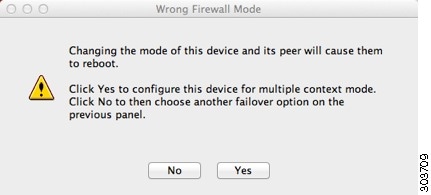
Click Yes to change the mode and reload both units. You see the Status dialog box showing a countdown while ASDM waits for the units to reload.
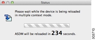
At the end of the countdown, ASDM reconnects to the primary unit and you return to the Failover Peer Connectivity and Compatibility screen. Click Next to recheck compatibility.
- If the tests succeed, the Security Context Configuration screen appears. See Detailed Steps 3—Security Context Configuration.
- If any of the tests fail, you see an error dialog box.
After you click OK, you are returned to the compatibility check screen, which shows which tests failed. Click Cancel to exit the wizard and resolve any issues before trying again.
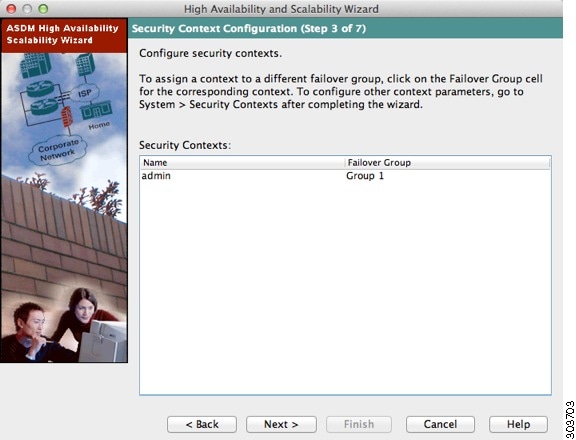
Detailed Steps 3—Security Context Configuration
Step 1![]() For existing contexts, you can set the failover group (1 or 2). If you converted to multiple context mode as part of the wizard, you will only see the admin context. You can add other contexts after you exit the wizard.
For existing contexts, you can set the failover group (1 or 2). If you converted to multiple context mode as part of the wizard, you will only see the admin context. You can add other contexts after you exit the wizard.
The LAN Link Configuration screen appears. See Detailed Steps 4—LAN Link Configuration.
Detailed Steps 4—LAN Link Configuration
Step 1![]() Configure the failover link parameters:
Configure the failover link parameters:
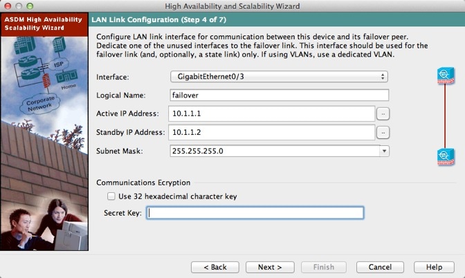
a.![]() Interface—Choose the interface to use for failover communication.
Interface—Choose the interface to use for failover communication.
b.![]() Logical Name—Enter a name for the interface.
Logical Name—Enter a name for the interface.
c.![]() Active IP Address—Enter the IP address used for the failover link on the primary unit. This IP address should be on an unused subnet.
Active IP Address—Enter the IP address used for the failover link on the primary unit. This IP address should be on an unused subnet.
d.![]() Standby IP Address—Enter the IP address used for the failover link on the secondary unit.
Standby IP Address—Enter the IP address used for the failover link on the secondary unit.
e.![]() Subnet Mask—Enter or choose a subnet mask for the Active IP and Standby IP addresses.
Subnet Mask—Enter or choose a subnet mask for the Active IP and Standby IP addresses.
f.![]() (Optional) Communications Encryption—Encrypt communications on the failover link. Note : Instead of a Secret Key, we recommend using an IPsec preshared key, which you can configure after you exit the wizard (see Modifying the Failover Setup).
(Optional) Communications Encryption—Encrypt communications on the failover link. Note : Instead of a Secret Key, we recommend using an IPsec preshared key, which you can configure after you exit the wizard (see Modifying the Failover Setup).
–![]() Secret Key—Enter the secret key used to encrypt failover communication. If you leave this field blank, failover communication, including any passwords or keys in the configuration that are sent during command replication, will be in clear text.
Secret Key—Enter the secret key used to encrypt failover communication. If you leave this field blank, failover communication, including any passwords or keys in the configuration that are sent during command replication, will be in clear text.
Use 32 hexadecimal character key—To use a 32-hexadecimal key for the secret key, check this check box.
The State Link Configuration screen appears. See Detailed Steps 5—State Link Configuration.
Detailed Steps 5—State Link Configuration
Step 1![]() Choose one of the following options for the state link:
Choose one of the following options for the state link:
Step 2![]() If you choose another interface for Stateful Failover, configure the following parameters:
If you choose another interface for Stateful Failover, configure the following parameters:
a.![]() State interface—Choose an unused interface.
State interface—Choose an unused interface.
b.![]() Logical Name—Enter the name for the state link. For example, change the name to “state.”
Logical Name—Enter the name for the state link. For example, change the name to “state.”
c.![]() Active IP Address—Enter the IP address for the state link on the primary unit. This should be on an unused subnet, different from the failover link.
Active IP Address—Enter the IP address for the state link on the primary unit. This should be on an unused subnet, different from the failover link.
d.![]() Standby IP Address—Enter the IP address for the state link on the secondary unit.
Standby IP Address—Enter the IP address for the state link on the secondary unit.
e.![]() Subnet Mask—Enter or choose a subnet mask for the Active IP and Standby IP addresses.
Subnet Mask—Enter or choose a subnet mask for the Active IP and Standby IP addresses.
The Standby Address Configuration screen appears. See Detailed Steps 6—Standby Address Configuration.
Detailed Steps 6—Standby Address Configuration
Step 1![]() Assign standby IP addresses to the interfaces on the ASA. The interfaces currently configured on the failover devices appear.
Assign standby IP addresses to the interfaces on the ASA. The interfaces currently configured on the failover devices appear.
By default, the peer address that you specified on the Failover Peer Connectivity and Compatibility screen is assigned to be the standby address for the interface to which ASDM is connected.
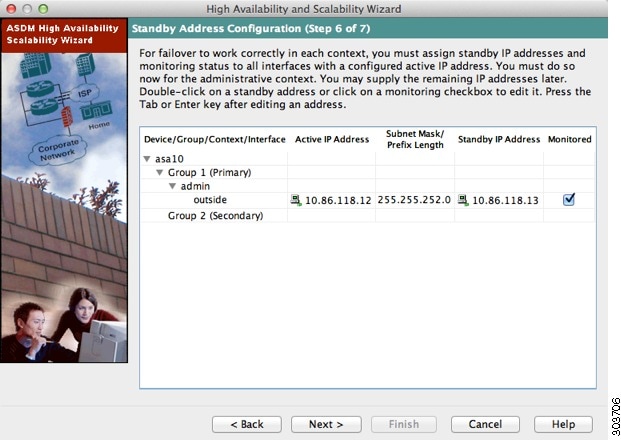
a.![]() Select the Active IP Address field to edit or add an active IP address. Changes to this field also appear in the Standby IP field for the corresponding interface on the failover peer unit.
Select the Active IP Address field to edit or add an active IP address. Changes to this field also appear in the Standby IP field for the corresponding interface on the failover peer unit.
b.![]() Select the Standby IP Address field to edit or add a standby IP address. Changes to this field also appear in the Active IP field for the corresponding interface on the failover peer unit.
Select the Standby IP Address field to edit or add a standby IP address. Changes to this field also appear in the Active IP field for the corresponding interface on the failover peer unit.
c.![]() Select the Subnet Mask/Prefix Length field to edit the subnet mask or prefix length.
Select the Subnet Mask/Prefix Length field to edit the subnet mask or prefix length.
d.![]() Check the Monitored check box to enable health monitoring for that interface. Uncheck the check box to disable health monitoring. By default, health monitoring of physical interfaces is enabled, and health monitoring of subinterfaces is disabled.
Check the Monitored check box to enable health monitoring for that interface. Uncheck the check box to disable health monitoring. By default, health monitoring of physical interfaces is enabled, and health monitoring of subinterfaces is disabled.
The Summary screen appears. See Detailed Steps 7—Summary.
Detailed Steps 7—Summary
Step 1![]() Verify your settings and click Finish to send your configuration to the primary device.
Verify your settings and click Finish to send your configuration to the primary device.
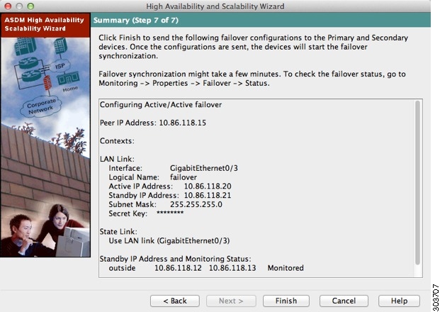
The wizard shows the Waiting for Config Sync screen. After the specified time period is over, the wizard sends the failover configuration to the secondary unit, and you see an information screen showing that failover configuration is complete.
- If you do not know if failover is already enabled on the secondary unit, then wait for the specified period.
- If you know failover is already enabled, click Skip configuring peer.
- If you know the secondary unit is not yet failover-enabled, click Stop waiting xx more seconds, and the failover bootstrap configuration is sent to the secondary unit immediately.
Configuring Optional Failover Parameters
You can customize failover settings as desired.
- Configuring Failover Criteria, HTTP Replication, Group Preemption, and MAC Addresses
- Configuring Interface Monitoring and Standby Addresses
- Configuring Support for Asymmetrically Routed Packets (Active/Active Mode)
Configuring Failover Criteria, HTTP Replication, Group Preemption, and MAC Addresses
See Default Settings for the default settings for many parameters that you can change in this section. For Active/Active mode, you set most criteria per failover group. This section includes enabling HTTP replication per failover group for Active/Active mode; to configure HTTP replication for Active/Standby mode, see Modifying the Failover Setup.
Prerequisites
Configure these settings in the system execution space in multiple context mode.
Detailed Steps
Step 1![]() Choose Config uration > Device Management > High Availability > Failover > Criteria.
Choose Config uration > Device Management > High Availability > Failover > Criteria.
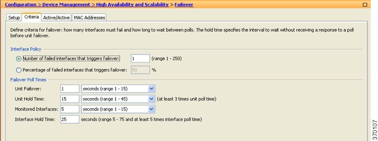
Step 2![]() In the Failover Poll Times area, configure the unit poll times:
In the Failover Poll Times area, configure the unit poll times:
- Unit Failover—The amount of time between hello messages among units. The range is between 1 and 15 seconds or between 200 and 999 milliseconds.
- Unit Hold Tim e —Sets the time during which a unit must receive a hello message on the failover link, or else the unit begins the testing process for peer failure. The range is between 1and 45 seconds or between 800 and 999 milliseconds. You cannot enter a value that is less than 3 times the polltime.
Note![]() Other settings on this pane apply only to Active/Standby mode. In Active/Active mode, you must configure the rest of the parameters per failover group.
Other settings on this pane apply only to Active/Standby mode. In Active/Active mode, you must configure the rest of the parameters per failover group.
Step 3![]() (Active/Active mode only) Choose Configuration > Device Management > High Availability > Failover > Active/Active, then choose a failover group and click Edit.
(Active/Active mode only) Choose Configuration > Device Management > High Availability > Failover > Active/Active, then choose a failover group and click Edit.


Step 4![]() (Active/Active mode only) To change the preferred role of the failover group, click either Primary or Secondary. If you used the wizard, failover group 1 is assigned to the primary unit, and failover group 2 is assigned to the secondary unit. If you want a non-standard configuration, you can specify different unit preferences if desired
(Active/Active mode only) To change the preferred role of the failover group, click either Primary or Secondary. If you used the wizard, failover group 1 is assigned to the primary unit, and failover group 2 is assigned to the secondary unit. If you want a non-standard configuration, you can specify different unit preferences if desired
Step 5![]() (Active/Active mode only) To configure failover group preemption, check the Preempt after booting with optional delay of check box.
(Active/Active mode only) To configure failover group preemption, check the Preempt after booting with optional delay of check box.
If one unit boots before the other, then both failover groups become active on that unit, despite the Primary or Secondary setting. This option causes the failover group to become active on the designated unit automatically when that unit becomes available.
You can enter an optional delay value, which specifies the number of seconds the failover group remains active on the current unit before automatically becoming active on the designated unit. Valid values are from 1 to 1200.
Note![]() If Stateful Failover is enabled, the preemption is delayed until the connections are replicated from the unit on which the failover group is currently active.
If Stateful Failover is enabled, the preemption is delayed until the connections are replicated from the unit on which the failover group is currently active.
Step 6![]() To configure the Interface Policy, choose one of the following:
To configure the Interface Policy, choose one of the following:
- Number of failed interfaces that triggers failover—Define a specific number of interfaces that must fail to trigger failover, from 1 to 250. When the number of failed monitored interfaces exceeds the value you specify, the ASA fails over.
- Percentage of failed interfaces that triggers failover—Define a percentage of configured interfaces that must fail to trigger failover. When the number of failed monitored interfaces exceeds the percentage you set, the ASA fails over.
Note![]() Do not use the “Use system failover interface policy” option. You can only set the policy per group at this time.
Do not use the “Use system failover interface policy” option. You can only set the policy per group at this time.
Step 7![]() For Active/Standby mode, configure interface poll times in the Failover Poll Time area.
For Active/Standby mode, configure interface poll times in the Failover Poll Time area.
For Active/Active mode, configure interface poll times on the Add/Edit Failover Group dialog box.
- Monitored Interfaces—The amount of time between polls among interfaces. The range is between 1and 15 seconds or 500 to 999 milliseconds.
- Interface Hold Time—Sets the time during which a data interface must receive a hello message on the data interface, after which the peer is declared failed. Valid values are from 5 to 75 seconds.
Step 8![]() (Active/Active mode only) To enable HTTP replication, check the Enable HTTP replication check box. For Active/Standby mode, see Modifying the Failover Setup. For both modes, see Modifying the Failover Setup section for the HTTP replication rate.
(Active/Active mode only) To enable HTTP replication, check the Enable HTTP replication check box. For Active/Standby mode, see Modifying the Failover Setup. For both modes, see Modifying the Failover Setup section for the HTTP replication rate.
Step 9![]() For Active/Standby mode, to configure virtual MAC addresses, click the MAC Addresses tab.
For Active/Standby mode, to configure virtual MAC addresses, click the MAC Addresses tab.
For Active/Active mode, go to the bottom of the Active/Active tab.
You can also set the MAC address using other methods, but we recommend using only one method. If you set the MAC address using multiple methods, the MAC address used depends on many variables, and might not be predictable.
Step 10![]() To add a new virtual MAC address entry, click Add.
To add a new virtual MAC address entry, click Add.
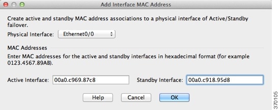
The Add/Edit Interface MAC Address dialog box appears.
Step 11![]() Choose and interface from the Physical Interface drop-down list.
Choose and interface from the Physical Interface drop-down list.
Step 12![]() In the Active MAC Address field, type the new MAC address for the active interface.
In the Active MAC Address field, type the new MAC address for the active interface.
Step 13![]() In the Standby MAC Address field, type the new MAC address for the standby interface.
In the Standby MAC Address field, type the new MAC address for the standby interface.
The interface is added to the table.
Step 15![]() (Active/Active mode only) Click OK.
(Active/Active mode only) Click OK.
Step 17![]() (Active/Active mode only) Repeat this procedure for the other failover group, if desired.
(Active/Active mode only) Repeat this procedure for the other failover group, if desired.
Configuring Interface Monitoring and Standby Addresses
By default, monitoring is enabled on all physical interfaces, or for the ASA 5505 and ASASM, all VLAN interfaces. You might want to exclude interfaces attached to less critical networks from affecting your failover policy.
If you did not configure the standby IP addresses in the wizard, you can configure them manually.
Guidelines
Detailed Steps
Step 1![]() In single mode, choose Configuration > Device Management > High Availability > Failover > Interfaces.
In single mode, choose Configuration > Device Management > High Availability > Failover > Interfaces.
In multiple context mode, within a context choose Configuration > Device Management > Failover > Interfaces

A list of configured interfaces appears. The Monitored column displays whether or not an interface is monitored as part of your failover criteria. If it is monitored, a check appears in the Monitored check box.
The IP address for each interface appears in the Active IP Address column. If configured, the standby IP address for the interface appears in the Standby IP address column. The failover link and state link do not display IP address; you cannot change those addresses from this tab.
Step 2![]() To disable monitoring of a listed interface, uncheck the Monitored check box for the interface.
To disable monitoring of a listed interface, uncheck the Monitored check box for the interface.
Step 3![]() To enable monitoring of a listed interface, check the Monitored check box for the interface.
To enable monitoring of a listed interface, check the Monitored check box for the interface.
Step 4![]() For each interface that does not have a standby IP address, double-click the Standby IP Address field and enter an IP address into the field.
For each interface that does not have a standby IP address, double-click the Standby IP Address field and enter an IP address into the field.
Configuring Support for Asymmetrically Routed Packets (Active/Active Mode)
When running in Active/Active failover, a unit may receive a return packet for a connection that originated through its peer unit. Because the ASA that receives the packet does not have any connection information for the packet, the packet is dropped. This drop most commonly occurs when the two ASAs in an Active/Active failover pair are connected to different service providers and the outbound connection does not use a NAT address.
You can prevent the return packets from being dropped by allowing asymmetrically routed packets. To do so, you assign the similar interfaces on each ASA to the same ASR group. For example, both ASAs connect to the inside network on the inside interface, but connect to separate ISPs on the outside interface. On the primary unit, assign the active context outside interface to ASR group 1; on the secondary unit, assign the active context outside interface to the same ASR group 1. When the primary unit outside interface receives a packet for which it has no session information, it checks the session information for the other interfaces in standby contexts that are in the same group; in this case, ASR group 1. If it does not find a match, the packet is dropped. If it finds a match, then one of the following actions occurs:
- If the incoming traffic originated on a peer unit, some or all of the layer 2 header is rewritten and the packet is redirected to the other unit. This redirection continues as long as the session is active.
- If the incoming traffic originated on a different interface on the same unit, some or all of the layer 2 header is rewritten and the packet is reinjected into the stream.
Note![]() This feature does not provide asymmetric routing; it restores asymmetrically routed packets to the correct interface.
This feature does not provide asymmetric routing; it restores asymmetrically routed packets to the correct interface.
Figure 8-13 shows an example of an asymmetrically routed packet.
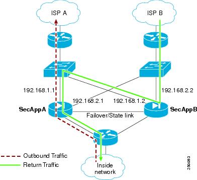
1.![]() An outbound session passes through the ASA with the active SecAppA context. It exits interface outsideISP-A (192.168.1.1).
An outbound session passes through the ASA with the active SecAppA context. It exits interface outsideISP-A (192.168.1.1).
2.![]() Because of asymmetric routing configured somewhere upstream, the return traffic comes back through the interface outsideISP-B (192.168.2.2) on the ASAwith the active SecAppB context.
Because of asymmetric routing configured somewhere upstream, the return traffic comes back through the interface outsideISP-B (192.168.2.2) on the ASAwith the active SecAppB context.
3.![]() Normally the return traffic would be dropped because there is no session information for the traffic on interface 192.168.2.2. However, the interface is configured as part of ASR group 1. The unit looks for the session on any other interface configured with the same ASR group ID.
Normally the return traffic would be dropped because there is no session information for the traffic on interface 192.168.2.2. However, the interface is configured as part of ASR group 1. The unit looks for the session on any other interface configured with the same ASR group ID.
4.![]() The session information is found on interface outsideISP-A (192.168.1.2), which is in the standby state on the unit with SecAppB. Stateful Failover replicated the session information from SecAppA to SecAppB.
The session information is found on interface outsideISP-A (192.168.1.2), which is in the standby state on the unit with SecAppB. Stateful Failover replicated the session information from SecAppA to SecAppB.
5.![]() Instead of being dropped, the layer 2 header is rewritten with information for interface 192.168.1.1 and the traffic is redirected out of the interface 192.168.1.2, where it can then return through the interface on the unit from which it originated (192.168.1.1 on SecAppA). This forwarding continues as needed until the session ends.
Instead of being dropped, the layer 2 header is rewritten with information for interface 192.168.1.1 and the traffic is redirected out of the interface 192.168.1.2, where it can then return through the interface on the unit from which it originated (192.168.1.1 on SecAppA). This forwarding continues as needed until the session ends.
Prerequisites
- Stateful Failover—Passes state information for sessions on interfaces in the active failover group to the standby failover group.
- Replication HTTP—HTTP session state information is not passed to the standby failover group, and therefore is not present on the standby interface. For the ASA to be able to re-route asymmetrically routed HTTP packets, you need to replicate the HTTP state information.
- Perform this procedure within each active context on the primary and secondary units.
Detailed Steps
Step 1![]() On the primary unit active context, choose Configuration > Device Setup > Routing > ASR Groups.
On the primary unit active context, choose Configuration > Device Setup > Routing > ASR Groups.
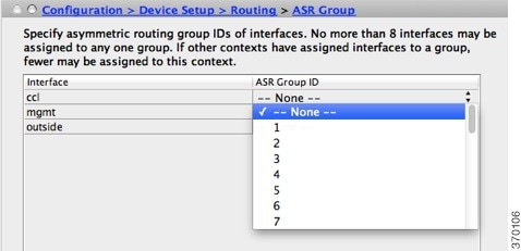
Step 2![]() For the interface that receives asymmetrically routed packets, choose an ASR group number from the drop-down list.
For the interface that receives asymmetrically routed packets, choose an ASR group number from the drop-down list.
Step 3![]() Click Apply to save your changes to the running configuration.
Click Apply to save your changes to the running configuration.
Step 4![]() Connect ASDM to the secondary unit, and choose the active context similar to the primary unit context.
Connect ASDM to the secondary unit, and choose the active context similar to the primary unit context.
Step 5![]() Choose Configuration > Device Setup > Routing > ASR Groups.
Choose Configuration > Device Setup > Routing > ASR Groups.
Step 6![]() For the similar interface on this unit, choose the same ASR group number.
For the similar interface on this unit, choose the same ASR group number.
Step 7![]() Click Apply to save your changes to the running configuration.
Click Apply to save your changes to the running configuration.
Managing Failover
- Modifying the Failover Setup
- Forcing Failover
- Disabling Failover
- Restoring a Failed Unit
- Re-Syncing the Configuration
Modifying the Failover Setup
If you do not use the wizard, or want to change a setting, you can configure the failover setup manually. This section also includes the following options that are not included in the wizard, so you must configure them manually:
Prerequisites
In multiple context mode, perform this procedure in the System execution space.
Detailed Steps
Step 1![]() In single mode, choose Configuration > Device Management > High Availability and Scalability > Failover > Setup.
In single mode, choose Configuration > Device Management > High Availability and Scalability > Failover > Setup.
In multiple context mode, choose Configuration > Device Management > Failover > Setup in the System execution space.
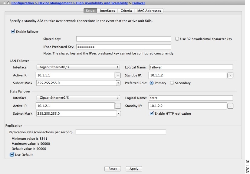
Step 2![]() Check the Enable Failover check box.
Check the Enable Failover check box.
Note![]() Failover is not actually enabled until you apply your changes to the device.
Failover is not actually enabled until you apply your changes to the device.
Step 3![]() To encrypt communications on the failover and state links, use one of the following options:
To encrypt communications on the failover and state links, use one of the following options:
- IPsec Preshared Key (preferred)—The preshared key is used by IKEv2 to establish IPsec LAN-to-LAN tunnels on the failover links between the failover units. Note: failover LAN-to-LAN tunnels do not count against the IPsec (Other VPN) license.
- Secret Key—Enter the secret key used to encrypt failover communication. If you leave this field blank, failover communication, including any passwords or keys in the configuration that are sent during command replication, will be in clear text.
Use 32 hexadecimal character key—To use a 32-hexadecimal key for the secret key, check this check box.
Step 4![]() In the LAN Failover area, set the following parameters for the failover link:
In the LAN Failover area, set the following parameters for the failover link:
- Interface—Choose the interface to use for the failover link. Failover requires a dedicated interface, however you can share the interface with Stateful Failover.
Only unconfigured interfaces or subinterfaces are displayed in this list and can be selected as the failover link. Once you specify an interface as the failover link, you cannot edit that interface in the Configuration > Interfaces pane.
- Logical Name—Specify the logical name of the interface used for failover communication, such as “failover”. This name is informational.
- Active IP—Specify the active IP address for the interface. The IP address can be either an IPv4 or an IPv6 address. This IP address should be on an unused subnet.
- Standby IP—Specify the standby IP address for the interface, on the same subnet as the active IP address.
- Subnet Mask—Specify the subnet mask.
- Preferred Role—Select Primary or Secondary to specify whether the preferred role for this ASA is as the primary or secondary unit.
Step 5![]() (Optional) Configure the state link by doing the following:
(Optional) Configure the state link by doing the following:
- Interface—Choose the interface to use for the state link. You can choose an unconfigured interface or subinterface, the failover link, or the --Use Named-- option.
Note![]() We recommend that you use two separate, dedicated interfaces for the failover link and the state link.
We recommend that you use two separate, dedicated interfaces for the failover link and the state link.
If you choose an unconfigured interface or subinterface, you must supply the Active IP, Subnet Mask, Standby IP, and Logical Name for the interface.
If you choose the failover link, you do not need to specify the Active IP, Subnet Mask, Logical Name, and Standby IP values; the values specified for the failover link are used.
If you choose the --Use Named-- option, the Logical Name field becomes a drop-down list of named interfaces. Choose the interface from this list. The Active IP, Subnet Mask/Prefix Length, and Standby IP values do not need to be specified. The values specified for the interface are used.
- Logical Name—Specify the logical name of the interface used for state communication, such as “state”. This name is informational.
- Active IP—Specify the active IP address for the interface. The IP address can be either an IPv4 or an IPv6 address. This IP address should be on an unused subnet, different from the failover link.
- Standby IP—Specify the standby IP address for the interface, on the same subnet as the active IP address.
- Subnet Mask—Specify the subnet mask.
- (Optional, Active/Standby only) Enable HTTP Replication—Enable HTTP replication by checking the Enable HTTP Replication check box. This option enables Stateful Failover to copy active HTTP sessions to the standby firewall. If you do not allow HTTP replication, then HTTP connections are disconnected in the event of a failover. In Active/Active mode, set the HTTP replication per failover group. See Configuring Failover Criteria, HTTP Replication, Group Preemption, and MAC Addresses.
Step 6![]() In the Replication area, set the HTTP replication rate between 8341 connections per second and 50000. The default is 50000. To use the default, check the Use Default check box.
In the Replication area, set the HTTP replication rate between 8341 connections per second and 50000. The default is 50000. To use the default, check the Use Default check box.
The configuration is saved to the device.
Step 8![]() If you are enabling failover, you see a dialog box to configure the failover peer.
If you are enabling failover, you see a dialog box to configure the failover peer.
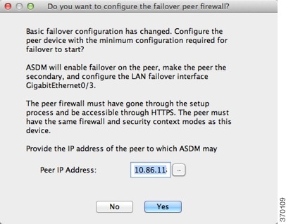
Forcing Failover
To force the standby unit to become active, perform the following procedure.
Prerequisites
In multiple context mode, perform this procedure in the System execution space.
Detailed Steps
Step 1![]() To force failover at the unit level:
To force failover at the unit level:
a.![]() Choose the screen depending on your context mode:
Choose the screen depending on your context mode:
- In single context mode choose Monitoring > Properties > Failover > Status.
- In multiple context mode, in the System choose Monitoring > Failover > System.
b.![]() Click one of the following buttons:
Click one of the following buttons:
Step 2![]() (Active/Active mode only) To force failover at the failover group level:
(Active/Active mode only) To force failover at the failover group level:
a.![]() In the System choose Monitoring > Failover > Failover Group #, where # is the number of the failover group you want to control.
In the System choose Monitoring > Failover > Failover Group #, where # is the number of the failover group you want to control.
b.![]() Click one of the following buttons:
Click one of the following buttons:
Disabling Failover
Prerequisites
In multiple context mode, perform this procedure in the System execution space.
Detailed Steps
Step 1![]() In single mode, choose Configuration > Device Management > High Availability and Scalability > Failover > Setup.
In single mode, choose Configuration > Device Management > High Availability and Scalability > Failover > Setup.
In multiple context mode, choose Configuration > Device Management > Failover > Setup in the System execution space.
Step 2![]() Uncheck the Enable Failover check box.
Uncheck the Enable Failover check box.
Restoring a Failed Unit
To restore a failed unit to an unfailed state, perform the following procedure.
Prerequisites
In multiple context mode, perform this procedure in the System execution space.
Detailed Steps
Step 1![]() To restore failover at the unit level:
To restore failover at the unit level:
a.![]() Choose the screen depending on your context mode:
Choose the screen depending on your context mode:
- In single context mode choose Monitoring > Properties > Failover > Status.
- In multiple context mode, in the System choose Monitoring > Failover > System.
Step 2![]() (Active/Active mode only) To reset failover at the failover group level:
(Active/Active mode only) To reset failover at the failover group level:
a.![]() In the System choose Monitoring > Failover > Failover Group #, where # is the number of the failover group you want to control.
In the System choose Monitoring > Failover > Failover Group #, where # is the number of the failover group you want to control.
Re-Syncing the Configuration
Replicated commands are stored in the running configuration. To save replicated commands to the flash memory on the standby unit, choose File > Save Running Configuration to Flash.
Monitoring Failover
Failover Messages
When a failover occurs, both ASAs send out system messages. This section includes the following topics:
Failover Syslog Messages
The ASA issues a number of syslog messages related to failover at priority level 2, which indicates a critical condition. To view these messages, see the syslog messages guide. To enable logging, see Chapter45, “Logging”
Note![]() During a fail over, failover logically shuts down and then bring up interfaces, generating syslog messages 411001 and 411002. This is normal activity.
During a fail over, failover logically shuts down and then bring up interfaces, generating syslog messages 411001 and 411002. This is normal activity.
Failover Debug Messages
To see debug messages, enter the debug fover command. See the command reference for more information.
Note![]() Because debugging output is assigned high priority in the CPU process, it can drastically affect system performance. For this reason, use the debug fover commands only to troubleshoot specific problems or during troubleshooting sessions with Cisco TAC.
Because debugging output is assigned high priority in the CPU process, it can drastically affect system performance. For this reason, use the debug fover commands only to troubleshoot specific problems or during troubleshooting sessions with Cisco TAC.
SNMP Failover Traps
To receive SNMP syslog traps for failover, configure the SNMP agent to send SNMP traps to SNMP management stations, define a syslog host, and compile the Cisco syslog MIB into your SNMP management station. See Chapter 46, “SNMP” for more information.
Monitoring Failover
Note![]() After a failover event you should either re-launch ASDM or switch to another device in the Devices pane and then come back to the original ASA to continue monitoring the device. This action is necessary because the monitoring connection does not become re-established when ASDM is disconnected from and then reconnected to the device.
After a failover event you should either re-launch ASDM or switch to another device in the Devices pane and then come back to the original ASA to continue monitoring the device. This action is necessary because the monitoring connection does not become re-established when ASDM is disconnected from and then reconnected to the device.
Choose Monitoring > Properties > Failover to monitor Active/Standby failover.
Use the following screens in the Monitoring > Properties > Failover area to monitor Active/Active failover:
System
The System pane displays the failover state of the system. You can also control the failover state of the system by:
- Toggling the active/standby state of the device.
- Resetting a failed device.
- Reloading the standby unit.
Failover state of the system— Display only. Displays the failover state of the ASA. The information shown is the same output you would receive from the show failover command. Refer to the command reference for more information about the displayed output.
The following actions are available on the System pane:
- Make Active—Click this button to make the ASA the active unit in an active/standby configuration. In an active/active configuration, clicking this button causes both failover groups to become active on the ASA.
- Make Standby—Click this button to make the ASA the standby unit in an active/standby pair. In an active/active configuration, clicking this button causes both failover groups to go to the standby state on the ASA.
- Reset Failover—Click this button to reset a system from the failed state to the standby state. You cannot reset a system to the active state. Clicking this button on the active unit resets the standby unit.
- Reload Standby—Click this button to force the standby unit to reload.
- Refresh—Click this button to refresh the status information in the Failover state of the system field.
Failover Group 1 and Failover Group 2
The Failover Group 1 and Failover Group 2 panes display the failover state of the selected group.You can also control the failover state of the group by toggling the active/standby state of the group or by resetting a failed group.
Failover state of Group[ x ]— Display only. Displays the failover state of the selected failover group. The information shown is the same as the output you would receive from the show failover group command.
You can perform the following actions from this pane:
- Make Active—Click this button to make the failover group active unit on the ASA.
- Make Standby—Click this button to force the failover group into the standby state on the ASA.
- Reset Failover—Click this button to reset a system from the failed state to the standby state. You cannot reset a system to the active state. Clicking this button on the active unit resets the standby unit.
- Refresh—Click this button to refresh the status information in the Failover state of the system field.
Feature History for Failover
Table 8-4 lists the release history for this feature.
 Feedback