Overview of Collapsed Forwarding
Cisco multi-switch edge (MSE) solution leverages the capabilities of the Cisco NCS 6000 series router to host multiple logical SDRs which can act as core or edge routers based on how the SDRs are configured.
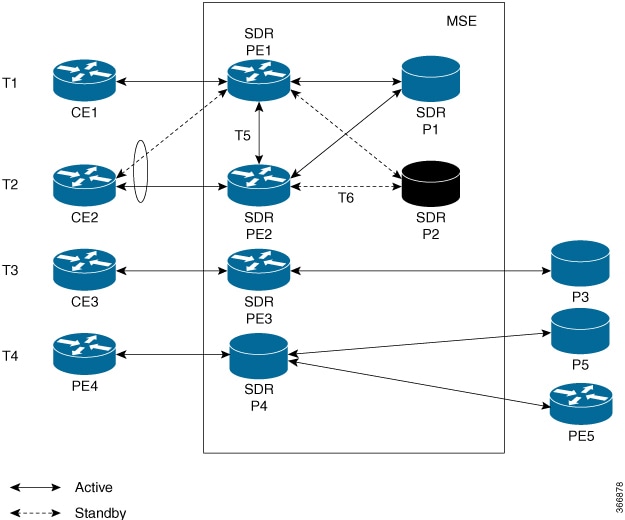
The following figure specifies all the possible topologies supported by the Cisco MSE solution.
-
Topology T1-In this topology, all the PE SDRs converge to a common core router P1 to achieve statistical multiplexing gain.
-
Topology T2- This topology is to support redundancy at the service provider edge (dual homing) or can be also used for load balancing.
-
Topology T3 - In this topology, the service edge router converges to the external core router, outside the MSE.
-
Topology T4 - In this topology, external edge router converges to the core router inside the MSE.
-
Topology T5 - This topology is used for edge router connectivity for terminating the traffic without going to the core internal router.
-
Topology T6 - This topology is to support core router redundancy. In case P1 router goes down, P2 as redundant router runs with the same configuration.
For forwarding traffic from one SDR to another SDR, the existing solution was to connect the SDRs using external cables and ports. This approach is not cost effective for the service providers since it reduces the availability of ports for services. To overcome this issue, Cisco MSE solution uses another approach known as collapsed forwarding.
In collapsed forwarding, inter SDR traffic is handled by the internal fabric itself without requiring the external cables. A newly created SDR interface functions as a point-to-point virtual interface, connecting SDR routers in the system. This virtual interface that connects two SDRs to each other is known as cross SDR interconnect (CSI) interface.
Supported Features and Restrictions
This section provides information about the supported features and restrictions for collapsed forwarding configuration.
-
The CSI interface is a point-to-point interface that can be configured with IPv4 or IPv6 address.
-
Only routing protocols, MPLS, and multicast can be configured over the CSI interface.
-
QoS, ACL, and NetFlow are not supported over the CSI interface.
-
Sub interfaces of VLANs for CSI interface is not supported.
-
For a system, only up to 15 CSI interfaces are supported.
Configuring Collapsed Forwarding
Configuring collapsed forwarding includes the following steps.
-
Create named SDRs using the system administration configuration mode.
-
Configure the CSI interface using the system administration configuration mode.
-
Assign the IP addresses for the CSI interface on the required SDRs from XR configuration mode.
-
Configure the routing protocols between SDR1 and SDR2 over the CSI interface.
Example: Creating Named SDRs
This example shows how to create named SDRs. In this example, two named SDRs, SDR1 and SDR2 are created and RP resources and line cards are allocated to the SDRs.
sysadmin-vm:0_RP0(config)# sdr sdr1
sysadmin-vm:0_RP0(config-sdr-sdr1)# resources mgmt_ext_vlan 11
sysadmin-vm:0_RP0(config-sdr-sdr1)# resources card-type RP
sysadmin-vm:0_RP0(config-card-type-RP)#	vm-memory 11
sysadmin-vm:0_RP0(config-card-type-RP)#	vm-cpu	4
sysadmin-vm:0_RP0(config-card-type-RP)# location 0/RP0
sysadmin-vm:0_RP0(config-location-0/RP0)# location 0/RP1
sysadmin-vm:0_RP0(config-location-0/RP1)# exit
sysadmin-vm:0_RP0(config-sdr-sdr1)# location 0/0
sysadmin-vm:0_RP0(config-sdr-sdr1)# commit
sysadmin-vm:0_RP0(config)# sdr sdr2
sysadmin-vm:0_RP0(config-sdr-sdr2)# resources mgmt_ext_vlan 12
sysadmin-vm:0_RP0(config-sdr-sdr2)# resources card-type RP
sysadmin-vm:0_RP0(config-card-type-RP)#	vm-memory 11
sysadmin-vm:0_RP0(config-card-type-RP)#	vm-cpu	4
sysadmin-vm:0_RP0(config-sdr-sdr2)# location 0/RP0
sysadmin-vm:0_RP0(config-location-0/RP0)# location 0/RP1
sysadmin-vm:0_RP0(config-location-0/RP1)# exit
sysadmin-vm:0_RP0(config-sdr-sdr2)# location 0/1
sysadmin-vm:0_RP0(config-sdr-sdr2)# commit
sysadmin-vm:0_RP0# config
sysadmin-vm:0_RP0(config)# console attach-sdr location 0/RP0 tty-name console1 sdr-name SDR1
sysadmin-vm:0_RP0(config)# console attach-sdr location 0/RP1 tty-name console1 sdr-name SDR1
sysadmin-vm:0_RP0(config)# console attach-sdr location 0/RP0 tty-name console2 sdr-name SDR2
sysadmin-vm:0_RP0(config)# console attach-sdr location 0/RP1 tty-name console2 sdr-name SDR2
sysadmin-vm:0_RP0(config)# commit
For detailed information about configuring named SDRs, see Setup Console Access for Named-SDR.
Example: Configuring the CSI Interface
This example shows how to configure the CSI interface between two SDRs. When you perform this task, a single point-to-point link is created with one endpoint in SDR1 (called csi1 in SDR1) and the other endpoint in SDR2 (also called csi1 in SDR2). You can configure up to 15 CSI interfaces and the CSI-ID can be a number from 1 to 15.
sysadmin-vm:0_RP0(config)# connect sdr sdr1 sdr2 csi-id 1
Example: Configuring IP addresses on the CSI Interfaces
Once the CSI interface is created, you need to configure IP addresses for the CSI interface on the inter connected SDRs using the XR configuration mode.
This example shows how to configure IPv4 addresses on the CSI interface on SDR1.
RP/0/RP0/CPU1:router(config)# interface csi 1
RP/0/RP0/CPU1:router(config-if)# ipv4 address 1.1.1.1 255.255.255.0
RP/0/RP0/CPU1:router(config-if)# exit
RP/0/RP0/CPU1:router(config)# commit
This example shows how to configure IPv4 addresses on the CSI interface on SDR2.
RP/0/RP0/CPU2:router(config)# interface csi 1
RP/0/RP0/CPU2:router(config-if)# ipv4 address 1.1.1.2 255.255.255.0
RP/0/RP0/CPU1:router(config-if)# exit
Example: Configuring the Routing Protocols
This example shows how to configure a routing protocol over the CSI interface. In this example, IS-IS is used as the routing protocol. You need to configure IS-IS on SDR1 and SDR2.
RP/0/RP0/CPU1:router(config)# router isis 1
RP/0/RP0/CPU1:router(config-isis)# is-type level-2-only
RP/0/RP0/CPU1:router(config-isis)# net 49.0001.0001.0001.0001.00
RP/0/RP0/CPU1:router(config-isis)# address-family ipv4 unicast
RP/0/RP0/CPU1:router(config-isis-af)# metric-style wide level 1
RP/0/RP0/CPU1:router(config-isis-af)# exit
RP/0/RP0/CPU1:router(config-isis)# interface csi 1
RP/0/RP0/CPU1:router(config-isis-if)# address-family ipv4 unicast
RP/0/RP0/CPU1:router(config-isis-if-af)# exit
RP/0/RP0/CPU1:router(config-isis-if)# exit
Verifying the CSI Interface Configuration
You can verify the CSI interface configuration by using the ping command to verify the connectivity to the CSI from the SDR.
This example shows verifying the CSI interface configuration from SDR1 using the ping command.
RP/0/RP0/CPU1:router# ping 1.1.1.2
Sending 5, 100-byte ICMP Echos to 1.1.1.2, timeout is 2 seconds:
!!!!!
Success rate is 100 percent (5/5), round-trip min/avg/max = 99/184/431 ms
This example shows verifying the CSI interface configuration from SDR2 using the ping command.
RP/0/RP0/CPU2:router# ping 1.1.1.1
Sending 5, 100-byte ICMP Echos to 1.1.1.1, timeout is 2 seconds:
!!!!!
Success rate is 100 percent (5/5), round-trip min/avg/max = 60/125/264 ms Feedback