MPLS Configuration Guide for Cisco NCS 6000 Series Routers, Release 6.1.x
Bias-Free Language
The documentation set for this product strives to use bias-free language. For the purposes of this documentation set, bias-free is defined as language that does not imply discrimination based on age, disability, gender, racial identity, ethnic identity, sexual orientation, socioeconomic status, and intersectionality. Exceptions may be present in the documentation due to language that is hardcoded in the user interfaces of the product software, language used based on RFP documentation, or language that is used by a referenced third-party product. Learn more about how Cisco is using Inclusive Language.
The Multiprotocol Label Switching (MPLS) is a standards-based solution driven by the Internet Engineering Task Force (IETF)
that was devised to convert the Internet and IP backbones from best-effort networks into business-class transport mediums.
MPLS, with its label switching capabilities, eliminates the need for an IP route look-up and creates a virtual circuit (VC)
switching function, allowing enterprises the same performance on their IP-based network services as with those delivered over
traditional networks such as Frame Relay or ATM.
Label Distribution Protocol (LDP) performs label distribution in MPLS environments. LDP provides the following capabilities:
LDP performs hop-by-hop or dynamic path setup; it does not provide end-to-end switching services.
LDP assigns labels to routes using the underlying Interior Gateway Protocols (IGP) routing protocols.
LDP provides constraint-based routing using LDP extensions for traffic engineering.
Finally, LDP is deployed in the core of the network and is one of the key protocols used in MPLS-based Layer 2 and Layer 3
virtual private networks (VPNs).
Feature History for Implementing MPLS LDP
Release
Modification
Release 5.0.0
This feature was introduced.
Release 7.1.1
Multiple MPLS-TE tunnel end points can be enabled on an LER using the TLV 132 function in IS-IS.
Prerequisites for Implementing Cisco MPLS LDP
These prerequisites are required to implement MPLS LDP:
You must be in a user group associated with a task group that includes the proper task IDs. The command reference guides include
the task IDs required for each command. If you suspect user group assignment is preventing you from using a command, contact
your AAA administrator for assistance.
You must be running
Cisco IOS XR software.
You must install a composite mini-image and the MPLS package.
You must activate IGP.
We recommend to use a lower session holdtime bandwidth such as neighbors so that a session down occurs before an adjacency-down
on a neighbor. Therefore, the following default values for the hello times are listed:
Holdtime is 15 seconds.
Interval is 5 seconds.
For example, the LDP session holdtime can be configured as 30 seconds by using the holdtime command.
Information About Implementing Cisco MPLS LDP
To implement MPLS LDP, you should understand these concepts:
Overview of Label Distribution Protocol
LDP performs label distribution in MPLS environments. LDP uses hop-by-hop or dynamic path setup, but does not provide end-to-end
switching services. Labels are assigned to routes that are chosen by the underlying IGP routing protocols. The Label Switched
Paths (LSPs) that result from the routes, forward labeled traffic across the MPLS backbone to adjacent nodes.
Label Switched Paths
LSPs are created in the network through MPLS. They can be created statically, by RSVP traffic engineering (TE), or by LDP.
LSPs created by LDP perform hop-by-hop path setup instead of an end-to-end path.
LDP Control
Plane
The control plane
enables label switched routers (LSRs) to discover their potential peer routers
and to establish LDP sessions with those peers to exchange label binding
information.
Exchanging Label Bindings
LDP creates LSPs to perform the hop-by-hop path setup so that MPLS
packets can be transferred between the nodes on the MPLS network.
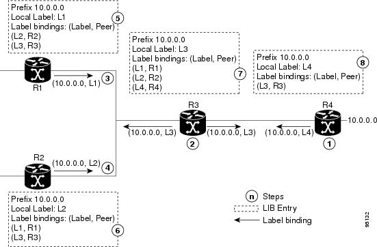
Figure 1. Setting Up Label Switched Paths .
This figure illustrates the process of label binding exchange for setting up LSPs.
For a given network (10.0.0.0), hop-by-hop LSPs are set up between each
of the adjacent routers (or, nodes) and each node allocates a local label and
passes it to its neighbor as a binding:
R4 allocates local label L4 for prefix 10.0.0.0 and advertises it to
its neighbors (R3).
R3 allocates local label L3 for prefix 10.0.0.0 and advertises it to
its neighbors (R1, R2, R4).
R1 allocates local label L1 for prefix 10.0.0.0 and advertises it to
its neighbors (R2, R3).
R2 allocates local label L2 for prefix 10.0.0.0 and advertises it to
its neighbors (R1, R3).
R1’s label information base (LIB) keeps local and remote labels
bindings from its neighbors.
R2’s LIB keeps local and remote labels bindings from its neighbors.
R3’s LIB keeps local and remote labels bindings from its neighbors.
R4’s LIB keeps local and remote labels bindings from its neighbors.
LDP
Forwarding
Once label bindings
are learned, the LDP control plane is ready to setup the MPLS forwarding plane
as shown in the following figure.
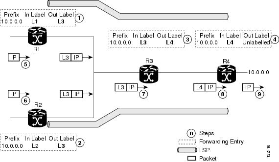
Figure 2. Forwarding
Setup. Once label
bindings are learned, the LDP control plane is ready to setup the MPLS
forwarding plane as shown in this figure.
Because R3 is next
hop for 10.0.0.0 as notified by the FIB, R1 selects label binding from R3 and
installs forwarding entry (Layer 1, Layer 3).
Because R3 is next
hop for 10.0.0.0 (as notified by FIB), R2 selects label binding from R3 and
installs forwarding entry (Layer 2, Layer 3).
Because R4 is next
hop for 10.0.0.0 (as notified by FIB), R3 selects label binding from R4 and
installs forwarding entry (Layer 3, Layer 4).
Because next hop
for 10.0.0.0 (as notified by FIB) is beyond R4, R4 uses NO-LABEL as the
outbound and installs the forwarding entry (Layer 4); the outbound packet is
forwarded IP-only.
Incoming IP
traffic on ingress LSR R1 gets label-imposed and is forwarded as an MPLS packet
with label L3.
Incoming IP
traffic on ingress LSR R2 gets label-imposed and is forwarded as an MPLS packet
with label L3.
R3 receives an
MPLS packet with label L3, looks up in the MPLS label forwarding table and
switches this packet as an MPLS packet with label L4.
R4 receives an
MPLS packet with label L4, looks up in the MPLS label forwarding table and
finds that it should be Unlabeled, pops the top label, and passes it to the IP
forwarding plane.
IP forwarding
takes over and forwards the packet onward.
Note
For local labels,
only up to 12000 rewrites are supported. If the rewrites exceed this limit,
MPLS LSD or MPLS LDP or both the processes may crash.
LDP Graceful Restart
LDP (Label Distribution Protocol) graceful restart provides a control plane mechanism to ensure high
availability and allows detection and recovery from failure conditions while
preserving Nonstop Forwarding (NSF) services. Graceful restart is a way to
recover from signaling and control plane failures without impacting forwarding.
Without LDP graceful restart, when an established session fails, the
corresponding forwarding states are cleaned immediately from the restarting and
peer nodes. In this case LDP forwarding restarts from the
beginning, causing a potential loss of data and connectivity.
The LDP graceful restart capability is negotiated between two peers
during session initialization time, in FT SESSION TLV. In this typed length
value (TLV), each peer advertises the following information to its peers:
Reconnect time
Advertises the maximum time that other peer will wait for this LSR
to reconnect after control channel failure.
Recovery time
Advertises the maximum time that the other peer has on its side to
reinstate or refresh its states with this LSR. This time is used only during
session reestablishment after earlier session failure.
FT flag
Specifies whether a restart could restore the preserved (local)
node state for this flag.
Once the graceful restart session parameters are conveyed and the
session is up and running, graceful restart procedures are activated.
When configuring the LDP graceful restart process in a network with multiple links, targeted LDP hello adjacencies with the
same neighbor, or both, make sure that graceful restart is activated on the session before any hello adjacency times out in
case of neighbor control plane failures. One way of achieving this is by configuring a lower session hold time between neighbors
such that session timeout occurs before hello adjacency timeout. It is recommended to set LDP session hold time using the
following formula:
This means that for default values of 15 seconds and 5 seconds for link Hello holdtime and interval respectively, session
hold time should be set to 30 seconds at most.
For more information about LDP commands, see MPLS Label Distribution Protocol Commands module of the
MPLS Command Reference for Cisco NCS 6000 Series Routers.
Control Plane Failure
When a control plane failure occurs, connectivity can be affected. The
forwarding states installed by the router control planes are lost, and the
in-transit packets could be dropped, thus breaking NSF.
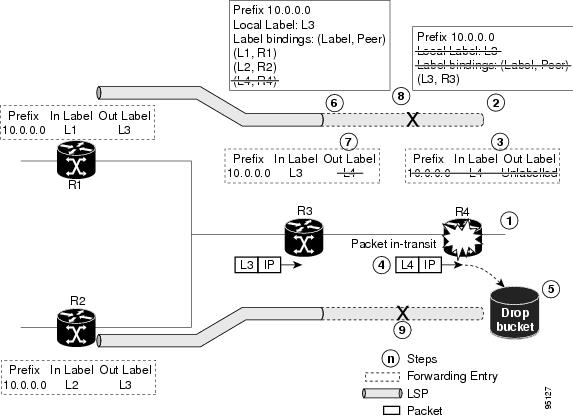
Figure 3. Control Plane Failure. This figure illustrates a control plane failure and shows the process and results of a
control plane failure leading to loss of connectivity.
The R4 LSR control plane restarts.
LIB is lost when the control plane restarts.
The forwarding states installed by the R4 LDP control plane are
immediately deleted.
Any in-transit packets flowing from R3 to R4 (still labeled with L4)
arrive at R4.
The MPLS forwarding plane at R4 performs a lookup on local label L4
which fails. Because of this failure, the packet is dropped and NSF is not met.
The R3 LDP peer detects the failure of the control plane channel and
deletes its label bindings from R4.
The R3 control plane stops using outgoing labels from R4 and deletes
the corresponding forwarding state (rewrites), which in turn causes forwarding
disruption.
The established LSPs connected to R4 are terminated at R3, resulting
in broken end-to-end LSPs from R1 to R4.
The established LSPs connected to R4 are terminated at R3, resulting
in broken LSPs end-to-end from R2 to R4.
Phases in Graceful Restart
The graceful restart mechanism is divided into different phases:
Control communication failure detection
Control communication failure is detected when the system detects either:
Missed LDP hello discovery messages
Missed LDP keepalive protocol messages
Detection of Transmission Control Protocol (TCP) disconnection a with a peer
Forwarding state maintenance during failure
Persistent forwarding states at each LSR are achieved through persistent storage (checkpoint) by the LDP control plane. While
the control plane is in the process of recovering, the forwarding plane keeps the forwarding states, but marks them as stale.
Similarly, the peer control plane also keeps (and marks as stale) the installed forwarding rewrites associated with the node
that is restarting. The combination of local node forwarding and remote node forwarding plane states ensures NSF and no disruption
in the traffic.
Control state recovery
Recovery occurs when the session is reestablished and label bindings are exchanged again. This process allows the peer nodes
to synchronize and to refresh stale forwarding states.
Recovery with Graceful-Restart
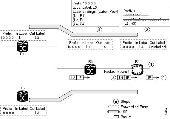
Figure 4. Recovering with Graceful Restart. This figure
illustrates the process of failure recovery using graceful restart.
The router R4 LSR control plane restarts.
With the control plane restart, LIB is gone but forwarding states
installed by R4’s LDP control plane are not immediately deleted but are marked
as stale.
Any in-transit packets from R3 to R4 (still labeled with L4) arrive
at R4.
The MPLS forwarding plane at R4 performs a successful lookup for the
local label L4 as forwarding is still intact. The packet is forwarded
accordingly.
The router R3 LDP peer detects the failure of the control plane and
channel and deletes the label bindings from R4. The peer, however, does not
delete the corresponding forwarding states but marks them as stale.
At this point there are no forwarding disruptions.
The peer also starts the neighbor reconnect timer using the
reconnect time value.
The established LSPs going toward the router R4 are still intact,
and there are no broken LSPs.
When the LDP control plane recovers, the restarting LSR starts its
forwarding state hold timer and restores its forwarding state from the
checkpointed data. This action reinstates the forwarding state and entries and
marks them as old.
The restarting LSR reconnects to its peer, indicated in the FT Session
TLV, that it either was or was not able to restore its state successfully. If
it was able to restore the state, the bindings are resynchronized.
The peer LSR stops the neighbor reconnect timer (started by the
restarting LSR), when the restarting peer connects and starts the neighbor
recovery timer. The peer LSR checks the FT Session TLV if the restarting peer
was able to restore its state successfully. It reinstates the corresponding
forwarding state entries and receives binding from the restarting peer. When
the recovery timer expires, any forwarding state that is still marked as stale
is deleted.
If the restarting LSR fails to recover (restart), the restarting LSR
forwarding state and entries will eventually timeout and is deleted, while
neighbor-related forwarding states or entries are removed by the Peer LSR on
expiration of the reconnect or recovery timers.
Label Advertisement Control (Outbound Filtering)
By default, LDP advertises labels for all the prefixes to all its
neighbors. When this is not desirable (for scalability and security reasons),
you can configure LDP to perform outbound filtering for local label
advertisement for one or more prefixes to one more peers. This feature is known
as
LDP outbound label filtering, or
local label advertisement control.
Label Acceptance Control (Inbound Filtering)
By default, LDP accepts labels (as remote bindings) for all prefixes from all peers. LDP operates in liberal label retention
mode, which instructs LDP to keep remote bindings from all peers for a given prefix. For security reasons, or to conserve
memory, you can override this behavior by configuring label binding acceptance for set of prefixes from a given peer.
The ability to filter remote bindings for a defined set of prefixes is also referred to as LDP inbound label filtering.
Note
Inbound filtering can also be implemented using an outbound filtering policy; however, you may not be able to implement this
system if an LDP peer resides under a different administration domain. When both inbound and outbound filtering options are
available, we recommend that you use outbound label filtering.
Local Label Allocation Control
By default, LDP allocates local labels for all prefixes that are not Border Gateway Protocol (BGP) prefixes1. This is acceptable when LDP is used for applications other than Layer 3 virtual private networks (L3VPN) core transport.
When LDP is used to set up transport LSPs for L3VPN traffic in the core, it is not efficient or even necessary to allocate
and advertise local labels for, potentially, thousands of IGP prefixes. In such a case, LDP is typically required to allocate
and advertise local label for loopback /32 addresses for PE routers. This is accomplished using LDP local label allocation
control, where an access list can be used to limit allocation of local labels to a set of prefixes. Limiting local label allocation
provides several benefits, including reduced memory usage requirements, fewer local forwarding updates, and fewer network
and peer updates.
Tip
You can configure label allocation using an IP access list to specify a set of prefixes that local labels can allocate and
advertise.
Session Protection
When a link comes up, IP converges earlier and much faster than MPLS LDP
and may result in MPLS traffic loss until MPLS convergence. If a link flaps,
the LDP session will also flap due to loss of link discovery. LDP session
protection minimizes traffic loss, provides faster convergence, and protects
existing LDP (link) sessions by means of “parallel” source of targeted
discovery hello. An LDP session is kept alive and neighbor label bindings are
maintained when links are down. Upon reestablishment of primary link
adjacencies, MPLS convergence is expedited as LDP need not relearn the neighbor
label bindings.
LDP session protection lets you configure LDP to automatically protect
sessions with all or a given set of peers (as specified by peer-acl). When
configured, LDP initiates backup targeted hellos automatically for neighbors
for which primary link adjacencies already exist. These backup targeted hellos
maintain LDP sessions when primary link adjacencies go down.
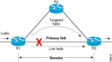
The Session Protection figure
illustrates LDP session protection between neighbors R1 and R3. The primary
link adjacency between R1 and R3 is directly connected link and the backup;
targeted adjacency is maintained between R1 and R3. If the direct link fails,
LDP link adjacency is destroyed, but the session is kept up and running using
targeted hello adjacency (through R2). When the direct link comes back up,
there is no change in the LDP session state and LDP can converge quickly and
begin forwarding MPLS traffic.
Figure 5. Session Protection
Note
When LDP session protection is activated (upon link failure),
protection is maintained for an unlimited period time.
IGP Synchronization
Lack of synchronization between LDP and IGP can cause MPLS traffic loss. Upon link up, for example, IGP can advertise and
use a link before LDP convergence has occurred; or, a link may continue to be used in IGP after an LDP session goes down.
LDP IGP synchronization synchronizes LDP and IGP so that IGP advertises links with regular metrics only when MPLS LDP is converged
on that link. LDP considers a link converged when at least one LDP session is up and running on the link for which LDP has
sent its applicable label bindings and received at least one label binding from the peer. LDP communicates this information
to IGP upon link up or session down events and IGP acts accordingly, depending on sync state.
In the event of an LDP graceful restart session disconnect, a session is treated as converged as long as the graceful restart
neighbor is timed out. Additionally, upon local LDP restart, a checkpointed recovered LDP graceful restart session is used
and treated as converged and is given an opportunity to connect and resynchronize.
Under certain circumstances, it might be required to delay declaration of resynchronization to a configurable interval. LDP
provides a configuration option to delay declaring synchronization up for up to 60 seconds. LDP communicates this information
to IGP upon linkup or session down events.
Note
The configuration for LDP IGP synchronization resides in respective IGPs (OSPF and IS-IS) and there is no LDP-specific configuration
for enabling of this feature. However, there is a specific LDP configuration for IGP sync delay timer.
IGP Auto-configuration
To enable LDP on a large number of interfaces, IGP auto-configuration lets you automatically configure LDP on all interfaces
associated with a specified IGP interface; for example, when LDP is used for transport in the core network. However, there
needs to be one IGP set up to enable LDP auto-configuration.
Typically, LDP assigns and advertises labels for IGP routes and must often be enabled on all active interfaces by an IGP.
Without IGP auto-configuration, you must define the set of interfaces under LDP, a procedure that is time-intensive and error-prone.
Note
LDP auto-configuration is supported for IPv4 unicast family in the default VRF. The IGP is responsible for verifying and applying
the configuration.
You can also disable auto-configuration on a per-interface basis. This permits LDP to enable all IGP interfaces except those
that are explicitly disabled and prevents LDP from enabling an interface when LDP auto-configuration is configured under IGP.
LDP Nonstop
Routing
LDP nonstop routing
(NSR) functionality makes failures, such as Route Processor (RP) or Distributed
Route Processor (DRP) failover, invisible to routing peers with minimal to no
disruption of convergence performance. By default, NSR is globally enabled on
all LDP sessions except AToM.
A disruption in
service may include any of these events:
Route processor
(RP) or distributed route processor (DRP) failover
LDP process
restart
In-service system
upgrade (ISSU)
Minimum disruption
restart (MDR)
Note
Unlike graceful
restart functionality, LDP NSR does not require protocol extensions and does
not force software upgrades on other routers in the network, nor does LDP NSR
require peer routers to support NSR.
Process failures of
active TCP or LDP results in session loss and, as a result, NSR cannot be
provided unless RP switchover is configured as a recovery action. For more
information about how to configure switchover as a recovery action for NSR, see
Configuring
Transports module in
IP Addresses and Services Configuration Guide for Cisco NCS 6000 Series Routers.
IP LDP Fast Reroute Loop Free Alternate
The IP Fast Reroute is
a mechanism that enables a router to rapidly switch traffic,
after an adjacent link failure, node failure, or both, towards a
pre-programmed loop-free alternative (LFA) path. This
LFA path is used to switch traffic until the router installs a
new primary next hop again, as computed for the changed network
topology.
The goal of LFA FRR is to reduce failure reaction time to 50 milliseconds by using a pre-computed alternate next hop, in the
event that the currently selected primary next hop fails, so that
the alternate can be rapidly used when the failure is detected.
This feature targets to address the fast convergence ability by detecting, computing, updating or enabling prefix independent
pre-computed alternate loop-free paths at the time of failure.
IGP pre-computes a backup path per IGP prefix. IGP selects one and only one backup path per primary path. RIB installs the
best path and download path protection information to FIB by providing correct annotation for protected and
protecting paths. FIB pre-installs the backup path in dataplane. Upon the link or node failure, the routing protocol detects
the failure, all the backup paths of the impacted prefixes are enabled in a prefix-independent manner.
Prerequisites
The Label Distribution Protocol (LDP) can use the loop-free alternates as long as these prerequisites are met:
The Label Switching Router (LSR) running LDP must distribute its labels for the Forwarding Equivalence Classes (FECs) it can
provide to all its neighbors, regardless of whether they are upstream, or not.
There are two approaches in computing LFAs:
Link-based (per-link)--In link-based LFAs, all prefixes reachable
through the primary (protected) link share the same backup
information. This means that the whole set of prefixes, sharing the
same primary, also share the repair or fast reroute (FRR) ability. The per-link approach protects only the next hop address.
The per-link approach is suboptimal and not the best for capacity planning. This is because all traffic is redirected to
the next hop instead of being spread over multiple paths, which may lead to potential congestion on link to the next hop.
The per-link approach does not provide support for node protection.
Prefix-based (per-prefix)--Prefix-based LFAs allow computing backup
information per prefix. It protects the destination address. The per-prefix approach is the preferred approach due to its
greater applicability, and the greater protection and better bandwidth utilization that it offers.
Note
The repair or backup information
computed for a given prefix using prefix-based LFA may be different
from the computed by link-based LFA.
The per-prefix LFA approach is preferred for LDP IP Fast Reroute LFA for these reasons:
Better node failure resistance
Better capacity planning and
coverage
Features Not Supported
These interfaces and features are not supported for the IP LDP Fast Reroute Loop Free Alternate feature:
BVI interface (IRB) is not supported either as primary or backup path.
GRE tunnel is not supported either as primary or backup path.
In a multi-topology scenerio, the route in topology T can only use LFA within topology T. Hence, the availability of a backup
path depends on the topology.
For more information about configuring the IP Fast Reroute Loop-free alternate , see Implementing IS-IS on Cisco IOS XR
Software module of the
Routing Configuration Guide for Cisco NCS 6000 Series Routers.
Downstream on Demand
This Downstream on demand feature adds support for downstream-on-demand mode, where the label is not advertised to a peer,
unless the peer explicitly requests it. At the same time, since the peer does not automatically advertise labels, the label
request is sent whenever the next-hop points out to a peer that no remote label has been assigned.
To enable downstream-on-demand mode, this configuration must be applied at mpls ldp configuration mode:
mpls ldp downstream-on-demand withACL
The ACL contains a list of peer IDs that are configured for
downstream-on-demand mode. When the ACL is changed or configured,
the list of established neighbors is traversed. If a session's
downstream-on-demand configuration has changed, the session is
reset in order that the new down-stream-on-demand mode can be configured.
The reason for resetting the session is to ensure that the labels
are properly advertised between the peers. When a new session is
established, the ACL is verified to determine whether the session
should negotiate for downstream-on-demand mode. If the ACL
does not exist or is empty, downstream-on-demand mode is not configured for any
neighbor.
For it to be enabled, the Downstream on demand feature has to be configured on both peers of the session. If only one peer
in the session has downstream-on-demand feature configured, then the session does not use downstream-on-demand mode.
If, after, a label request is sent, and no remote label is received from the peer, the router will periodically resend the
label request. After the peer advertises a label after receiving the label request, it will automatically readvertise the
label if any label attribute changes subsequently.
How to Implement MPLS LDP
A typical MPLS LDP deployment requires coordination among several global
neighbor routers. Various configuration tasks are required to implement MPLS
LDP
:
Configuring LDP
Discovery Parameters
Perform this task to
configure LDP discovery parameters (which may be crucial for LDP operations).
Note
The LDP discovery
mechanism is used to discover or locate neighbor nodes.
In
Cisco IOS XR software, the router ID is specified as an interface IP address.
By default, LDP uses the global router ID (configured by the global router ID
process).
Specifies the
time that a discovered neighbor is kept without receipt of any subsequent hello
messages. The default value for the
seconds
argument is 15 seconds for link hello and 90 seconds for targeted hello
messages.
Selects the
period of time between the transmission of consecutive hello messages. The
default value for the
seconds
argument is 5 seconds for link hello messages and 10 seconds for targeted hello
messages.
Step 6
commit
Step 7
(Optional)
show mpls
ldp
[vrf
vrf-name] parameters
Example:
RP/0/RP0/CPU0:router# show mpls ldp parameters
RP/0/RP0/CPU0:router# show mpls ldp vrf red parameters
(Optional)
Displays all the current MPLS LDP parameters.
Displays the
LDP parameters for the specified VRF.
Configure Label Distribution Protocol Targeted Neighbor
LDP session between LSRs that are not directly connected is known as targeted LDP session. For LDP neighbors which are not
directly connected, you must manually configure the LDP neighborship on both the routers.
Configuration Example
This example shows how to configure LDP for non-directly connected routers.
RP/0/RSP0/CPU0:router#show mpls ldp discovery
Wed Nov 28 04:30:31.862 UTC

Local LDP Identifier: 192.0.2.1:0
Discovery Sources:
  Targeted Hellos:  <<< targeted hellos based session
    192.0.2.1 -> 198.51.100.1(active/passive), xmit/recv   <<< both transmit and receive of targeted hellos between the neighbors
      LDP Id: 198.51.100.1:0
          Hold time: 90 sec (local:90 sec, peer:90 sec)
          Established: Nov 28 04:19:55.340 (00:10:36 ago)

RP/0/RSP0/CPU0:router#show mpls ldp neigbhor
Wed Nov 28 04:30:38.272 UTC

Peer LDP Identifier: 198.51.100.1:0
  TCP connection: 198.51.100.1:0:13183 - 192.0.2.1:646; MD5 on
  Graceful Restart: No
  Session Holdtime: 180 sec
  State: Oper; Msgs sent/rcvd: 20/20; Downstream-Unsolicited
  Up time: 00:10:30
  LDP Discovery Sources:
    IPv4: (1)
      Targeted Hello (192.0.2.1 -> 198.51.100.1, active/passive) <<< targeted LDP based session
    IPv6: (0)
  Addresses bound to this peer:
    IPv4: (4)
     198.51.100.1        10.0.0.1       172.16.0.1       192.168.0.1
    IPv6: (0)
Configuring LDP
Discovery Over a Link
Perform this task to
configure LDP discovery over a link.
Note
There is no need
to enable LDP globally.
Before you begin
A stable router ID
is required at either end of the link to ensure the link discovery (and session
setup) is successful. If you do not assign a router ID to the routers, the
system will default to the global router ID. Default router IDs are subject to
change and may cause an unstable discovery.
SUMMARY STEPS
configure
mpls
ldp
[vrfvrf-name] router-id
ip-addresslsr-id
interfacetype
interface-path-id
commit
(Optional)
show mpls
ldp discovery
(Optional) show mpls ldp vrfvrf-namediscovery
(Optional) show mpls ldp vrf all discovery summary
(Optional) show mpls ldp vrf all discovery brief
(Optional) show mpls ldp vrf all ipv4 discovery summary
In
Cisco IOS XR software,
the router ID is specified as an interface name or IP address. By default, LDP
uses the global router ID (configured by the global router ID process).
Enters interface
configuration mode for the LDP protocol. Interface type must be Tunnel-TE.
Step 5
commit
Step 6
(Optional)
show mpls
ldp discovery
Example:
RP/0/RP0/CPU0:router# show mpls ldp discovery
(Optional)
Displays the status of the LDP discovery process. This command,
without an interface filter, generates a list of interfaces over which the LDP
discovery process is running. The output information contains the state of the
link (xmt/rcv hellos), local LDP identifier, the discovered peer’s LDP
identifier, and holdtime values.
Step 7
(Optional) show mpls ldp vrfvrf-namediscovery
Example:
RP/0/RP0/CPU0:router# show mpls ldp vrf red discovery
(Optional)
Displays the
status of the LDP discovery process for the specified VRF.
Step 8
(Optional) show mpls ldp vrf all discovery summary
Example:
RP/0/RP0/CPU0:router# show mpls ldp vrf all discovery summary
(Optional)
Displays the
summarized status of the LDP discovery process for all VRFs.
Step 9
(Optional) show mpls ldp vrf all discovery brief
Example:
RP/0/RP0/CPU0:router# show mpls ldp vrf all discovery brief
(Optional)
Displays the
brief status of the LDP discovery process for all VRFs.
Step 10
(Optional) show mpls ldp vrf all ipv4 discovery summary
Example:
RP/0/RP0/CPU0:router# show mpls ldp vrf all ipv4 discovery summary
(Optional)
Displays the
summarized status of the LDP discovery process for all VRFs for the IPv4
address family.
Step 11
(Optional) show mpls ldp discovery summary all
Example:
RP/0/RP0/CPU0:router# show mpls ldp discovery summary all
(Optional)
Displays the
aggregate summary across all the LDP discovery processes.
Configuring LDP
Discovery for Active Targeted Hellos
Perform this task to
configure LDP discovery for active targeted hellos.
Note
The active side
for targeted hellos initiates the unicast hello toward a specific destination.
Before you begin
These prerequisites
are required to configure LDP discovery for active targeted hellos:
Stable router ID
is required at either end of the targeted session. If you do not assign a
router ID to the routers, the system will default to the global router ID.
Please note that default router IDs are subject to change and may cause an
unstable discovery.
One or more MPLS
Traffic Engineering tunnels are established between non-directly connected
LSRs.
SUMMARY STEPS
configure
mpls
ldp
[vrfvrf-name] router-id
ip-addresslsr-id
interfacetype
interface-path-id
commit
(Optional)
show mpls
ldp discovery
(Optional) show mpls ldp vrfvrf-namediscovery
(Optional) show mpls ldp vrf all discovery summary
(Optional) show mpls ldp vrf all discovery brief
(Optional) show mpls ldp vrf all ipv4 discovery summary
In
Cisco IOS XR software,
the router ID is specified as an interface name or IP address or LSR ID. By
default, LDP uses the global router ID (configured by global router ID
process).
Enters interface
configuration mode for the LDP protocol.
Step 5
commit
Step 6
(Optional)
show mpls
ldp discovery
Example:
RP/0/RP0/CPU0:router# show mpls ldp discovery
(Optional)
Displays the status of the LDP discovery process. This command,
without an interface filter, generates a list of interfaces over which the LDP
discovery process is running. The output information contains the state of the
link (xmt/rcv hellos), local LDP identifier, the discovered peer’s LDP
identifier, and holdtime values.
Step 7
(Optional) show mpls ldp vrfvrf-namediscovery
Example:
RP/0/RP0/CPU0:router# show mpls ldp vrf red discovery
(Optional)
Displays the
status of the LDP discovery process for the specified VRF.
Step 8
(Optional) show mpls ldp vrf all discovery summary
Example:
RP/0/RP0/CPU0:router# show mpls ldp vrf all discovery summary
(Optional)
Displays the
summarized status of the LDP discovery process for all VRFs.
Step 9
(Optional) show mpls ldp vrf all discovery brief
Example:
RP/0/RP0/CPU0:router# show mpls ldp vrf all discovery brief
(Optional)
Displays the
brief status of the LDP discovery process for all VRFs.
Step 10
(Optional) show mpls ldp vrf all ipv4 discovery summary
Example:
RP/0/RP0/CPU0:router# show mpls ldp vrf all ipv4 discovery summary
(Optional)
Displays the
summarized status of the LDP discovery process for all VRFs for the IPv4
address family.
Step 11
(Optional) show mpls ldp discovery summary all
Example:
RP/0/RP0/CPU0:router# show mpls ldp discovery summary all
(Optional)
Displays the
aggregate summary across all the LDP discovery processes.
Configuring LDP
Discovery for Passive Targeted Hellos
Perform this task to
configure LDP discovery for passive targeted hellos.
A passive side for
targeted hello is the destination router (tunnel tail), which passively waits
for an incoming hello message. Because targeted hellos are unicast, the passive
side waits for an incoming hello message to respond with hello toward its
discovered neighbor.
Before you begin
Stable router ID is
required at either end of the link to ensure that the link discovery (and
session setup) is successful. If you do not assign a router ID to the routers,
the system defaults to the global router ID. Default router IDs are subject to
change and may cause an unstable discovery.
SUMMARY STEPS
configure
mpls
ldp
[vrfvrf-name] router-id
ip-addresslsr-id
discovery
targeted-hello accept
commit
(Optional)
show mpls
ldp discovery
(Optional) show mpls ldp vrfvrf-namediscovery
(Optional) show mpls ldp vrf all discovery summary
(Optional) show mpls ldp vrf all discovery brief
(Optional) show mpls ldp vrf all ipv4 discovery summary
In
Cisco IOS XR software,
the router ID is specified as an interface IP address or LSR ID. By default,
LDP uses the global router ID (configured by global router ID process).
Directs the
system to accept targeted hello messages from any source and activates passive
mode on the LSR for targeted hello acceptance.
This command
is executed on the receiver node (with respect to a given MPLS TE tunnel).
You can
control the targeted-hello acceptance using the
discovery targeted-hello accept command.
Step 5
commit
Step 6
(Optional)
show mpls
ldp discovery
Example:
RP/0/RP0/CPU0:router# show mpls ldp discovery
(Optional)
Displays the status of the LDP discovery process. This command,
without an interface filter, generates a list of interfaces over which the LDP
discovery process is running. The output information contains the state of the
link (xmt/rcv hellos), local LDP identifier, the discovered peer’s LDP
identifier, and holdtime values.
Step 7
(Optional) show mpls ldp vrfvrf-namediscovery
Example:
RP/0/RP0/CPU0:router# show mpls ldp vrf red discovery
(Optional)
Displays the
status of the LDP discovery process for the specified VRF.
Step 8
(Optional) show mpls ldp vrf all discovery summary
Example:
RP/0/RP0/CPU0:router# show mpls ldp vrf all discovery summary
(Optional)
Displays the
summarized status of the LDP discovery process for all VRFs.
Step 9
(Optional) show mpls ldp vrf all discovery brief
Example:
RP/0/RP0/CPU0:router# show mpls ldp vrf all discovery brief
(Optional)
Displays the
brief status of the LDP discovery process for all VRFs.
Step 10
(Optional) show mpls ldp vrf all ipv4 discovery summary
Example:
RP/0/RP0/CPU0:router# show mpls ldp vrf all ipv4 discovery summary
(Optional)
Displays the
summarized status of the LDP discovery process for all VRFs for the IPv4
address family.
Step 11
(Optional) show mpls ldp discovery summary all
Example:
RP/0/RP0/CPU0:router# show mpls ldp discovery summary all
(Optional)
Displays the
aggregate summary across all the LDP discovery processes.
Configuring Label
Advertisement Control (Outbound Filtering)
Perform this task to
configure label advertisement (outbound filtering).
By default, a label
switched router (LSR) advertises all incoming label prefixes to each
neighboring router. You can control the exchange of label binding information
using the
mpls ldp label
advertise command. Using the optional keywords, you can advertise
selective prefixes to all neighbors, advertise selective prefixes to defined
neighbors, or disable label advertisement to all peers for all prefixes.
Note
Prefixes and peers
advertised selectively are defined in the access list.
Before you begin
Before configuring
label advertisement, enable LDP and configure an access list.
RP/0/RP0/CPU0:router(config-ldp)# for pfx_acl1 to peer_acl1
Configures label
advertisement by specifying one of the following options:
disable
Disables
label advertisement to all peers for all prefixes (if there are no other
conflicting rules).
interface
Specifies
an interface for label advertisement of an interface address.
forprefix-acl
topeer-acl
Specifies
neighbors to advertise and receive label advertisements.
Step 4
commit
Setting Up LDP
Neighbors
Perform this task to
set up LDP neighbors.
Before you begin
Stable router ID is
required at either end of the link to ensure the link discovery (and session
setup) is successful. If you do not assign a router ID to the routers, the
system will default to the global router ID. Default router IDs are subject to
change and may cause an unstable discovery.
Provides an
alternative transport address for a TCP connection.
Default
transport address advertised by an LSR (for TCP connections) to its peer is the
router ID.
Transport
address configuration is applied for a given LDP-enabled interface.
If the
interface version of the command is used, the configured IP address of the
interface is passed to its neighbors as the transport address.
Step 5
exit
Example:
RP/0/RP0/CPU0:router(config-ldp-if)# exit
Exits the
current configuration mode.
Step 6
holdtimeseconds
Example:
RP/0/RP0/CPU0:router(config-ldp)# holdtime 30
Changes the time
for which an LDP session is maintained in the absence of LDP messages from the
peer.
Outgoing
keepalive interval is adjusted accordingly (to make three keepalives in a given
holdtime) with a change in session holdtime value.
Session
holdtime is also exchanged when the session is established.
In this
example holdtime is set to 30 seconds, which causes the peer session to timeout
in 30 seconds, as well as transmitting outgoing keepalive messages toward the
peer every 10 seconds.
Configures
password authentication (using the TCP MD5 option) for a given neighbor.
Step 8
backoffinitial
maximum
Example:
RP/0/RP0/CPU0:router(config-ldp)# backoff 10 20
Configures the
parameters for the LDP backoff mechanism. The LDP backoff mechanism prevents
two incompatibly configured LSRs from engaging in an unthrottled sequence of
session setup failures. If a session setup attempt fails due to such
incompatibility, each LSR delays its next attempt (backs off), increasing the
delay exponentially with each successive failure until the maximum backoff
delay is reached.
Step 9
commit
Step 10
(Optional)
show mpls
ldp neighbor
Example:
RP/0/RP0/CPU0:router# show mpls ldp neighbor
(Optional)
Displays the status of the LDP session with its neighbors. This
command can be run with various filters as well as with the brief option.
Setting Up LDP
Forwarding
Perform this task to
set up LDP forwarding.
By default, the LDP
control plane implements the penultimate hop popping (PHOP) mechanism. The PHOP
mechanism requires that label switched routers use the implicit-null label as a
local label for the given Forwarding Equivalence Class (FEC) for which LSR is
the penultimate hop. Although PHOP has certain advantages, it may be required
to extend LSP up to the ultimate hop under certain circumstances (for example,
to propagate MPL QoS). This is done using a special local label (explicit-null)
advertised to the peers after which the peers use this label when forwarding
traffic toward the ultimate hop (egress LSR).
Before you begin
Stable router ID is
required at either end of the link to ensure the link discovery (and session
setup) is successful. If you do not assign a router ID to the routers, the
system will default to the global router ID. Default router IDs are subject to
change and may cause an unstable discovery.
Causes a router
to advertise an explicit null label in situations where it normally advertises
an implicit null label (for example, to enable an ultimate-hop disposition
instead of PHOP).
Step 4
commit
Step 5
(Optional)
show mpls
ldp forwarding
Example:
RP/0/RP0/CPU0:router# show mpls ldp forwarding
(Optional)
Displays the MPLS LDP view of installed forwarding states
(rewrites).
Note
For local
labels, only up to 12000 rewrites are supported. If the rewrites exceed this
limit, MPLS LSD or MPLS LDP or both the processes may crash.
Step 6
(Optional)
show mpls
forwarding
Example:
RP/0/RP0/CPU0:router# show mpls forwarding
(Optional)
Displays a global view of all MPLS installed forwarding states
(rewrites) by various applications (LDP, TE, and static).
Step 7
(Optional)
pingip-address
Example:
RP/0/RP0/CPU0:router# ping 192.168.2.55
(Optional)
Checks for connectivity to a particular IP address (going
through MPLS LSP as shown in the
show
mpls forwarding command).
Setting Up LDP NSF
Using Graceful Restart
Perform this task to
set up NSF using LDP graceful restart.
LDP graceful restart
is a way to enable NSF for LDP. The correct way to set up NSF using LDP
graceful restart is to bring up LDP neighbors (link or targeted) with
additional configuration related to graceful restart.
Before you begin
Stable router ID is
required at either end of the link to ensure the link discovery (and session
setup) is successful. If you do not assign a router ID to the routers, the
system will default to the global router ID. Default router IDs are subject to
change and may cause an unstable discovery.
Specifies the length of time that forwarding can keep
LDP-installed forwarding states and rewrites, and specifies wh en the LDP
control plane restarts.
After
restart of the control plane, when the forwarding state holdtime expires, any
previously installed LDP forwarding state or rewrite that is not yet refreshed
is deleted from the forwarding.
Recovery
time sent after restart is computed as the current remaining value of the
forwarding state hold timer.
Specifies the length of time a neighbor waits before restarting
the node to reconnect before declaring an earlier graceful restart session as
down. This command is used to start a timer on the peer (upon a neighbor
restart). This timer is referred to as
Neighbor
Liveness timer.
Step 8
commit
Step 9
(Optional)
show mpls ldp
parameters
Example:
RP/0/RP0/CPU0:router# show mpls ldp parameters
(Optional)
Displays all the current MPLS LDP
parameters.
Step 10
(Optional)
show mpls
ldp neighbor
Example:
RP/0/RP0/CPU0:router# show mpls ldp neighbor
(Optional)
Displays the status of the LDP session with its neighbors. This
command can be run with various filters as well as with the brief option.
Step 11
(Optional)
show mpls
ldp graceful-restart
Example:
RP/0/RP0/CPU0:router# show mpls ldp graceful-restart
(Optional)
Displays the status of the LDP graceful restart feature. The
output of this command not only shows states of different graceful restart
timers, but also a list of graceful restart neighbors, their state, and
reconnect count.
Configuring Label
Acceptance Control (Inbound Filtering)
Perform this task to
configure LDP inbound label filtering.
Note
By default, there
is no inbound label filtering performed by LDP and thus an LSR accepts (and
retains) all remote label bindings from all peers.
SUMMARY STEPS
configure
mpls
ldp
label accept
for
prefix-acl from
ip-address
[vrf
vrf-name]
address-family
{
ipv4}
label remote acceptfromldp-idforprefix-acl
commit
DETAILED STEPS
Command or Action
Purpose
Step 1
configure
Step 2
mpls
ldp
Example:
RP/0/RP0/CPU0:router(config)# mpls ldp
Enters the MPLS
LDP configuration mode.
Step 3
label accept
for
prefix-acl from
ip-address
Example:
RP/0/RP0/CPU0:router(config-ldp)# label accept for pfx_acl_1 from 192.168.1.1RP/0/RP0/CPU0:router(config-ldp)# label accept for pfx_acl_2 from 192.168.2.2
Configures
inbound label acceptance for prefixes specified by prefix-acl from neighbor (as
specified by its IP address).
Enables LDP auto-configuration on the specified interface. The LDP
configurable limit for maximum number of interfaces does not apply to IGP
auto-config interfaces.
Step 6
commit
Disabling LDP Auto-Configuration
Perform this task to disable IGP auto-configuration.
You can disable auto-configuration on a per-interface basis. This lets
LDP enable all IGP interfaces except those that are explicitly disabled.
Disables auto-configuration on the specified interface.
Step 5
commit
Configuring LDP
Nonstop Routing
Perform this task to
configure LDP NSR.
Note
By default, NSR is
globally-enabled on all LDP sessions except AToM.
SUMMARY STEPS
configure
mpls
ldp
nsr
commit
(Optional)
show mpls
ldp
nsr statistics
(Optional) show mpls ldp
nsr summary
(Optional) show mpls ldp
nsr pending
DETAILED STEPS
Command or Action
Purpose
Step 1
configure
Step 2
mpls
ldp
Example:
RP/0/RP0/CPU0:router(config)# mpls ldp
Enters the MPLS
LDP configuration mode.
Step 3
nsr
Example:
RP/0/RP0/CPU0:router(config-ldp)# nsr
Enables LDP
nonstop routing.
Step 4
commit
Step 5
(Optional)
show mpls
ldp
nsr statistics
Example:
RP/0/RP0/CPU0:router# show mpls ldp nsr statistics
(Optional)
Displays MPLS
LDP NSR statistics.
Step 6
(Optional) show mpls ldp
nsr summary
Example:
RP/0/RP0/CPU0:router# show mpls ldp nsr summary
(Optional)
Displays MPLS
LDP NSR summarized information.
Step 7
(Optional) show mpls ldp
nsr pending
Example:
RP/0/RP0/CPU0:router# show mpls ldp nsr pending
(Optional)
Displays MPLS
LDP NSR pending information.
Configuring LDP
Downstream on Demand mode
SUMMARY STEPS
configure
mpls
ldp
[vrfvrf-namesession] downstream-on-demand
commit
DETAILED STEPS
Command or Action
Purpose
Step 1
configure
Step 2
mpls
ldp
Example:
RP/0/RP0/CPU0:router(config)# mpls ldp
Enters MPLS LDP
configuration mode.
Step 3
[vrfvrf-namesession] downstream-on-demand
Example:
RP/0/RP0/CPU0:router(config-ldp)# vrf red session downstream-on-demand with ABC
(Optional) Enters downstream on demand label advertisement mode
under the specified non-default VRF.
Enters
downstream on demand label advertisement mode. The ACL contains the list of
peer IDs that are configured for downstream-on-demand mode. When the ACL is
changed or configured, the list of established neighbor is traversed.
Step 4
commit
Configuration Examples for Implementing MPLS LDP
These
configuration examples are provided to implement LDP:
Configuring LDP with Graceful Restart: Example
The example shows how to enable LDP with graceful restart on the POS interface 0/2/0/0.
  mpls ldp
   graceful-restart
   interface pos0/2/0/0
  !
Configuring LDP
Discovery: Example
The example shows
how to configure LDP discovery parameters.
Configuring Label
Advertisement (Outbound Filtering): Example
The example shows
how to configure LDP label advertisement control.
   mpls ldp
      label
          advertise
              disable
              for pfx_acl_1 to peer_acl_1
              for pfx_acl_2 to peer_acl_2
              for pfx_acl_3
              interface POS 0/1/0/0
              interface POS 0/2/0/0
          !
       !
  !
  ipv4 access-list pfx_acl_1
      10 permit ip host 1.0.0.0 any
  !
  ipv4 access-list pfx_acl_2
      10 permit ip host 2.0.0.0 any
  !
  ipv4 access-list peer_acl_1
      10 permit ip host 1.1.1.1 any
      20 permit ip host 1.1.1.2 any
  !
  ipv4 access-list peer_acl_2
      10 permit ip host 2.2.2.2 any
  !

  show mpls ldp binding
Configuring LDP
Neighbors: Example
The example shows
how to disable label advertisement.
This example shows how to configure TE tunnel as LFA backup:
router isis TEST
 net 49.0001.0000.0000.0001.00
 address-family ipv4 unicast
  metric-style wide

 interface GigabitEthernet0/6/0/13
  point-to-point
  address-family ipv4 unicast
   fast-reroute per-prefix
   # primary path GigabitEthernet0/6/0/13 will exclude the interface
   # GigabitEthernet0/6/0/33 in LFA backup path computation. TE tunnel 1001
   # is using the link GigabitEthernet0/6/0/33.
   fast-reroute per-prefix exclude interface GigabitEthernet0/6/0/33
   fast-reroute per-prefix lfa-candidate interface tunnel-te1001
!
 interface GigabitEthernet0/6/0/33
  point-to-point
  address-family ipv4 unicast
!
This example shows how to configure LFA FRR with configurable tie-break configuration:
router isis TEST
 net 49.0001.0000.0000.0001.00
 address-family ipv4 unicast
  metric-style wide
  fast-reroute per-prefix tiebreaker ?
  downstream            Prefer backup path via downstream node
  lc-disjoint           Prefer line card disjoint backup path
  lowest-backup-metric  Prefer backup path with lowest total metric
  node-protecting       Prefer node protecting backup path
  primary-path          Prefer backup path from ECMP set
  secondary-path        Prefer non-ECMP backup path

  fast-reroute per-prefix tiebreaker lc-disjoint index ?
  <1-255>  Index
  fast-reroute per-prefix tiebreaker lc-disjoint index 10

Sample configuration:

router isis TEST
 net 49.0001.0000.0000.0001.00
 address-family ipv4 unicast
  metric-style wide
  fast-reroute per-prefix tiebreaker downstream index 60
  fast-reroute per-prefix tiebreaker lc-disjoint index 10
  fast-reroute per-prefix tiebreaker lowest-backup-metric index 40
  fast-reroute per-prefix tiebreaker node-protecting index 30
  fast-reroute per-prefix tiebreaker primary-path index 20
  fast-reroute per-prefix tiebreaker secondary-path index 50
!
interface GigabitEthernet0/6/0/13
  point-to-point
  address-family ipv4 unicast
   fast-reroute per-prefix
!
 interface GigabitEthernet0/1/0/13
  point-to-point
  address-family ipv4 unicast
   fast-reroute per-prefix
!
 interface GigabitEthernet0/3/0/0.1
  point-to-point
  address-family ipv4 unicast
!
 interface GigabitEthernet0/3/0/0.2
  point-to-point
  address-family ipv4 unicast
Verify IP LDP Fast Reroute Loop Free Alternate: Example
The following examples show how to verify the IP LDP FRR LFA feature on the router.
The following example shows how to verify ISIS FRR output:
RP/0/RP0/CPU0:router#show isis fast-reroute summary

IS-IS 1 IPv4 Unicast FRR summary

                          Critical   High       Medium     Low        Total
                          Priority   Priority   Priority   Priority
Prefixes reachable in L1
  All paths protected     0          0          4          1008       1012
  Some paths protected    0          0          0          0          0
  Unprotected             0          0          0          0          0
  Protection coverage     0.00%      0.00%      100.00%    100.00%    100.00%
Prefixes reachable in L2
  All paths protected     0          0          1          0          1
  Some paths protected    0          0          0          0          0
  Unprotected             0          0          0          0          0
  Protection coverage     0.00%      0.00%      100.00%    0.00%      100.00%
The following example shows how to verify the IGP route 211.1.1.1/24 in ISIS Fast Reroute output:
RP/0/RP0/CPU0:router#show isis fast-reroute 211.1.1.1/24

L1 211.1.1.1/24 [40/115]
     via 12.0.0.2, GigabitEthernet0/6/0/13, NORTH
       FRR backup via 14.0.2.2, GigabitEthernet0/6/0/0.3, SOUTH

RP/0/RP0/CPU0:router#show isis fast-reroute 211.1.1.1/24 detail

L1 211.1.1.1/24 [40/115] low priority
     via 12.0.0.2, GigabitEthernet0/6/0/13, NORTH
       FRR backup via 14.0.2.2, GigabitEthernet0/6/0/0.3, SOUTH
       P: No, TM: 130, LC: No, NP: Yes, D: Yes
     src sr1.00-00, 173.1.1.2
   L2 adv [40] native, propagated
The following example shows how to verify the IGP route 211.1.1.1/24 in RIB output:
RP/0/RP0/CPU0:router#show route 211.1.1.1/24

Routing entry for 211.1.1.0/24
  Known via "isis 1", distance 115, metric 40, type level-1
  Installed Nov 27 10:22:20.311 for 1d08h
  Routing Descriptor Blocks
    12.0.0.2, from 173.1.1.2, via GigabitEthernet0/6/0/13, Protected
      Route metric is 40
    14.0.2.2, from 173.1.1.2, via GigabitEthernet0/6/0/0.3, Backup
      Route metric is 0
  No advertising protos.
The following example shows how to verify the IGP route 211.1.1.1/24 in FIB output:
RP/0/RP0/CPU0:router#show cef 211.1.1.1/24
211.1.1.0/24, version 0, internal 0x40040001 (ptr 0x9d9e1a68) [1], 0x0               \
(0x9ce0ec40), 0x4500 (0x9e2c69e4)
 Updated Nov 27 10:22:29.825
 remote adjacency to GigabitEthernet0/6/0/13
 Prefix Len 24, traffic index 0, precedence routine (0)
   via 12.0.0.2, GigabitEthernet0/6/0/13, 0 dependencies, weight 0, class 0,         \
protected [flags 0x400]
    path-idx 0, bkup-idx 1 [0x9e5b71b4 0x0]
    next hop 12.0.0.2
     local label 16080      labels imposed {16082}
   via 14.0.2.2, GigabitEthernet0/6/0/0.3, 3 dependencies, weight 0, class 0,        \
backup [flags 0x300]
    path-idx 1
    next hop 14.0.2.2
    remote adjacency
     local label 16080      labels imposed {16079}

RP/0/RP0/CPU0:router#show cef 211.1.1.1/24 detail
211.1.1.0/24, version 0, internal 0x40040001 (ptr 0x9d9e1a68) [1], 0x0               \
(0x9ce0ec40), 0x4500 (0x9e2c69e4)
 Updated Nov 27 10:22:29.825
 remote adjacency to GigabitEthernet0/6/0/13
 Prefix Len 24, traffic index 0, precedence routine (0)
  gateway array (0x9cc622f0) reference count 1158, flags 0x28000d00, source lsd      \
(2),
                [387 type 5 flags 0x101001 (0x9df32398) ext 0x0 (0x0)]
  LW-LDI[type=5, refc=3, ptr=0x9ce0ec40, sh-ldi=0x9df32398]
   via 12.0.0.2, GigabitEthernet0/6/0/13, 0 dependencies, weight 0, class 0,         \
protected [flags 0x400]
    path-idx 0, bkup-idx 1 [0x9e5b71b4 0x0]
    next hop 12.0.0.2
     local label 16080      labels imposed {16082}
   via 14.0.2.2, GigabitEthernet0/6/0/0.3, 3 dependencies, weight 0, class 0,        \
backup [flags 0x300]
    path-idx 1
    next hop 14.0.2.2
    remote adjacency
     local label 16080      labels imposed {16079}


    Load distribution: 0 (refcount 387)

    Hash  OK  Interface                 Address
    0     Y   GigabitEthernet0/6/0/13   remote
The following example shows how to verify the IGP route 211.1.1.1/24 in MPLS LDP output:
RP/0/RP0/CPU0:router#show mpls ldp forwarding 211.1.1.1/24

Prefix           Label   Label      Outgoing     Next Hop            GR Stale
                 In      Out        Interface
---------------- ------- ---------- ------------ ------------------- -- -----
211.1.1.0/24     16080   16082      Gi0/6/0/13   12.0.0.2            Y  N
                         16079      Gi0/6/0/0.3  14.0.2.2 (!)        Y  N


RP/0/RP0/CPU0:router#show mpls ldp forwarding 211.1.1.1/24 detail

Prefix           Label   Label      Outgoing     Next Hop            GR Stale
                 In      Out        Interface
---------------- ------- ---------- ------------ ------------------- -- -----
211.1.1.0/24     16080   16082      Gi0/6/0/13   12.0.0.2            Y  N
                         [ Protected; path-id 1 backup-path-id 33;
                           peer 20.20.20.20:0 ]
                         16079      Gi0/6/0/0.3  14.0.2.2 (!)        Y  N
                         [ Backup; path-id 33; peer 40.40.40.40:0 ]
  Routing update   : Nov 27 10:22:19.560 (1d08h ago)
  Forwarding update: Nov 27 10:22:29.060 (1d08h ago)
Additional References
For additional information related to Implementing MPLS Label
Distribution Protocol, refer to the following references:
Related Documents
Related Topic
Document Title
LDP Commands
MPLS Label Distribution Protocol Commands module in
MPLS Command Reference for Cisco NCS 6000 Series Routers.
Standards
Standards
Title
No new or modified standards are supported by this feature,
and support for existing standards has not been modified by this feature.
Graceful Restart Mechanism for Label Distribution Protocol
RFC 3815
Definitions of Managed Objects for MPLS LDP
RFC 5036
Label Distribution and Management
Downstream on Demand Label Advertisement
RFC 5286
Basic Specification for IP Fast Reroute: Loop-Free Alternates
Technical Assistance
Description
Link
The Cisco Technical Support website contains thousands of
pages of searchable technical content, including links to products,
technologies, solutions, technical tips, and tools. Registered Cisco.com users
can log in from this page to access even more content.


 Feedback