Installing the Cisco IC3000 Industrial Compute Gateway
This chapter describes the equipment and the procedures for successfully installing the Cisco IC3000 and contains the following sections:
WARNING: Read the installation instructions before connecting the system to the power source. Statement 1004
WARNING: This equipment must be grounded. Never defeat the ground conductor or operate the equipment in the absence of a suitably installed ground conductor. Contact the appropriate electrical inspection authority or an electrician if you are uncertain that suitable grounding is available. Statement 1024
WARNING: Only trained and qualified personnel should be allowed to install, replace, or service this equipment. Statement 1030
WARNING: Connect the unit only to DC power source that complies with the safety extra-low voltage (SELV) requirements in IEC 60950 based safety standards. Statement 1033
WARNING: The covers are an integral part of the safety design of the product. Do not operate the unit without the covers installed. Statement 1077
Note : When cleaning external surfaces, use a dry, non-static cloth.
Equipment, Tools, and Connections
This section describes the equipment, tools, and connections necessary for installing your device. It contains the following topics:
Items Shipped with your Cisco IC3000
Unpack the box and verify that all items listed on the invoice were shipped with the Cisco IC3000.
The following items are shipped with your device:
- Getting Started Guide Part Number 78-101320-01
- Two Power Connectors
Additional Items
The following items are not shipped with the router but are required for installation:
- Screws for mounting the router on a wall.
- Wire crimper for chassis grounding.
- Wire for connecting the chassis to an earth ground.
- Ethernet cables for connecting devices to the Ethernet ports.
- Ratcheting torque flathead screwdriver that exerts up to 15 in-lb (1.69 N-m) of pressure.
- A number-2 Phillips screwdriver.
Ethernet Devices
Identify the Ethernet devices that you will connect to the router: hub, servers, and workstations or PCs. Ensure that each device has a network interface card (NIC) for connecting to Ethernet ports.
Installing the Cisco IC3000
This section describes how to install the Cisco IC3000. This device is designed to be mounted only from a Din Rail.
Caution : Airflow around the device must be unrestricted.
- Temperature surrounding the unit does not exceed 140°F (60°C), which is the maximum ambient temperature of the device.
Note : When the device is installed in an industrial enclosure, the temperature within the enclosure is greater than normal room temperature outside the enclosure.
- Cabling is away from sources of electrical noise, such as radios, power lines, and fluorescent lighting fixtures.
- Contact your Cisco TAC if tighter spacings are required.
This section contains the following topics:
Installing a DIN Rail
You can use either the 7.5-mm or the 15-mm thick DIN rail for the Cisco IC3000. Secure the DIN rail to the mounting surface approximately every 7.8 inches (200 mm) and use end-anchors appropriately.
The device ships with a spring-loaded latch on the rear panel for a mounting on a DIN rail. See Figure 1.
Caution : Do not stack any equipment on the device.

To attach the Cisco IC3000 to a DIN rail, follow these steps.
- Position the rear panel of the device directly in front of the DIN rail, making sure that the DIN rail fits in the space between the two hooks near the top of the device and the spring-loaded latch near the bottom.
- Holding the bottom of the device away from the DIN rail, place the two hooks (1 ) on the back of the device over the top of the DIN rail.
- Push the device toward the DIN rail to cause the spring-loaded latch (2 ) at the bottom rear of the device to move down, and snap into place.
Removing the Device from a DIN Rail
To remove the device from a DIN rail, follow these steps:
- Ensure that power is removed from the device, and disconnect all cables and connectors from the front panel of the device.
- Insert a tool such as a flathead screwdriver in the slot at the bottom of the spring-loaded latch (3 ) and use it to release the latch from the DIN rail.
- Pull the bottom of the device away from the DIN rail, and lift the hooks off the top of the DIN rail.
- Remove the device from the DIN rail.
Mounting the IC3000 in a Rack
The IC3000 can be mounted in a 19" cabinet/rack with the optional kit part number STK-RACK-DINRAIL=. This kit includes a bracket and mounting screws.

To install the IC3000 in a cabinet or rack, perform the following steps:
- Install the bracket in the cabinet or rack using the 4 front screws included in the kit. Place the screws through the mounting holes (#1).
- Attach The device to the DIN rail built into the mounting bracket (#2) in the same manner as described in Installing a DIN Rail.
Installing the Cisco IC3000 Ground Connection
The device must be connected to a reliable earth ground. Install the ground wire in accordance with local electrical safety standards.
- For NEC-compliant grounding, use size 16 AWG (1.5mm2) or larger copper wire and a ring terminal with an inner diameter of 1/4 in. (5 to 6 mm).
- The ground lug is not supplied with the device. You can use either a single ring terminal or two single ring terminals.
WARNING : This equipment needs to be grounded. Use a green and yellow 16 AWG (1.5mm2) ground wire to connect the host to earth ground during normal use. Statement 242
WARNING : This equipment must be grounded. Never defeat the ground conductor or operate the equipment in the absence of a suitably installed ground conductor. Contact the appropriate electrical inspection authority or an electrician if you are uncertain that suitable grounding is available. Statement 1024
WARNING : When installing or replacing the unit, the ground connection must always be made first and disconnected last. Statement 1046
WARNING: This equipment is intended to be grounded to comply with emission and immunity requirements. Ensure that the device functional ground lug is connected to earth ground during normal use. Statement 1064
To install the ground connection, follow these steps:
Procedure
| Step 1 |
Use a standard Phillips screwdriver or a ratcheting torque screwdriver with a Phillips head to remove the ground screw from the front panel of the device. Store the ground screw for later use. |
| Step 2 |
Use a wire stripping tool to strip the 16 AWG (1.5mm2) grounding wire to 0.22 in. (5.56 mm). |
| Step 3 |
Crimp the ground wire to the ring terminal using the wire crimper. See the following figure. 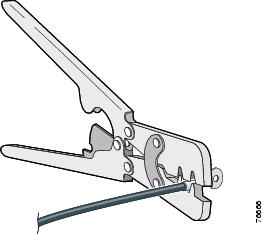 |
| Step 4 |
Slide the ground screw through the terminal. |
| Step 5 |
Insert the ground screw into the functional ground screw opening on the front panel. |
| Step 6 |
Attach the ring terminal to the chassis using the screw set aside in step 1. Use a ratcheting torque screwdriver to tighten the ground screws and ring terminal to the device front panel to 3.5 in-lb (0.4 N-m). See item (1 ) in the following figure.  |
| Step 7 |
Connect the other end of the ground wire to a known reliable earth ground point at your site. |
 Feedback