- Preface
- Overview
- Installing and Removing Power Components
- Installing and Removing Air Circulation Components
- Installing and Removing SFCs, RPs, MSCs, FPs, LSPs, PLIMs, and Associated Components
- Installing and Removing the Front Doors and Grille
- Cisco CRS 4-Slot Line Card Chassis System Specifications
- Index
Cisco CRS Carrier Routing System 4-Slot Line Card Chassis Installation Guide
Bias-Free Language
The documentation set for this product strives to use bias-free language. For the purposes of this documentation set, bias-free is defined as language that does not imply discrimination based on age, disability, gender, racial identity, ethnic identity, sexual orientation, socioeconomic status, and intersectionality. Exceptions may be present in the documentation due to language that is hardcoded in the user interfaces of the product software, language used based on RFP documentation, or language that is used by a referenced third-party product. Learn more about how Cisco is using Inclusive Language.
- Updated:
- July 20, 2011
Chapter: Installing and Removing Air Circulation Components
Installing and Removing Air Circulation Components
This chapter provides instructions on how to install and replace the Cisco CRS Carrier Routing System 4-Slot Line Card Chassis air circulation components.
This chapter presents the following topics:
•![]() About Line Card Chassis Airflow
About Line Card Chassis Airflow
•![]() How to Install or Remove Air Circulation Components
How to Install or Remove Air Circulation Components
About Line Card Chassis Airflow
The Cisco CRS 4-slot line card chassis has a single fan tray containing four fans that cool the chassis card cage. Cool air flows in at the bottom front of the chassis and flows through the chassis card cage and through the fans in the fan tray before being exhausted through the top rear of the chassis (see Figure 3-1).
In addition, each power module at the bottom of the chassis has self-contained fans that pull in cool air from the front of the chassis and exhaust warm air out the rear. There is parallel path for airflow through the fabric cards.
Figure 3-1 Airflow Through the Cisco CRS 4-Slot Line Card Chassis
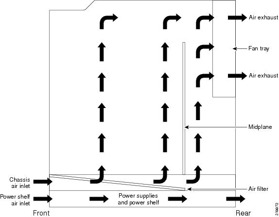
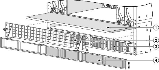
A replaceable air filter is located inside the chassis below the PLIM card cage at an angle. In addition, there is a removable air filter on the front of the power tray air intake grille on the front (PLIM) side of the chassis. (See Figure 3-2.)
Air Filter Replacement Frequency Recommendation
How often the air filters should be replaced depends on the facility environment. In a dirty environment, or when you start getting frequent temperature alarms, you should always check the intake grilles for debris, and then check the air filters to see if they need to be replaced.
Figure 3-2 System Air Filters
|
|
Chassis air filter |
|
Power tray and power supplies |
|
|
Air intake grille |
|
Power tray air filter |

Note ![]() We recommend that you check the air filters once a month. Replace a filter when you notice a significant amount of dust.
We recommend that you check the air filters once a month. Replace a filter when you notice a significant amount of dust.

The Cisco CRS 4-slot line card chassis airflow volumes are as follows:
•![]() Chassis airflow: Up to 880 cubic feet (24,919 liters) per minute
Chassis airflow: Up to 880 cubic feet (24,919 liters) per minute
•![]() Power system airflow: Up to 60 cubic feet (1699 liters) per minute
Power system airflow: Up to 60 cubic feet (1699 liters) per minute
How to Install or Remove Air Circulation Components
This section contains the following procedures:
•![]() Installing the Chassis Air Filter
Installing the Chassis Air Filter
•![]() Removing the Chassis Air Filter
Removing the Chassis Air Filter
•![]() Installing a Power Tray Air Filter
Installing a Power Tray Air Filter
•![]() Removing a Power Tray Air Filter
Removing a Power Tray Air Filter
Installing a Fan Tray
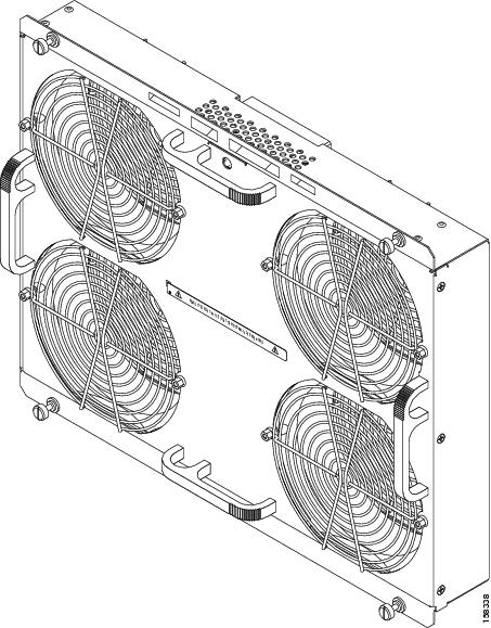
This section describes how to install a fan tray in the Cisco CRS 4-slot line card chassis. For information on the chassis airflow and circulation, see the "About Line Card Chassis Airflow" section. The fan tray installs into the rear (SFC) side of the chassis (see Figure 3-3). For complete information on regulatory compliance and safety, see Cisco CRS Carrier Routing System Regulatory Compliance and Safety Information.
Figure 3-3 Fan Tray
Prerequisites
No prerequisites exist for this task.
Required Tools and Equipment
You need the following tools and part to perform this task:
•![]() ESD-preventive wrist strap
ESD-preventive wrist strap
•![]() Large flat-blade screwdriver
Large flat-blade screwdriver
•![]() Fan tray (Cisco product number CRS-4-FAN-TR=)
Fan tray (Cisco product number CRS-4-FAN-TR=)
Steps
To install a fan tray, follow these steps:
Step 1 ![]() Attach the ESD-preventive wrist strap to your wrist and connect its leash to one of the ESD connection sockets on the rear (SFC) side of the chassis or a bare metal surface on the chassis.
Attach the ESD-preventive wrist strap to your wrist and connect its leash to one of the ESD connection sockets on the rear (SFC) side of the chassis or a bare metal surface on the chassis.
Step 2 ![]() Holding the fan tray by the handles, position it in front of the fan tray bay on the upper rear (SFC) side of the chassis. Slide the tray partway into its slot.
Holding the fan tray by the handles, position it in front of the fan tray bay on the upper rear (SFC) side of the chassis. Slide the tray partway into its slot.
Step 3 ![]() Slide the fan tray all the way in. Press it firmly into the chassis so that the connector on the back of the fan tray is seated firmly against the connector on the interior of the chassis.
Slide the fan tray all the way in. Press it firmly into the chassis so that the connector on the back of the fan tray is seated firmly against the connector on the interior of the chassis.
Step 4 ![]() Using the screwdriver, tighten the four captive screws (one for each corner).
Using the screwdriver, tighten the four captive screws (one for each corner).
Note ![]() All electrical and control line connections are made automatically when the connectors mate.
All electrical and control line connections are made automatically when the connectors mate.
Removing a Fan Tray
This section describes how to remove a fan tray from the Cisco CRS 4-slot line card chassis. For information on the chassis airflow and circulation, see the "About Line Card Chassis Airflow" section.
The fan tray installs into the rear (SFC) side of the chassis (see Figure 3-4). For complete information on regulatory compliance and safety, see Cisco CRS Carrier Routing System Regulatory Compliance and Safety Information.
Figure 3-4 Fan Tray
Prerequisites
No prerequisites exist for this task.
Required Tools and Equipment
You need the following tools to perform this task:
•![]() ESD-preventive wrist strap
ESD-preventive wrist strap
•![]() Large flat-blade screwdriver
Large flat-blade screwdriver
Steps
To remove a fan tray, follow these steps:
Step 1 ![]() Attach the ESD-preventive wrist strap to your wrist and connect its leash to one of the ESD connection sockets on the rear (SFC) side of the chassis or a bare metal surface on the chassis.
Attach the ESD-preventive wrist strap to your wrist and connect its leash to one of the ESD connection sockets on the rear (SFC) side of the chassis or a bare metal surface on the chassis.
Step 2 ![]() Using the large flat-blade screwdriver, loosen the four captive screws on the fan tray (one for each corner).
Using the large flat-blade screwdriver, loosen the four captive screws on the fan tray (one for each corner).
Step 3 ![]() Grasp the fan tray by the handles and pull it gently straight out to disconnect the fan tray from the connector mounted on the back of the fan tray.
Grasp the fan tray by the handles and pull it gently straight out to disconnect the fan tray from the connector mounted on the back of the fan tray.
Step 4 ![]() Remove the fan tray completely from the fan tray bay. Set the fan tray safely aside.
Remove the fan tray completely from the fan tray bay. Set the fan tray safely aside.
Installing the Chassis Air Filter
This section describes how to install the air filter in the Cisco CRS 4-slot line card chassis. For further information, see the "About Line Card Chassis Airflow" section. For complete information on regulatory compliance and safety, see Cisco CRS Carrier Routing System Regulatory Compliance and Safety Information.
The Cisco CRS 4-slot line card chassis has a serviceable air filter that plugs into the front (PLIM) side of the chassis (see item 1 in Figure 3-5) just inside the air intake slot. During operation, the air filter access is hidden by the lower chassis grille.
Figure 3-5 Chassis Air Filter
|
|
Chassis air filter |
|
Power tray and power supplies |
|
|
Air intake grille |
|
Power tray air filter |
Prerequisites
Before performing this task, you must first remove any chassis front cosmetic covers, the lower chassis air intake grille and power tray air filter cover (see the "Installing a Power Tray Air Filter" section).
Required Tools and Equipment
You need the following part to perform this task:
•![]() Chassis air filter (Cisco product number: CRS-4-FILTER=)
Chassis air filter (Cisco product number: CRS-4-FILTER=)
•![]() Medium flat-blade screwdriver
Medium flat-blade screwdriver
Steps
To install the chassis air filter, follow these steps:
Step 1 ![]() If an air filter is currently in the slot, remove it.
If an air filter is currently in the slot, remove it.
Step 2 ![]() Slide the new air filter into the air filter slot until it is seated fully within the slot.
Slide the new air filter into the air filter slot until it is seated fully within the slot.
Step 3 ![]() Replace the lower chassis grille:
Replace the lower chassis grille:
a. ![]() Position the grille in front of the air intake slot on the lower front side of the chassis and press it gently into place. Make sure that you align the guide pins on the lower corners of the grille with the guide pin holes on the chassis.
Position the grille in front of the air intake slot on the lower front side of the chassis and press it gently into place. Make sure that you align the guide pins on the lower corners of the grille with the guide pin holes on the chassis.
b. ![]() Use a medium flat-blade screwdriver to tighten the two captive screws (on for each side) that hold the grille to the front of the chassis.
Use a medium flat-blade screwdriver to tighten the two captive screws (on for each side) that hold the grille to the front of the chassis.
Removing the Chassis Air Filter
This section describes how to remove the air filter in the Cisco CRS 4-slot line card chassis. For further information, see the "About Line Card Chassis Airflow" section. For complete information on regulatory compliance and safety, see Cisco CRS Carrier Routing System Regulatory Compliance and Safety Information.
The chassis has a serviceable air filter that plugs into the front (PLIM) side of the chassis (see item 1 in Figure 3-6) just inside the air intake slot. During operation, the air filter access is hidden by the lower chassis grille.
Figure 3-6 Chassis Air Filter
|
|
Chassis air filter |
|
Power tray and power supplies |
|
|
Air intake grille |
|
Power tray air filter |
Prerequisites
Before performing this task, you must first remove the lower chassis grille and power tray air filter cover (see the "Installing a Power Tray Air Filter" section).
Required Tools and Equipment
You need the following tools to perform this task:
•![]() ESD-preventive wrist straps
ESD-preventive wrist straps
•![]() Large flat-blade screwdriver
Large flat-blade screwdriver
Steps
To remove the chassis air filter, follow these steps:
Step 1 ![]() Attach the ESD-preventive wrist strap to your wrist and connect its leash to one of the ESD connection sockets on the front (PLIM) side of the chassis or a bare metal surface on the chassis.
Attach the ESD-preventive wrist strap to your wrist and connect its leash to one of the ESD connection sockets on the front (PLIM) side of the chassis or a bare metal surface on the chassis.
Step 2 ![]() Unscrew the two captive screws that connect the air intake grille to the front (PLIM) side of the chassis.
Unscrew the two captive screws that connect the air intake grille to the front (PLIM) side of the chassis.
Step 3 ![]() Set the air intake grille carefully aside.
Set the air intake grille carefully aside.
Step 4 ![]() Grasp the air filter and carefully slide it from the slot. Set the air filter carefully aside.
Grasp the air filter and carefully slide it from the slot. Set the air filter carefully aside.
Step 5 ![]() Install the replacement air filter (if necessary). See the "Installing the Chassis Air Filter" section.
Install the replacement air filter (if necessary). See the "Installing the Chassis Air Filter" section.
What to Do Next
After performing this task, replace the lower chassis grille (see the "Installing a Power Tray Air Filter" section) and the front cover plates.
Installing a Power Tray Air Filter
This section describes how to install a power tray air filter for the Cisco CRS 4-slot line card chassis. For further information, see the "About Line Card Chassis Airflow" section. For complete information on regulatory compliance and safety, see Cisco CRS Carrier Routing System Regulatory Compliance and Safety Information.
The power tray has a serviceable air filter that is inserted into the lower chassis grille, just in front of the power tray (see item 4 in Figure 3-7).
Figure 3-7 Power Tray Air Filter
|
|
Chassis air filter |
|
Power tray and power modules |
|
|
Air intake grille |
|
Power tray air filter |
Prerequisites
No prerequisites exist for this task.
Required Tools and Equipment
You need the following tools and part to perform this task:
•![]() ESD-preventive wrist strap
ESD-preventive wrist strap
•![]() Medium flat-blade screwdriver
Medium flat-blade screwdriver
•![]() Power tray air filter
Power tray air filter
Steps
To install a power tray air filter, follow these steps:
Step 1 ![]() Attach the ESD-preventive wrist strap to your wrist and connect its leash to one of the ESD connection sockets on the front (PLIM) side of the chassis or a bare metal surface on the chassis.
Attach the ESD-preventive wrist strap to your wrist and connect its leash to one of the ESD connection sockets on the front (PLIM) side of the chassis or a bare metal surface on the chassis.
Step 2 ![]() Remove the lower chassis grille:
Remove the lower chassis grille:
•![]() Use the medium flat-blade screwdriver to loosen the two captive screws (one for each side) that hold the grille to the front of the chassis.
Use the medium flat-blade screwdriver to loosen the two captive screws (one for each side) that hold the grille to the front of the chassis.
•![]() Gently remove the grille from the chassis.
Gently remove the grille from the chassis.
Step 3 ![]() Slide the air filter into the air filter slot on the grille (see Figure 3-7).
Slide the air filter into the air filter slot on the grille (see Figure 3-7).
Step 4 ![]() Reinstall the lower chassis grille:
Reinstall the lower chassis grille:
a. ![]() Position the grille in front of the air intake slot on the lower front side of the chassis and press it gently into place. Make sure that you align the guide pins on the lower corners of the grille with the guide pin holes on the chassis.
Position the grille in front of the air intake slot on the lower front side of the chassis and press it gently into place. Make sure that you align the guide pins on the lower corners of the grille with the guide pin holes on the chassis.
b. ![]() Use a medium flat-blade screwdriver to tighten the two captive screws (on for each side) that hold the grille to the front of the chassis.
Use a medium flat-blade screwdriver to tighten the two captive screws (on for each side) that hold the grille to the front of the chassis.
Removing a Power Tray Air Filter
This section describes how to remove a power tray air filter. For further information, see the "About Line Card Chassis Airflow" section. For complete information on regulatory compliance and safety, see Regulatory Compliance and Safety Information for the Cisco CRS Carrier Routing System.
The power tray has a serviceable air filter that is inserted into the lower chassis grille, just in front of the power tray (see item 4 in Figure 3-8).
Figure 3-8 Power Tray Air Filter
|
|
Chassis air filter |
|
Power tray and power modules |
|
|
Air intake grille |
|
Power tray air filter |
Prerequisites
No prerequisites exist for this task.
Required Tools and Equipment
You need the following tools to perform this task:
•![]() ESD-preventive wrist strap
ESD-preventive wrist strap
•![]() Medium flat-blade screwdriver
Medium flat-blade screwdriver
Steps
To remove a power tray air filter, follow these steps:
Step 1 ![]() Attach the ESD-preventive wrist strap to your wrist and connect its leash to one of the ESD connection sockets on the front (PLIM) side of the chassis or a bare metal surface on the chassis.
Attach the ESD-preventive wrist strap to your wrist and connect its leash to one of the ESD connection sockets on the front (PLIM) side of the chassis or a bare metal surface on the chassis.
Step 2 ![]() Remove the lower chassis grille (if necessary):
Remove the lower chassis grille (if necessary):
a. ![]() Use a medium flat-blade screwdriver to tighten the two captive screws (one for each side) that hold the grille to the front of the chassis.
Use a medium flat-blade screwdriver to tighten the two captive screws (one for each side) that hold the grille to the front of the chassis.
b. ![]() Gently remove the grille from the chassis.
Gently remove the grille from the chassis.
Step 3 ![]() Slide the air filter from the air filter slot on the grille (see Figure 3-8).
Slide the air filter from the air filter slot on the grille (see Figure 3-8).
What to Do Next
After performing this task, you may install a new air filter (see the "Installing a Power Tray Air Filter" section).
 Feedback