Cisco Connected Grid Device Manager Installation and User Guide, Release 3.1
Bias-Free Language
The documentation set for this product strives to use bias-free language. For the purposes of this documentation set, bias-free is defined as language that does not imply discrimination based on age, disability, gender, racial identity, ethnic identity, sexual orientation, socioeconomic status, and intersectionality. Exceptions may be present in the documentation due to language that is hardcoded in the user interfaces of the product software, language used based on RFP documentation, or language that is used by a referenced third-party product. Learn more about how Cisco is using Inclusive Language.
- Updated:
- June 13, 2013
Chapter: Using the Device Manager
- Overview
- How to Use the Device Manager
- Connect to the CGR 1000
- Setting Operating Mode
- Accessing Work Authorizations
- Performing Tasks on the Router
- Import Certificates
- Disconnect from the CGR 1000
- Connection Override
- Example Log File Output
- Feature History
Using the Device Manager
The chapter explains how to use the Device Manager and contains the following sections:
Overview
Device Manager displays the At a Glance page after securely connecting to the CGR 1000. From this page, you can perform the following tasks as determined by your assigned role. (See Role-based Access Control.)
- Test Connectivity: Verify access to a device (IP address) from the CGR 1000 by using ping to check link connectivity and quality, and initiate a traceroute for an inaccessible IP address. (See Test Connectivity.)
- Manage Interfaces: Bring up or shut down an CGR 1000 interface, view details for an interface, and reload a module. (See Manage Interfaces.)
- Change Configuration: Update the CGR 1000 configuration with a provided configuration file, and then reboot the router with the new configuration. (See Change Configuration.)
- Update Image: Upload a copy of a software image onto the CGR 1000 for immediate installation or for a deferred update of the image. ( See Update Image.)
- Retrieve Report: Download and view the CGR 1000 system logs. (See Retrieve Report.)
- Manage Modules: Add and Remove Modules from the CGR 1000 by employing a wizard that guides you through the process. (See Manage Modules.)
- Advanced Command: Provides a console-like interface to troubleshoot the CGR 1000 by using CLI commands. Supported queries include verifying the system time, viewing the current router configuration, saving the current configuration, viewing the current file directory, rebooting the router, or saving the window output to a file. (See Advanced Command.)
Figure 3-1 At a Glance Page for the CGR 1240
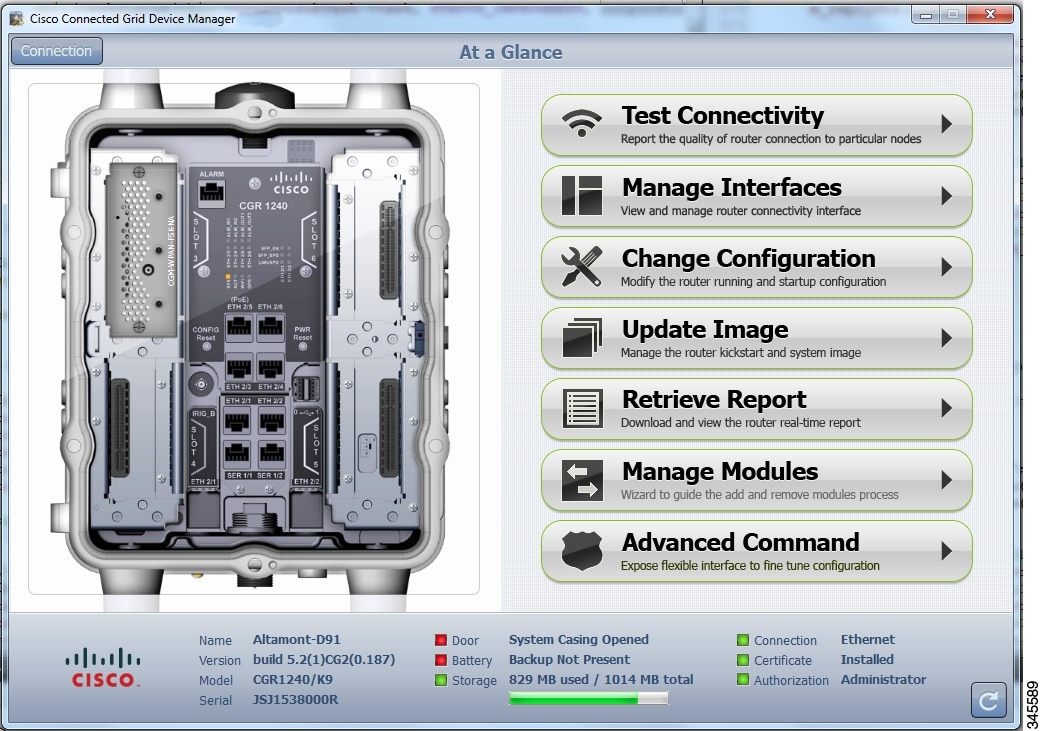
The CGR 1000 image that appears on the left side of the At a Glance page provides a view of the CGR 1000 router to which the Device Manager connects. The CGR 1000 image also displays the Connected Grid Modules installed, as well as LEDs that indicate if the modules are operating. You can also view interfaces, available module slots, and other information. The information can be refreshed at any time by clicking the Refresh icon, located on the bottom right-hand corner of the page.
How to Use the Device Manager
Following are a few examples of how to use the Device Manager:
- Devices connected to a CGR 1000 cannot be reached. Start the Device Manager, connect to the router, and then check connectivity to the device. (See Test Connectivity.)
–![]() When you reconnect to the devices, review the CGR 1000 configuration information.
When you reconnect to the devices, review the CGR 1000 configuration information.
(See Advanced Command.)
–![]() When the configuration information is incorrect, you can update the configuration (see
When the configuration information is incorrect, you can update the configuration (see
Update Configuration) by adding a configuration file to the Device Manager and then updating the CGR 1000 configuration. After you update the configuration (see Advanced Command) the router automatically resets and restarts with the new configuration.
- A software image update must be uploaded and installed on the CGR 1000. Start the Device Manager, upload the new image file, and then update the router with the new image. The router automatically restarts after you update the software image. (See Update Image.)
- Newly deployed CGR 1000s do not appear in the back-end system. Start the Device Manager and review the router graphic on the At a Glance page. Check the installed modules and their LEDs to verify their operation. When the LEDs are not flashing, check the installation status of the modules. Refer to the configuration guide for the module. (See www.cisco.com/go/cgr1000-docs.)
- (CGR 1240 Only) The door of the CGR 1240 is open. Start the Device Manager and check the status of the door (bottom of the At a Glance page). When the door status indicates a status of System Casing Open, you must physically access the CGR 1240 to verify the status of the door. After closing the door, click the Refresh icon (bottom right) on the Device Manager and verify that the door status displays System Casing Closed.
- A WiMAX module is being added to a CGR 1240. Start the Device Manager and navigate to the
At a Glance > Manage Module page. (See Manage Modules.) - When there are issues related to WiMAX connectivity, (for instance, after a storm, the WiMAX antenna may not be pointing in the right direction, which can cause RSSI/CINR values to drop), you can use the information on the WiMAX Module Activity page to help troubleshoot the issue. If the issue involves a directional antenna, you can change the direction of the antenna and watch RSSI/CINR values change accordingly. (See View Details for an Interface.)
- A WiMAX module needs to be reloaded in the event of a hardware failure, hang or crash. (See Reload a Module.)
Connect to the CGR 1000
You can connect to a CGR 1000 by either Ethernet or WiFi. WiFi connectivity ensures data traffic between the Device Manager and the router are protected by WPA Layer 2 security, once the association and key handshake are complete. The Ethernet connection is secured by HTTPS only.
Connect to the Device Manager by employing one of the following methods:
- Auto Discovered IPv6 address (preferred method for the field)
- IPv4 address (such as 128.128.128.128)
- IPv6 address (such as fe80::d81f:6402:2ae4:4ea8)
Follow these steps to start the Device Manager:
Step 1![]() After installing the Device Manager on your laptop, double-click on the Cisco CGD Manager icon on your Desktop, or select Start > All Programs > Cisco CGD Manager.
After installing the Device Manager on your laptop, double-click on the Cisco CGD Manager icon on your Desktop, or select Start > All Programs > Cisco CGD Manager.
The application opens the Connect to the Router page.

Step 2![]() On the Connect to the Router page, select the connection method: Ethernet, WiFi, Auto Detect.
On the Connect to the Router page, select the connection method: Ethernet, WiFi, Auto Detect.
- (WiFi only) Enter the SSID and Passphrase.
- Enter the router IP address, or select the checkbox to auto-discover the IP address.

Note![]() To Auto Discover an IPv6 address, the laptop running Device Manager must be directly connected to the CGR 1000 via Ethernet or WiFi. By design, the Auto Discover function works when there is only one active router within the same network.
To Auto Discover an IPv6 address, the laptop running Device Manager must be directly connected to the CGR 1000 via Ethernet or WiFi. By design, the Auto Discover function works when there is only one active router within the same network.
Step 3![]() On the Connect to the Router page, do one of the following:
On the Connect to the Router page, do one of the following:
- To set or modify the operating mode (non-NMS or NMS mode) of the Device Manager, click the Settings icon on the bottom-right of the Router page. Non-NMS is the default setting.
The Setup Wizard appears. Proceed to Setting Operating Mode.
- To connect to the router to query the router details (after you set the operating mode), click either Connect (non-NMS mode) or Connect to the Router (NMS mode).
The At a Glance page appears. Proceed to Performing Tasks on the Router.

Tip![]() If you have problems connecting to the Device Manager, refer to Chapter 4, “Troubleshooting” for troubleshooting suggestions.
If you have problems connecting to the Device Manager, refer to Chapter 4, “Troubleshooting” for troubleshooting suggestions.
Setting Operating Mode
The operating mode of the Device Manager determines what tasks you can access and view from the Device Manager and how it interacts with systems within the Connected Grid network field deployment. (See Performing Tasks on the Router.)
You can configure the Device Manager to operate in one of the following modes:
NMS Mode –When you have a CG-NMS operating in the network, you can connect to that system with the Device Manager to download and update work authorizations. Work authorizations allow the Device Manager to view status and perform tasks on the CGR 1000. To operate in conjunction with a CG-NMS system, configure the Device Manager to operate in NMS-mode.
Non-NMS Mode– When you do not have a CG-NMS operating in the network or do not want to connect to that system, configure the Device Manager to operate in non-NMS mode. In this case, you connect directly to a CGR 1000 by either WiFi (with valid SSID and passphrase) or Ethernet to view status and perform tasks on the CGR 1000.
Follow these steps to configure the Device Manager operating mode:
Step 1![]() On the Setup Wizard page, select one of the following options:
On the Setup Wizard page, select one of the following options:
- To have the Device Manager connect to the Router only (non-NMS mode), select the No radio button, and then click Next. Proceed to Step 2.
- To have the Device Manager operate in conjunction with a CG-NMS system (NMS mode), select the Yes radio button, and then click Next. Proceed to Step 3.

Step 2![]() (Non-NMS mode) On the Certificate Configuration page, review the Common Name and the certificate details for accuracy and do the following:
(Non-NMS mode) On the Certificate Configuration page, review the Common Name and the certificate details for accuracy and do the following:
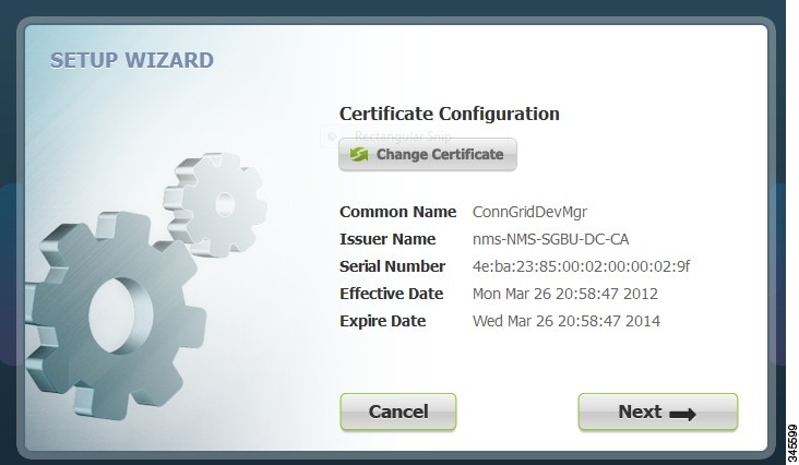
- To accept the current certificate, click Next. Proceed to b.
- To select a different certificate, click Change Certificate. Proceed to Import Certificates.
- To exit the Setup Wizard, click Cancel.
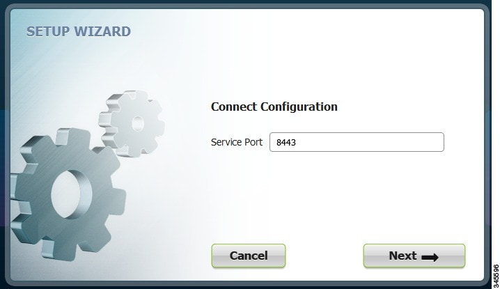
a.![]() On the Connect Configuration page, confirm the Service Port and click Next.
On the Connect Configuration page, confirm the Service Port and click Next.
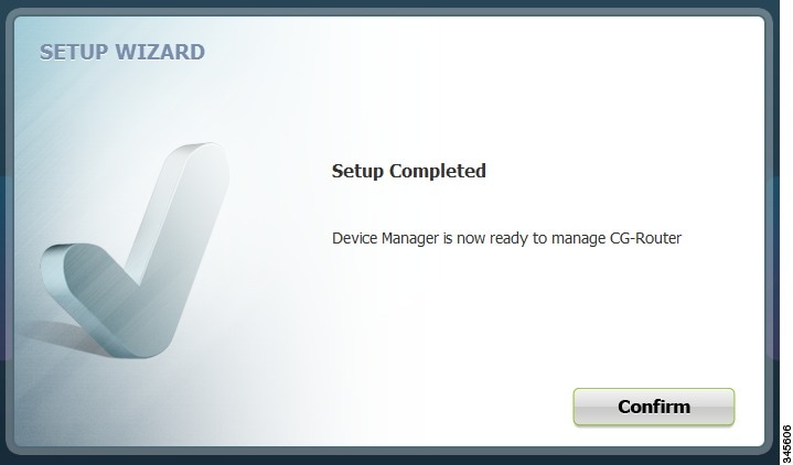
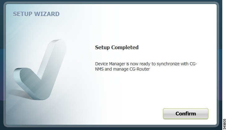
b.![]() On the Setup Completed page, click Confirm.
On the Setup Completed page, click Confirm.
c.![]() On the Connect to the Router page that appears, click Connect.
On the Connect to the Router page that appears, click Connect.
The At a Glance page appears. Proceed to Performing Tasks on the Router.
Step 3![]() (CG-NMS mode) On the NMS Configuration page, do the following:
(CG-NMS mode) On the NMS Configuration page, do the following:
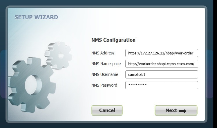
a.![]() Enter the NMS address (IP address), NMS Namespace, NMS Username and NMS Password for the CG-NMS application server, and then click Next.
Enter the NMS address (IP address), NMS Namespace, NMS Username and NMS Password for the CG-NMS application server, and then click Next.
b.![]() On the Certificate Configuration page, review the certificate details, and do one of the following:
On the Certificate Configuration page, review the certificate details, and do one of the following:
–![]() To accept the current certificate, click Next. Proceed to c.
To accept the current certificate, click Next. Proceed to c.
–![]() To select a different certificate, click Change Certificate. Proceed to Import Certificates.
To select a different certificate, click Change Certificate. Proceed to Import Certificates.
–![]() To exit the Setup Wizard, click Cancel.
To exit the Setup Wizard, click Cancel.
c.![]() On the Connect Configuration page, confirm the Service Port and click Next.
On the Connect Configuration page, confirm the Service Port and click Next.
d.![]() On the Setup Completed page, click Confirm.
On the Setup Completed page, click Confirm.
e.![]() On the Work Authorization page that appears, click Confirm. Proceed to Accessing Work Authorizations.
On the Work Authorization page that appears, click Confirm. Proceed to Accessing Work Authorizations.
Accessing Work Authorizations
The Device Manager must be operating in the NMS mode for you to view and download work orders from the CG-NMS to the Work Authorization page. (See Setting Operating Mode.)
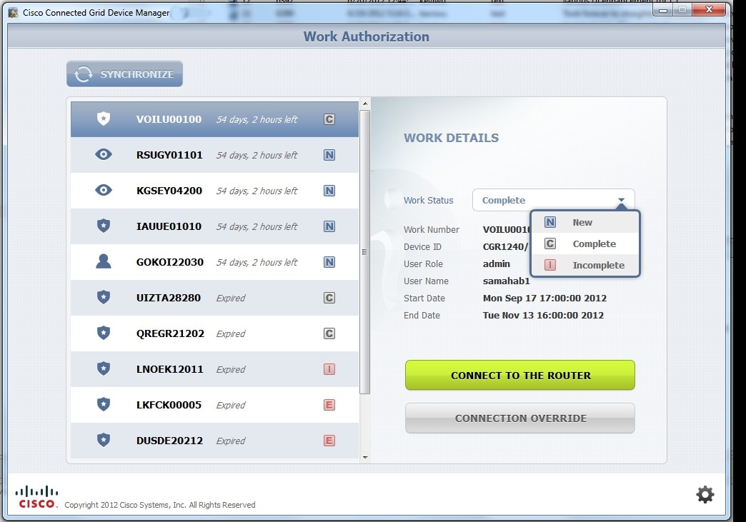
The Work Authorization page is the opening page of the Device Manager when operating in NMS mode.
Whenever work or direct inspection of a CGR 1000 is necessary by a field technician, an admin generates a work order on the CG-NMS. Work orders include encrypted WiFi credentials necessary for the technician to connect to the router. In most cases, a work order requires a user with an assigned user role of technician (tech) to access and update the work order. However, a user with a viewer role can retrieve status on a CGR 1000 but not perform tasks on the router.
Each work order has an expected start and end date, which is noted in the Work Details summary (right pane) along with user role and user name and the current state of the work order: New (N), Complete (C), Incomplete (I), or Expired (E).
This section covers the following topics:
- Enabling Feature on Router
- Downloading Work Authorizations
- Viewing Work Details
- Updating Work Details
Tip![]() To perform additional tasks on the router, click Connect to the Router on the Work Authorization page to launch the At a Glance page. (See Performing Tasks on the Router.)
To perform additional tasks on the router, click Connect to the Router on the Work Authorization page to launch the At a Glance page. (See Performing Tasks on the Router.)
Enabling Feature on Router
The following commands must be entered on the CGR 1000 to support communication between the Device Manager and the router when Work Authorization is in use:
Downloading Work Authorizations
To download the latest work orders from CG-NMS and upload new status of the work orders to CG-NMS, click Synchronize on the Work Authorization page.
Viewing Work Details
The Work Number in the Work Details section (right pane) corresponds to an existing work order within a Utility management or operations system that the technician can access to get additional details on the work order.
Generally, a technician synchronizes with the CG-NMS at the beginning of the day to download work orders before heading to the field and then again at the end of the day when back at the office to update CG-NMS with the changes.
To view work order details, do the following:
Step 1![]() On the Work Authorization page, click a work order (left pane).
On the Work Authorization page, click a work order (left pane).
Step 2![]() Using the Work Number that appears (left pane), locate the specific work details from the appropriate system and then do one of the following:
Using the Work Number that appears (left pane), locate the specific work details from the appropriate system and then do one of the following:
- When you complete the work order, select Complete from the Work Status drop-down menu.
- When you are not able to complete the work order, select Incomplete from the Work Status drop-down menu.
The work order (left pane) reflects the status change.
Step 3![]() When connected to CG-NMS, click Synchronize to update the CG-NMS.
When connected to CG-NMS, click Synchronize to update the CG-NMS.
After synchronization with the CG-NMS, all Completed, Incomplete, and Expired work orders are removed from the Device Manager display.
Updating Work Details
A work order has four possible states: New (N), Complete (C), Incomplete (I), or Expired (E).
To update the status of a work order, do the following:
Step 1![]() On the Work Authorization page, select the Work Status drop-down menu (right pane).
On the Work Authorization page, select the Work Status drop-down menu (right pane).
Step 2![]() Select the current state of the work order.
Select the current state of the work order.
The Work Authorization page reflects the new state of the work order (left pane).
Step 3![]() To update the CG-NMS database with this change, click Synchronize.
To update the CG-NMS database with this change, click Synchronize.
Performing Tasks on the Router
The At a Glance page appears after you click Connect from the Connect to the Router page (Non-NMS mode) or click Connect to the Router from the Work Authorization page (NMS mode).
Listed below are all the possible tasks that a user can perform. However, your assigned role determines which tasks you can access. The Device Manager displays or restricts tasks based on your assigned role (or roles). The above At a Glance view represents an Admin role. (See Role-based Access Control.)
- Troubleshoot connectivity between a CGR 1000 and the devices connected to the router.
(See Test Connectivity.) - Bring up or shut down a CGR 1000 interface. (See Manage Interfaces.)
- Check and update the current CGR 1000 configuration.
(See Change Configuration and Advanced Command.)
- Upload and/or update the CGR 1000 image and reset the router. (See Update Image.)
- View real-time CGR 1000 configuration log for troubleshooting. (See Retrieve Report.)
- Add and Remove Modules from the CGR 1000 by employing a wizard that guides you through the process. (See Manage Modules.)
- View module activity and reload a module (See View Details for an Interface and Reload a Module.)
- Use advanced commands to troubleshoot the CGR 1000. (See Advanced Command.)
Test Connectivity
The Test Connectivity task allows you to confirm connectivity to a device from the CGR 1000.
Tip![]() Before you can check a device connection or route to a CGR 1000, you must add the IPv4 or IPv6 address of the device to the Device Manager.
Before you can check a device connection or route to a CGR 1000, you must add the IPv4 or IPv6 address of the device to the Device Manager.

Add a Device IP Address
Follow these steps to add a device IP address:
Step 1![]() From the At a Glance page, click Test Connectivity.
From the At a Glance page, click Test Connectivity.
The Test Connectivity page displays the defined sample devices and/or target addresses.
Step 2![]() Click Add to create a target IP address.
Click Add to create a target IP address.

Step 3![]() In the Target Description field, enter a description for the device.
In the Target Description field, enter a description for the device.
Step 4![]() In the Target IP Address field, enter the IP address (IPv4 or IPv6) of the device.
In the Target IP Address field, enter the IP address (IPv4 or IPv6) of the device.
You can now test the connectivity to the device you just added to the Device Manager.
Ping a Device IP Address
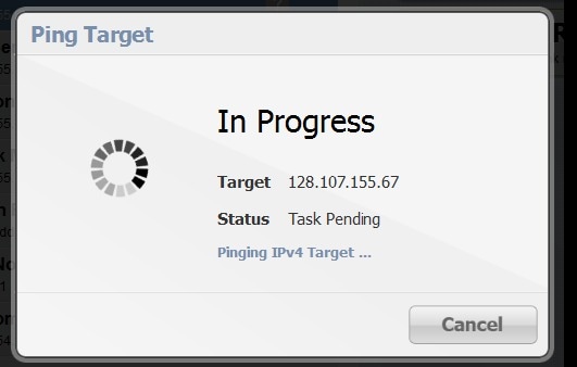
The Ping feature allows you to verify connectivity to a device by querying the target IP address.
Follow these steps to test connectivity between the CGR 1000 and the device:
Step 1![]() On the Test Connectivity page, click on a target IP address from the listing on the page (left pane).
On the Test Connectivity page, click on a target IP address from the listing on the page (left pane).
The In Progress dialog box appears.
When the system successfully pings the device, the Target Reached dialog box appears.
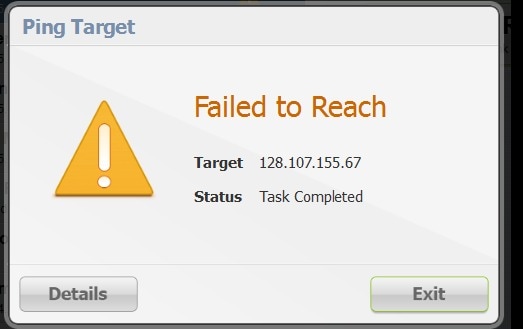
If the system does not successfully ping a device, refer to Failed Ping.
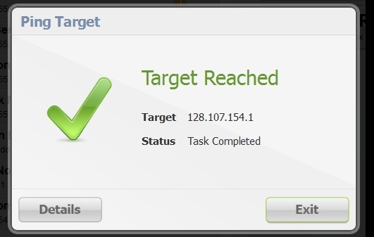
Step 3![]() Click Details to view details or click Exit to close the window.
Click Details to view details or click Exit to close the window.
Failed Ping
Follow these steps if the ping of the target IP address is unsuccessful:
Step 1![]() In the Failed to Reach dialog box, click Details to view the reason the system could not reach the IP address.
In the Failed to Reach dialog box, click Details to view the reason the system could not reach the IP address.
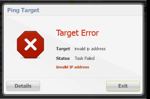
Step 2![]() In the Target Error dialog box, click Exit after reviewing the reason for the error.
In the Target Error dialog box, click Exit after reviewing the reason for the error.
Proceed to Trace Route a Device IP Address.
Trace Route a Device IP Address
When an IP address cannot be reached using Ping, you can use the Trace Route feature to check the route taken to reach the device IP address.
Follow these steps to trace the route of the IP address:
Step 1![]() On the Test Connectivity page, select the device IP address from the list.
On the Test Connectivity page, select the device IP address from the list.
- If the trace route is successful, click Exit in the Trace Route dialog box.
- If the trace route is unsuccessful, proceed to Remove a Device IP Address.
Remove a Device IP Address
After you have tested a target IP address and verified its connectivity, you can remove the device entry from the Device Manager. You can also remove an IP address that the application identifies as incorrect during failed pings and trace route attempts.
Follow these steps to remove a target IP address:
Step 1![]() On the Test Connectivity page, select the target IP address from the list.
On the Test Connectivity page, select the target IP address from the list.
Manage Interfaces
You can bring up or shut down an interface on the Manage Interfaces page. You can also view details about a module’s activity and reload a module from the Manage Interfaces page.
- When an interface is up (appears as green), the line protocol is currently active. When an interface is down (appears as red), it means the line protocol is not active.
- When an interface is administratively down (appears as gray), the line interface was taken down by the administrator.
All interfaces installed within the CGR 1000 display automatically.

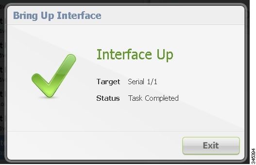
Bring Up an Interface
When an interface is shut down for any reason, you can attempt to bring up the interface by doing the following:
Step 1![]() From the At a Glance page, click Manage Interfaces.
From the At a Glance page, click Manage Interfaces.
Step 2![]() On the Manage Interfaces page, select an interface and then click Bring Up Interface.
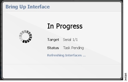
On the Manage Interfaces page, select an interface and then click Bring Up Interface.
The In Progress message appears. When the interface is up, the Interface Up dialog box appears.
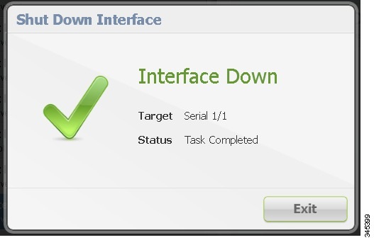
Shut Down an Interface

Follow these steps to shut down an interface:
Step 1![]() From the At a Glance page, click Manage Interfaces.
From the At a Glance page, click Manage Interfaces.
Step 2![]() On the Manage Interfaces page, select an interface and then click Shut Down.
On the Manage Interfaces page, select an interface and then click Shut Down.
The In Progress message appears. When the process completes, the Interface Down dialog box appears.

View Details for an Interface
The View Details feature allows you to display information for the selected interface and related module, including interface status, model number, MAC and IP addresses, and dynamic statistics. The information is updated every 10 seconds.
Note![]() In this release, details are available for the WiMAX module only.
In this release, details are available for the WiMAX module only.
Follow these steps to view details for a module:
Step 1![]() From the At a Glance page, click Manage Interfaces.
From the At a Glance page, click Manage Interfaces.
Step 2![]() On the Manage Interfaces page, select an interface and then click View Details.
On the Manage Interfaces page, select an interface and then click View Details.
The Module Activity page appears.

WiMAX Details
The following information is displayed for the WiMAX module:
- Slot in which module is inserted
- Model number
- MAC address
- IP address
- Physical layer state (indicates Connected, Disconnected, Scanning, or Authenticating)
- BSID (ID of the base station to which the WiMAX module is connected)
- Frequency of transmission of the WiMAX module
- Channel bandwidth (bandwidth supported by the WiMAX module)
- RSSI (Received Signal Strength Indication measured in dBm)
- CINR (Carrier to Interference Noise Ratio measured in dB. A higher value indicates better signal strength)
- Packets in (number of incoming packets)
- Packets out (number of outgoing packets)
- DL Bad CRC Packets (number of bad packets during download - ideally 0)
- Hardware version
- Board version
Reload a Module
Reloading a module shuts off power to the module then powers it on again.
Note![]() In this release, the Reload Module feature is available for the WiMAX module only.
In this release, the Reload Module feature is available for the WiMAX module only.
Follow these steps to reload a module:
Step 1![]() From the At a Glance page, click Manage Interfaces.
From the At a Glance page, click Manage Interfaces.
Step 2![]() On the Manage Interfaces page, select an interface and then click View Details.
On the Manage Interfaces page, select an interface and then click View Details.
The Module Activity page appears.
The message Reloading module... appears in the Updates area (bottom of left pane). When reloading is complete, the message Module reloaded successfully appears in the Updates area, and it takes 3-4 minutes for WiMAX module base station connectivity to be reestablished.
Change Configuration
The Change Configuration task allows you to upload a configuration file to the Device Manager and then use that file to update the configuration of the CGR 1000. The configuration file information must include version, username and password, Ethernet and WiFi interfaces, and Device Manager (CGDM) and IP HTTPS configurations.
Note![]() The configuration file must be a complete and valid CGR 1000 configuration. When the configuration file contains missing fields, the Device Manager stops the file upload and warns that the configuration file is incomplete. When you receive an error while updating the configuration file, check the configuration file for missing information.
The configuration file must be a complete and valid CGR 1000 configuration. When the configuration file contains missing fields, the Device Manager stops the file upload and warns that the configuration file is incomplete. When you receive an error while updating the configuration file, check the configuration file for missing information.
Add a Configuration File
Follow these steps to add a configuration file to the Device Manager:
Step 1![]() From the At a Glance page, click Change Configuration.
From the At a Glance page, click Change Configuration.
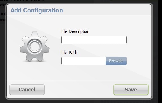
Step 3![]() In the Add Configuration dialog box:
In the Add Configuration dialog box:
a.![]() Enter a file description for the configuration file that you are going to upload.
Enter a file description for the configuration file that you are going to upload.
b.![]() Click Browse to navigate to the configuration file location and select the file.
Click Browse to navigate to the configuration file location and select the file.
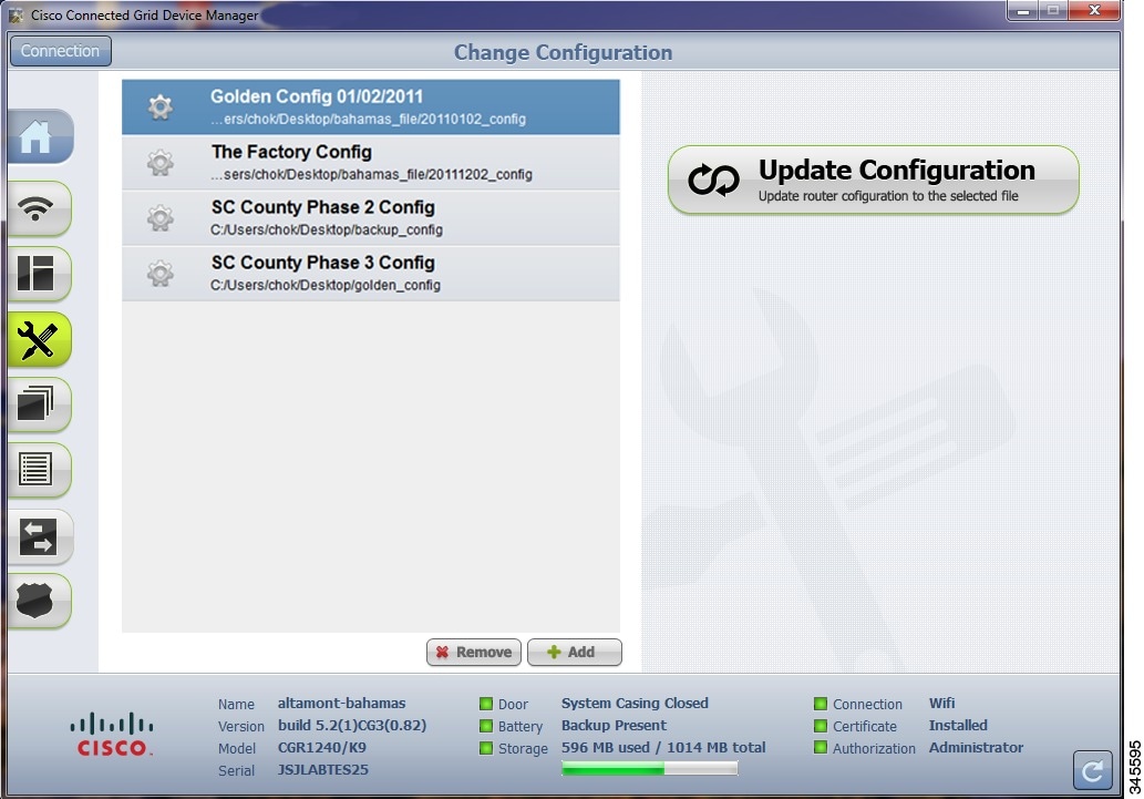
Update Configuration
After uploading the configuration file to Device Manager, you can use the file to update the CGR 1000 configuration.
Follow these steps to update the configuration file on the CGR 1000:
Step 1![]() On the Change Configuration page, select the desired configuration file (left pane).
On the Change Configuration page, select the desired configuration file (left pane).
Step 2![]() Click Update Configuration.
Click Update Configuration.
- If a confirmation dialog box appears, click Confirm to verify that you would like to change the router configuration.
- If an error message appears, the file did not upload to the CGR 1000.
Proceed to Correct a Configuration File.
Correct a Configuration File
A configuration file upload fails because the configuration file has missing fields such as version, username and password, Ethernet and WiFi interfaces, and Device Manager (CGDM) and IP HTTPS details.
To correct a configuration file error:
Step 1![]() Check the configuration file for errors. If errors or missing information exist, make corrections.
Check the configuration file for errors. If errors or missing information exist, make corrections.
Step 2![]() Remove the current configuration file from the Device Manager. (See Remove Configuration File.)
Remove the current configuration file from the Device Manager. (See Remove Configuration File.)
Step 3![]() Add the updated configuration file to Device Manager. (See Add a Configuration File.)
Add the updated configuration file to Device Manager. (See Add a Configuration File.)
Step 4![]() Update the configuration file. (See Update Configuration.)
Update the configuration file. (See Update Configuration.)
Remove Configuration File
After you update the CGR 1000 with the new configuration file, you can remove the file from Device Manager. You can also use this function to remove unwanted or duplicate configuration files.
Follow these steps to remove a configuration file:
Step 1![]() On the Change Configuration page, select the configuration file you want to remove from the list.
On the Change Configuration page, select the configuration file you want to remove from the list.
Update Image
The CGR 1000 image bundle contains information that the router uses when starting up and operating. The information in the image contains information on FPGA, 3G, wireless drivers, and so on. The only acceptable file format for the Cisco CGR 1000 image file is a zip bundle, which contains a manifest file with information on versioning and files. Any missing files in the zip bundle cancels the update. You can find the official Cisco CGR 1000 zip bundle on Cisco.com.
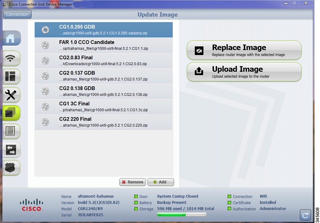
Upload Image
Before you can update an image on the CGR 1000, you must upload the image to the Device Manager.
The Upload Image option allows you to upload and store a copy of a software image on the CGR 1000 without initiating an immediate image install. This capability allows operations personnel to use CG-NMS or a Utility management tool to install and reboot the CGR 1000 when network conditions allow.
Follow these steps to upload a image:
Step 1![]() From the At a Glance page, click Update Image.
From the At a Glance page, click Update Image.
Step 2![]() On the Update Image page, select the CGR 1000 software image that you want to upload.
On the Update Image page, select the CGR 1000 software image that you want to upload.
Note![]() If the software image that you want to install on the CGR 1000 is not listed, click Add and browse to the image, and then click OK to upload the image.
If the software image that you want to install on the CGR 1000 is not listed, click Add and browse to the image, and then click OK to upload the image.
The new image is stored on the CGR 1000 router until you are ready to replace the image on the router. (See Replace Image.)
Replace Image
Follow these steps to replace an image:
Step 1![]() On the Update Image page, select an CGR 1000 image.
On the Update Image page, select an CGR 1000 image.
A confirmation dialog box appears.
Step 3![]() To begin the replace image process, click Confirm.
To begin the replace image process, click Confirm.
Step 4![]() After the router software update completes, the router restarts.
After the router software update completes, the router restarts.
Remove Image
After you update an image, you can remove the image file from the Device Manager. You can also use the Remove image option to remove a image file you added mistakenly.
Follow these steps to remove an image:
Step 1![]() On the Update Image page, select an CGR 1000 image.
On the Update Image page, select an CGR 1000 image.
Step 2![]() Click the Remove button (bottom of page).
Click the Remove button (bottom of page).
Retrieve Report
You can retrieve real-time reports of log events from the CGR 1000 and view them on the Retrieve Report page or save the information to a .txt file.
- You can specify that you want to retrieve and view all CGR 1000 log events (Retrieve All) or view a specified number of log events (200 or 1000)
- You can specify that you want to save a copy of the log events that display on the Retrieve Report page to your laptop (Save Report)
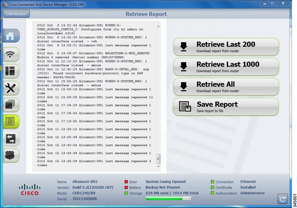
Retrieve and Save Reports
Follow these steps to retrieve real-time reports from the CGR 1000:
Step 1![]() From the At a Glance page, click Retrieve Report.
From the At a Glance page, click Retrieve Report.
Step 2![]() On the Retrieve Report page, click the type of report that you want to view or save:
On the Retrieve Report page, click the type of report that you want to view or save:
- Retrieve Last 200–Displays the last 200 log events of the CGR 1000.
- Retrieve Last 1000–Displays the last 1000 log events of the CGR 1000.
- Retrieve All–Displays all current log events of the CGR 1000.
- Save Report–Saves a copy of the retrieved log events (displayed on the page) to a default file, systemlog.txt. By default, the application saves this file in the Documents folder. However, you can specify the destination for the file. See SYSTEMLOG.TXT SAMPLE for example output.
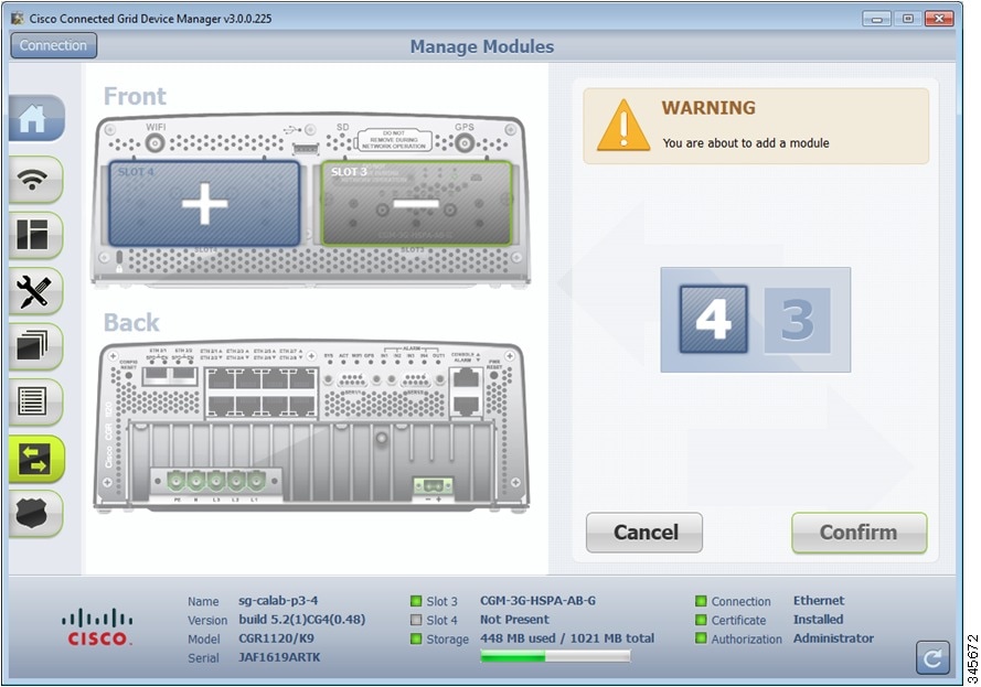
Manage Modules
The Manage Modules page provides a wizard that guides you through the process of adding or removing 3G and WiMAX modules.
The Device Manager updates the configuration file and reloads the CGR 1000 after you add or remove a module.
The plus sign (+) indicates an available slot.
The minus sign (-) indicates an occupied slot.
This section covers the following topics:
Tip • For details on opening the chassis door of the CGR 1240, please refer to the “Opening the Router Chassis” chapter in the Cisco 1240 Connected Grid Router Hardware Installation Guide at:
www.cisco.com/go/cgr1000-docs
- For details on installing a specific module, refer to the Installation and Configuration Guide for that module at: www.cisco.com/go/cgr1000-docs
Add a Module
Note![]() You cannot run any other operations when adding the module.
You cannot run any other operations when adding the module.
To add a module, do the following:
Step 1![]() On the Manage Modules page, click on a plus (+) sign in the router diagram (left pane) to get started.
On the Manage Modules page, click on a plus (+) sign in the router diagram (left pane) to get started.
A blue outline appears around the slot in the router diagram to confirm selection, and a Please wait... message appears on the page. Do not install the module until this message disappears from the page.
Step 2![]() After the Please wait... message disappears, insert the module into the physical slot of the router.
After the Please wait... message disappears, insert the module into the physical slot of the router.
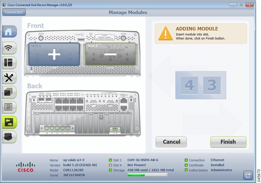
The following message appears on the page to indicate an update to the configuration file is in process:
Inserting module into slot. This process will take several minutes. Please wait.
A green line appears around the slot within the router diagram when the module is active.
Step 4![]() After you successfully insert the module, click Refresh icon (lower-right corner).
After you successfully insert the module, click Refresh icon (lower-right corner).
A minus (-) sign appears in the slot where you added the module.
Remove a Module
Note![]() Before starting the removal process, ensure that no traffic is active or destined for the module. You cannot run any other operations when removing a module.
Before starting the removal process, ensure that no traffic is active or destined for the module. You cannot run any other operations when removing a module.
To remove a module, do the following:
Step 1![]() On the Manage Modules page, click on a module slot within the Info area (right pane) that corresponds to the location of the module that you want to remove. Populated slots display a minus sign (-).
On the Manage Modules page, click on a module slot within the Info area (right pane) that corresponds to the location of the module that you want to remove. Populated slots display a minus sign (-).
A blue outline appears around the slot in the router diagram to confirm selection, and a Warning message appears stating that you are about to remove a module.
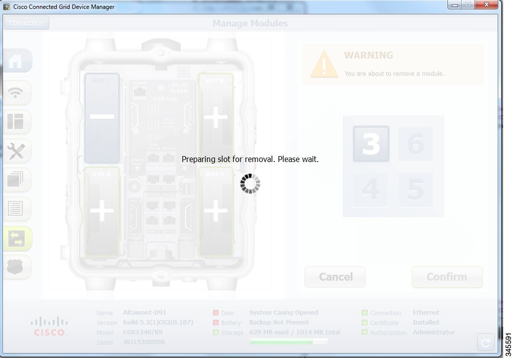
Step 2![]() To continue the removal, click Confirm.
To continue the removal, click Confirm.
The following message appears on the page:
Preparing slot for removal. Please wait.
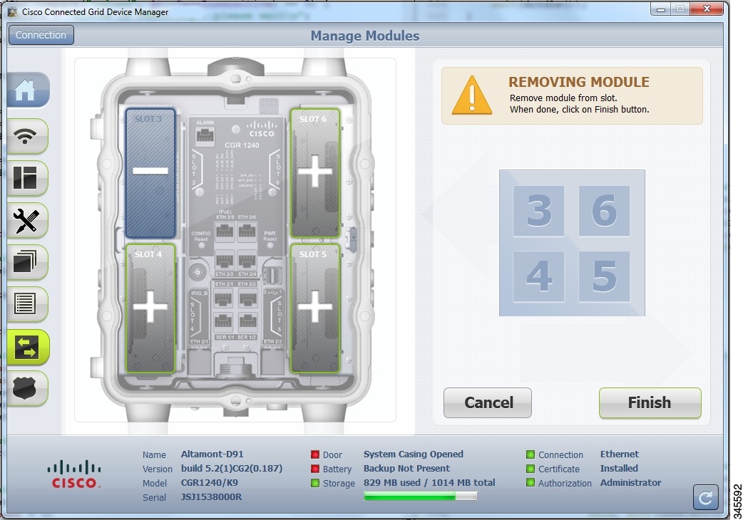
Step 3![]() When the Removing Module message appears, remove the module from the physical slot of the router.
When the Removing Module message appears, remove the module from the physical slot of the router.
The following message appears on the page to indicate an update to the configuration file is in process:
Removing module from slot. This process will take several minutes. Please wait.
Step 5![]() When the configuration update completes, a success message appears.
When the configuration update completes, a success message appears.
A plus (+) sign now appears in the slot where you physically removed the module indicating an empty slot.
Advanced Command
The Advanced Command task provides access to the CGR 1000 to fine-tune or troubleshoot the router. You must be familiar with Cisco CG-OS commands. For details on supported commands, refer to the CGR 1000 software configuration guides at: www.cisco.com/go/cgr1000-docs
Note![]() Not all interactive commands are supported. Configuration commands must be concatenated together, as follows:
Not all interactive commands are supported. Configuration commands must be concatenated together, as follows: configuration terminal ; interface ethernet2/1 ; shutdown ; end
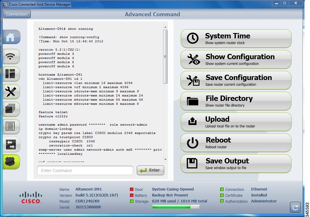
Step 1![]() From the At a Glance page, click Advanced Command. In addition to the advance console, you have the following choices:
From the At a Glance page, click Advanced Command. In addition to the advance console, you have the following choices:
- Click System Time to display the current setting of the system clock for the router.
- Click Show Configuration to display the current configuration of the router.
- Click Save Configuration to save the current router configuration to startup-config file.
- Click File Directory to display the router file directory.
- Click Upload to upload a new image file to the router.
- Click Reboot to reboot the router.
- Click Save Output to save the output displayed on the page to a file, windowslog.txt.
By default, the application saves the windowslog.txt file to the Documents folder.
(See WINDOWSLOG.TXT SAMPLE.)
Import Certificates
As admin, you can import certificates through the Device Manager by employing the Setup wizard or by command line. You will need to know the path to the certificate (.pfx) and the certificate password. The certificate password is created when the.pfx file is created. Generally, the admin downloads the.pfx file onto the Device Manager laptop.
The Setup wizard launches when either the user clicks the Settings icon on the opening page of the Device Manager or when the application does not detect a certificate.
To open the Import Certificate page, do the following:
Step 1![]() Step through the Setup wizard until you reach the Certificate Configuration page by clicking Next on each page. (See Setting Operating Mode.)
Step through the Setup wizard until you reach the Certificate Configuration page by clicking Next on each page. (See Setting Operating Mode.)
You do not need to change any values on the pages as you move through the pages.
Step 2![]() On the Certificate Configuration page, click Change Certificate.
On the Certificate Configuration page, click Change Certificate.
The Import Certificate page appears.
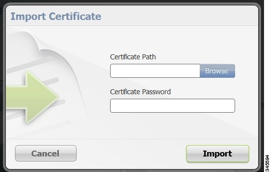
Step 3![]() On the Certificate Configuration page, browse to the location of the certificate file (.pfx) on your laptop.
On the Certificate Configuration page, browse to the location of the certificate file (.pfx) on your laptop.
Step 4![]() Enter the certificate password and then click Import.
Enter the certificate password and then click Import.
Disconnect from the CGR 1000
After finishing your work on the CGR 1000, click Connection (upper-left) to disconnect the
Device Manager from the router. The application opens the Connect to the Router page.
Connection Override
You only use the Connection Override option when you need to use different login information than that provided in the work order.
For example, the SSID or Passphrase for a WiFi connection might have changed since the work order was first created, but a new work order was not issued. In this case, the field technician might call the admin for that information and use Connection Override to enter that new information to log in to the router.
Optionally, the field technician can directly connect to the router by using the Over Ethernet option with the Auto Discover IP address option.
To change the login information, do the following:
Step 1![]() On the Work Authorization page, click Connection Override.
On the Work Authorization page, click Connection Override.
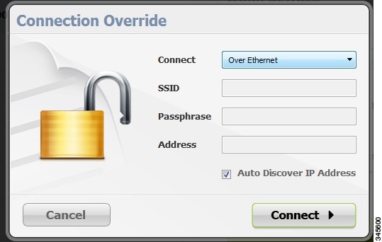
Step 2![]() In the Connection Override dialog box, select the connection type (Over Ethernet, Over WiFi, or Auto Detect) from the Connect drop-down menu.
In the Connection Override dialog box, select the connection type (Over Ethernet, Over WiFi, or Auto Detect) from the Connect drop-down menu.
Example Log File Output
This section contains output examples for files generated from the Retrieve Report and Advanced Command pages of the Device Manager.
WINDOWSLOG.TXT SAMPLE
The following example represents typical content that might be found in the windowslog.txt file generated from the Advanced Command page.
SYSTEMLOG.TXT SAMPLE
The following example represents typical content that might be found in a systemlog.txt file generated from the Retrieve Reports page.
Feature History
|
|
|
|
|---|---|---|
 Feedback