Segment Routing, Cisco IOS XE Everest 16.5.1 (Cisco ASR 900 Routers)
Bias-Free Language
The documentation set for this product strives to use bias-free language. For the purposes of this documentation set, bias-free is defined as language that does not imply discrimination based on age, disability, gender, racial identity, ethnic identity, sexual orientation, socioeconomic status, and intersectionality. Exceptions may be present in the documentation due to language that is hardcoded in the user interfaces of the product software, language used based on RFP documentation, or language that is used by a referenced third-party product. Learn more about how Cisco is using Inclusive Language.
- Updated:
- March 24, 2017
Chapter: Using Segment Routing with IS-IS
- Restrictions for Using Segment Routing with IS-IS
- Enabling Segment Routing
- Enabling Segment Routing for IGPs
- Prefix-SID Received in LSPs from Remote routers
- Segment Routing Adjacency SID Advertisement
- Segment Routing Mapping Server (SRMS)
- SRGB Range Changes
- MPLS Forwarding on an Interface
- Segment Routing and LDP Preference
- Segment Routing-TE
- RLFA LDP and SR
- Topology-Independent LFA
Using Segment Routing with IS-IS
We know that segment routing enables a node to select any path (explicit or derived from the computations of the internal gateway protocol’s shortest path). This path is not dependent on a hop-by-hop signaling technique (through LDP or RSVP), but on a set of segments that are advertised by a routing protocol, such as IS-IS or OSPF. These segments act as topological sub-paths that can be combined to form the desired path.
Segment Routing must be enabled before any IGP, such as IS-IS or OSPF, can configure segment routing functionality. Similarly, when segment routing is disabled, all IGP-related configuration is also disabled.
Restrictions for Using Segment Routing with IS-IS
- Effective Cisco IOS XE Release 3.16S, ISIS supports segment routing for IPv4 only.
- Segment routing must be configured at the top level before any routing protocol configuration is allowed under its router configuration sub mode.
- IS-IS protocol SR command is based on per topology (IPv4 address family).
- Only network type = point-to-point is supported.
Enabling Segment Routing
There are two levels of configuration required to enable segment routing for a routing protocol instance. The top level segment routing configuration which is managed by segment routing infrastructure component enables segment routing, whereas, segment routing configuration at the router level enables segment routing for a specific address-family of a routing protocol instance.
There are three segment routing states:
Segment routing configuration under the IGPs is allowed only if the SR state is either SR_DISABLED or SR_ENABLED. The SR_ENABLED state indicates that there is at least a valid SRGB range reserved through the MFI successfully.
Enabling Segment Routing for IGPs
You can enable segment routing for IGPs under the router configuration sub mode, through commands. However, IGP segment routing are enabled only after the global SR is configured.

Note![]() IS-IS protocol SR command is based on per topology (IPv4 address family).
IS-IS protocol SR command is based on per topology (IPv4 address family).
The SR_ENABLED is a necessary state for any protocol to enable SR, however, it is not a sufficient for enabling SR for a protocol instance. The reason being that the IS-IS still does not have any information about segment routing global block (SRGB) information. When the request to receive information about the SRGB is processed successfully, the IS-IS SR operational state is enabled
Segment Routing requires each router to advertise its segment routing data-plane capability and the range of MPLS label values that are used for segment routing in the case where global SIDs are allocated.
Data-plane capabilities and label ranges are advertised using the SR-capabilities sub-TLV inserted into the IS-IS Router Capability TLV-242 that is defined in RFC4971.
ISIS SR-capabilities sub TLV includes all reserved SRGB ranges. However, the Cisco implementation supports only one SRGB range.
The supported IPv4 prefix-SID sub TLV are TLV-135 and TLV-235.
Configuring Segment Routing on IS-IS
This section describes configuring segment routing IPV4 for IS-IS protocol under the router configuration sub mode.
Note![]() This command is allowed only when segment routing is configured at the top level.
This command is allowed only when segment routing is configured at the top level.
The following is an example of configuring IS-IS segment routing:
Prefix-SID Received in LSPs from Remote routers
Prefix SIDs received in a label switched path (LSP) with a reachability TLV (TLV 135 and 235) are downloaded to the routing information base (RIB) if all of the following conditions are met:
- Segment routing is enabled for the topology and address-family
- Prefix-SID is valid
- The local label binding to MFI is successful.
For a prefix-SID received with reachability TLVs (TLV 135 and 235), the label is downloaded through RIB the same way as BGP downloads per prefix VPN labels.
If the path is a remote LFA path, ISIS downloads the path the same way it downloads it before adding the segment routing functionality but does not download any label with this path. This behavior ensures that remote LFA functionality is still supported using LDP.
Limitations
- For SIDs that do not fit in the specified SID range, labels are not used when updating the RIB. For cases, where SID does fit in the SID range, but does not fit the next-hop neighbor SID range, remote label associated with that path is not installed.
- Node SIDs received in an LSP with reachability TLVs (TLV 135 and 235) are downloaded to RIB only if segment routing is enabled under the corresponding address-family.
- In case of multiple best next hops, if not all next hops support segment routing, ISIS will treat this instance similar to when mismatched labels are assigned to the same prefix. That is, IS-IS ignores the labels and installs unlabeled paths for all ECMP paths into the global RIB.
Segment Routing Adjacency SID Advertisement
Effective with Cisco IOS XE Release 3.17S, IS-IS supports the advertisement of segment routing Adjacency SID. An Adjacency Segment Identifier (Adj-SID) represents a router adjacency in Segment Routing.
A segment routing-capable router may allocate an Adj-SID for each of its adjacencies and an Adj-SID sub-TLV is defined to carry this SID in the Adjacency TLVs. IS-IS adjacencies are advertised using one of the IS-Neighbor TLVs below:
IS-IS allocates the adjacency SID for each IS-IS neighbor only if the IS-IS adjacency state is up and IS-IS segment routing internal operational state is enabled. If an adjacency SID allocation failure is due to out-of-label resource, IS-IS retries to allocate the Adj-SID periodically in a default interval (30 seconds).
Multiple Adjacency-SIDs
Effective with Cisco IOS XE Release 3.18S, multiple adjacency-SIDs are supported. For each protected P2P/LAN adjacency, IS-IS allocates two Adj-SIDs. The backup Adj-SID is only allocated and advertised when FRR (local LFA) is enabled on the interface. If FRR is disabled, then the backup adjacency-SID is released. The persistence of protected adj-SID in forwarding plane is supported. When the primary link is down, IS-IS delays the release of its backup Adj-SID until the delay timer expires. This allows the forwarding plane to continue to forward the traffic through the backup path until the router is converged.
Cisco IOS XE Release 3.18S, IS-IS Adj-SID is changed to be per level based since the forwarding plane is unaware of protocol-specific levels. The allocated and advertised backup Adj-SIDs can be displayed in the output of show isis neighbor detail and show isis data verbose commands.
Segment Routing Mapping Server (SRMS)
Segment Routing Mapping Server (SRMS) allows configuration and maintenance of the Prefix-SID mapping policy entries. Effective with Cisco IOS XE Release 3.17S, the IGPs use the active policy of the SRMS to determine the SID values when programming the forwarding plane.
The SRMS provides prefixes to SID/Label mapping policy for the network. IGPs, on the other hand, are responsible for advertising prefixes to SID/Label mapping policy through the Prefix-SID/Label Binding TLV. Active policy information and changes are notified to the IGPs, which use active policy information to update forwarding information.
Connected Prefix SIDs
Sometimes, a router may install a prefix with a SID that is different than what it advertises to the LSP. For example, if more than one protocol or more than one IGP instance is announcing the same prefix with different SIDs to the SRMS, the SRMS resolves the conflict and announces the winning prefix and SID that may not be the same as the local instance. In that case, the IGP always advertises what it learns from its source LSP although it still tries to install the SID which may be different than what it learns in its LSP. This is done to prevent the IGP from redistributing the SIDs from another protocol or another protocol instance.
Configuring IS-IS SRMS
The following command enables the IS-IS SRMS and allows IS-IS to advertise local mapping entries. IS-IS does not send remote entries to the SRMS library. However, IS-IS uses the SRMS active policy, which is computed based only on the locally configured mapping entries.
Configuring IS-IS SRMS Client
By default, the IS-IS SRMS client mode is enabled. IS-IS always sends remote prefix-sid-mapping entries received through LSP, to SRMS. The SRMS active policy is calculated based on both, local and remote mapping entries.
The following command disables the prefix-sid-mapping client functionality.
Configuring ISIS SID Binding TLV Domain Flooding
By default, the IS-IS SRMS server does not flood SID binding entries within the routing domain. In Cisco IOS XE Release 3.18S, the optional keyword domain-wide in the IS-IS SRMS server mode command to enable the SID and Label binding TLV flooding functionality.
The domain-wide keyword enables the IS-IS SRMS server to advertise SID binding TLV across the entire routing domain.
Note![]() The option is valid only if IS-IS SRMS performs in the SRMS server mode.
The option is valid only if IS-IS SRMS performs in the SRMS server mode.
SRGB Range Changes
When IS-IS segment routing is configured, IS-IS must request an interaction with the SRGB before IS-IS SR operational state can be enabled. If no SRGB range is created, IS-IS will not be enabled.
When an SRGB change event occurs, IS-IS makes the corresponding changes in its sub-block entries. IS-IS also advertises the newly created or extended SRGB range in SR-capabilities sub-TLV and updates the prefix-sid sub TLV advertisement.
Note![]() In Cisco IOS XE Release 3.16S only one SRGB range and SRGB extension for the modification are supported.
In Cisco IOS XE Release 3.16S only one SRGB range and SRGB extension for the modification are supported.
SRGB Deletion
When IS-IS receives an SRGB deletion event, it looks for an SRGB entry in the IS-IS SRGB queue list. If an SRGB entry does not exist, IS-IS makes sure that there is no pending SRGB created event. If a pending SRGB creation event is found, then IS-IS removes the SRGB creation event, and completes the SRGB delete processing,
If an SRGB entry is found in the IS-IS SRGB queue, IS-IS locks the SRGB, redistributes the RIBs and un-advertises all prefixed-SIDs that have SID value within the pending delete SRGB range, and un-advertises the SRGB range from SR-capabilities sub TLV. Once IS-IS has completed the SRGB deletion processing, it unlocks the SRGB and deletes the SRGB from its SR sub-block entry.
If there is no valid SRGB after the deletion of the SRGB, IS-IS SR operational state becomes disabled.
MPLS Forwarding on an Interface
MPLS forwarding must be enabled before segment routing can use an interface. IS-IS is responsible for enabling MPLS forwarding on an interface.
When segment routing is enabled for a IS-IS topology, or IS-IS segment routing operational state is enabled, IS-IS enables MPLS for any interface on which the IS-IS topology is active. Similarly, when segment routing is disabled for a IS-IS topology, IS-IS disables the MPLS forwarding on all interfaces for that topology.
Segment Routing and LDP Preference
In Cisco IOS XE Release 3.16S, the command sr-prefer is used to tell the forwarding interface to prefer using segment routing labels over LDP labels for all prefixes in a topology.
Segment Routing-TE
Segment Routing Traffic Engineering requires the IGP to provide segment routing related information to TE. The information includes SRGB, Adjacency-SID, Prefix-SID, primary and repair paths for all nodes in the topology.
The maximum number of allowed SR-TE tunnels are 510.
Enabling and Disabling SR-TE Announcements
IS-IS announces the SR information to TE when it detects that both, IS-IS SR and TE are enabled for at least one level. IS-IS announce only the information that is obtained from the level for which TE is configured.
Similarly, IS-IS instructs TE to delete all announcements when it detects that SR is not enabled or TE is no longer configured on any level.
RLFA LDP and SR
Consider the following topology.
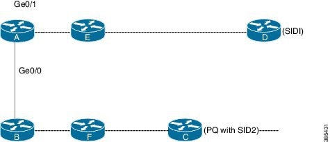
The traffic flows from A to D. The primary path is A-E-D and the primary next hop interface is Ge0/1. The secondary path is A-B-F-C-D, and C is the PQ node. The repair tunnel ends at PQ node C. The existing RLFA uses LDP TE tunnel for the repair path. When both LDP and SR are enabled, the LDP tunnel is used for RLFA repair path by default unless the segment routing preferred is configured through the sr-prefer command.
Topology-Independent LFA
When the local LFA and remote LFA are enabled, there is a good coverage of the prefixes to be protected. However, for some rare topologies that do not have a PQ intersect node, both local and remote LFA will fail to find a release node to protect the failed link. Furthermore, there is no way to prefer a post-convergence path, as the two algorithms have no knowledge of the post-convergence characteristics of the LFA.
To overcome the above limitation, effective Cisco IOS XE Release 3.18S, topology-independent LFA (TI-LFA) is supported on an SR-enabled network.
In Cisco IOS XE Release 3.18S, TI LFA supports the following:
- Link Protection—The LFA provides repair path for failure of the link.
- Local LFA—Whenever a local LFA on the post convergence path is available, it is preferred over TI-LFA because local LFA does not require additional SID for the repair path. That is, the label for the PQ node is not needed for the release node.
- Local LFA for extended P space—For nodes in the extended P space, local LFA is still the most economical method for the repair path. In this case, TI-LFA will not be chosen.
- Tunnel to PQ intersect node—This is similar to remote LFA except that the repair path is guaranteed on the post convergence path using TI-LFA.
- Tunnel to PQ disjoint node—This capability is unique to the TI-LFA in the case when local and remote LFA cannot find a repair path.
- Tunnel to traverse multiple intersect or disjoint PQ nodes, up to the platform’s maximum supported labels—TI-LFA provides complete coverage of all prefixes.
- P2P interfaces for the protected link—TI-LFA protects P2P interfaces.
- Asymmetrical links—The ISIS metrics between the neighbors are not the same.
- Multi-homed (anycast) prefix protection—The same prefix may be originated by multiple nodes.
- Protected prefix filtering—The route-map includes or excludes a list of prefixes to be protected and the option to limit the maximum repair distance to the release node.
- Tiebreakers—A subset of existing tiebreakers, applicable to TI-LFA, is supported.
Restrictions for the TI-LFA
Tie-breaker
Local and remote LFA use default or user-configured heuristics to break the tie when there is more than one path to protect the prefix. The attributes are used to trim down the number of repair paths at the end of the TI-LFA link protection computation before the load balancing.
Local LFA and remote-LFA support the following tiebreakers:
- linecard-disjoint—Prefers the line card disjoint repair path
- lowest-backup-path-metric—Prefers the repair path with lowest total metric
- node-protecting—Prefers node protecting repair path
- srlg-disjoint—Prefers SRLG disjoint repair path
- load-sharing—Distributes repair paths equally among links and prefixes
For TI-LFA link protection, the following tiebreakers are supported:
How it works: When there are two repair paths for a particular prefix, the path that the output port on different line card than that of the primary port is chosen as the repair path.
The following variant of the linecard-disjoint is supported:
–![]() LC disjoint index—If both the repair paths are on the same line card as that of the primary path, then, both paths are considered as candidates. If one of the path is on a different line card, then that path is chosen as the repair path.
LC disjoint index—If both the repair paths are on the same line card as that of the primary path, then, both paths are considered as candidates. If one of the path is on a different line card, then that path is chosen as the repair path.
The SRLG ID can be configured for each interface. When there are two repair paths for a prefix, the configured SRLG ID for the repair path is compared with that of the primary path SRLG ID. If the SRLG IDs for the secondary path is different than that of the primary, that path is chosen as the repair path.
Note![]() This policy comes into effect only when the primary path is configured with an SRLG ID.
This policy comes into effect only when the primary path is configured with an SRLG ID.
The following variant of the srlg-disjoint is supported:
–![]() srlg index—If both the repair paths have the same SRLG ID as that of the primary path, then, both the paths are considered as candidates. If one of the path has a different srlg id, then path is chosen as the repair path.
srlg index—If both the repair paths have the same SRLG ID as that of the primary path, then, both the paths are considered as candidates. If one of the path has a different srlg id, then path is chosen as the repair path.
- node-protecting—For TI-LFA node protection, the protected node is removed when computing the post-convergence shortest path. The repair path must direct traffic around the protected node.
It is possible to configure both node and SRLG protection modes for the same interface or the same protocol instance. In that case, an additional TI-LFA node-SRLG combination protection algorithm is run. The TI-LFA node-SRLG combination algorithm removes the protected node and all members of the interface with the same SRLG group when computing the post-convergence SPT.
For TI-LFA node protection, SRLG protection, and node-SRLG combination protection, it is likely the coverage for the protected prefixes is small. TI-LFA link protection is also run to provide coverage for the prefixes that not yet covered. However, optimization can be achieved when SRLG protection is enabled with no SRLG group on the interface. In that case, SRLG protection produces the same result as link protection and link protection is skipped. Furthermore, if node-protection is also configured in this case, TI-LFA node-SRLG combination protection produces the same result as node-protection and node-protection is skipped.
Interface FRR Tiebreakers
For TI-LFA node and SRLG protection, interface FRR tiebreakers must also be provided. Existing FRR tiebreakers are configured on a per protocol instance. Because FRR tiebreakers are not specific to TI-LFA, interface FRR tiebreakers are available for all FRR types. When both interface and protocol instance FRR tiebreakers are configured, the interface FRR tiebreakers take precedence over the protocol instance. When interface FRR tiebreakers are not configured, the interface inherits the protocol instance FRR tiebreakers. As with the existing tiebreakers, the priority must be unique among the interface and protocol instance for the tiebreakers.
The following interface FRR tiebreaker commands apply only to the particular interface.
Tie-breaker default and explicit tie-breaker on the same interface are mutually exclusive.
The following tie-breakers are enabled by default on all LFAs:
Effective with Cisco IOS XE Release 3.18S, node-protecting tie-breaker is disabled by default.
Limitations on Tie-Beakers
The following tie-breakers are not applicable for these LFA scheme.
Configuring T1 LFA
TI-LFA is disabled by default. There are two methods to enable TI-LFA:
1.![]() Using protocol enablement—Enable TI-LFA in router isis mode. This enables TI-LFA for all ISIS interfaces. Optionally, use the interface command to exclude the interfaces on which TI-LFA should be disabled.
Using protocol enablement—Enable TI-LFA in router isis mode. This enables TI-LFA for all ISIS interfaces. Optionally, use the interface command to exclude the interfaces on which TI-LFA should be disabled.
For example, to enable TI-LFA for all IS-IS interfaces:
The maximum-metric option specifies the maximum repair distance which a node is still considered eligible as a release node.
To disable TI-LFA on a particular interface:
Note![]() The isis fast-reroute protection level-x command enables local LFA and is required to enable TI-LFA.
The isis fast-reroute protection level-x command enables local LFA and is required to enable TI-LFA.
2.![]() Using interface enablement—Enable TI-LFA selectively on each interface
Using interface enablement—Enable TI-LFA selectively on each interface
When both interface and protocol are TI-LFA enabled, the interface configuration takes precedence over the protocol configuration.
Configuration Example
Example 1: In the following example, local LFA is configured with linecard-disjoint and srlg-disjoint tie-breakers. linecard-disjoint is given preference with a lower priority value (10) than the srlg-disjoint (11).
Example 2—Enable TI-LFA node-protecting tie-breaker on all ISIS level-2 interfaces with priority 100. All other tie-breakers are disabled.
Example 3—Enable TI-LFA node-protecting tie-breaker with priority 100 and TI-LFA SRLG protection with priority 200 on all IS-IS level-2 interfaces. All other tiebreakers are disabled because the node-protecting tie-breaker is configured.
Example 3—Enable TI-LFA node-protecting tie-breaker with priority 100 on all ISIS level-2 interfaces except on Ethernet0/0. For those IS-IS interfaces, all other tiebreakers are disabled. Ethernet0/0 overwrites the inheritance and uses the default set of tiebreakers with linecard-disjoint, lowest-backup-path-metric, srlg-disjoint enabled.
Example 4—Enable TI-LFA using the default tiebreaker on all IS-IS interfaces except on Ethernet0/0. On Ethernet0/0 enable TI-LFA node-protecting with priority 100 and disable all other tiebreakers.
Example 5—Enable TI-LFA node-protecting tie-breaker with priority 200 and linecard-disjoint tie-breaker with priority 100 on all ISIS level-2 interfaces. All other tiebreakers are disabled.
Verifying the Tie-breaker
To view tiebreakers are enabled on the interface:
Similarly, to view the tiebreakers enabled for the router mode:
Verifying the Primary and Repair Paths
In this example, 1.1.1.1 is the protecting neighbor and 4.4.4.4 is the neighbor on the protecting link.
Verifying the IS-IS Segment Routing Configuration
The command with keyword global-block displays the SRGB and the range for LSPs.
The show isis segment-routing prefix-sid-map command with keyword advertise displays the prefix-sid maps that the router advertises.
The show isis segment-routing prefix-sid-map command with keyword receive displays the prefix-sid maps that the router receives.
To display the connected-SIDs found in the LSPs and passed to the mapping server component, use the show isis segment-routing connected-sid command.
 Feedback