Cisco ASR 902 Router Features
The Cisco ASR 902 Router has the following hardware features:
- 2-RU modular chassis designed for installation in a 300-mm European Telecommunications Standards Institute (ETSI) cabinet
- Dedicated slots in the
chassis that support the following:
- Up to four interface modules
- One Route Switch Processor (RSP)
- Up to two DC or two AC or a combination of AC and DC power supply units
- One fan tray
- Network frequency, phase, and time inputs and outputs for network interfaces (SyncE and TDM), BITS, 1 PPS or 10 MHz and Timing over Packet (IEEE 1588-2008)
- Adjustable front and rear rail mounting locations
- Front panel access to power supplies, fan tray, RSP, and interface modules
- Online insertion and removal (OIR) of interface modules, power supplies, and fan tray
- Discrete status LEDs on power supply, interface module, RSP, and fan tray units
- Two alarm dry contact inputs (either normally open or normally closed)
- Environmental-monitoring and environmental-reporting functions
- LED indicators for critical, major, and minor alarms
- Side-to-side forced air cooling
- Temperature range of -40 to 149 degrees F (-40 to 65 degrees C) with 550W DC power supply
- Temperature range of 32 to 122 degrees F (-5 to 55 degrees C) with 550W AC power supply
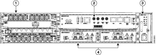
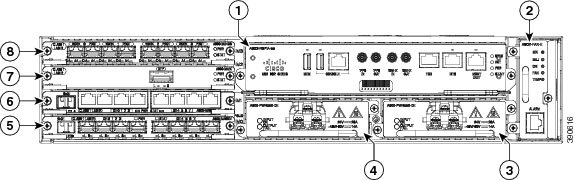
The figure below illustrates the Cisco ASR 902 Router chassis design.
|
Label |
Component |
|---|---|
|
1 |
Interface modules |
|
2 |
RSP unit |
|
3 |
Fan tray |
|
4 |
Redundant power units (two DC power units are shown) |
System Specifications
The table below summarizes the system specifications and environmental requirements for the Cisco ASR 902 Router.
|
Dimensions (Height x Width x Depth) |
3.56 in. x17.44 in. x 10.565 in. (90.424 x 442.976 x 268.351 mm)
|
||
|
Weight |
24.030 pounds (10.9 kg)
|
||
|
Operating Temperature |
The Cisco ASR 902 Router supports the following temperature ranges with the DC power supply:
The Cisco ASR 902 Router supports the following temperature ranges with the AC power supply:
|
||
|
Nonoperating Temperature |
–40 to 185ºF (–40 to +85ºC) storage temperature |
||
|
Operating Humidity |
5 to 95% operating noncondensing relative humidity |
||
|
Operating Altitude |
–60 to 1800m operating altitude for full operating temperature range; up to 4000m at up to 40ºC. |
||
|
Nonoperating Altitude |
4572m storage altitude |
||
|
Vibration |
1.0 g from 1.0 to 150 Hz |
||
|
Shock |
30 G half sine 6 and 11 ms |
||
|
Nonoperating Vibration |
Random: 1.15 gRMS 3 to 200 Hz, 30 minutes/axis Sine: 10 to 500 Hz @ 0.8 G peak/5 sweep cycles/axis |
||
|
Operating Acoustics |
< 68.5 dBa @ 27ºC |
Power Supply Features
The Cisco ASR 902 Router supports AC and DC power supplies. For more information about installing the Cisco ASR 902 Router power supplies, see the Installing the Power Supply section. The power sections provide more information about the power supply:
Redundancy
The Cisco ASR 902 Router chassis includes a slot for optional redundant power supply. The redundant power supply option provides a second power supply to ensure that power to the chassis continues uninterrupted if one power supply fails or input power on one line fails. Redundancy is supported either with identical power supplies or a combination of AC and DC power supply. The Cisco ASR 902 Router supports current sharing between the power supplies.
A redundant power supply on the Cisco ASR 902 Router is recommended. Each power supply should be connected to separate independent power sources to ensure that the router maintains power in the event of a power interruption caused by an electrical failure, a wiring fault, or a tripped circuit breaker.
 Caution |
To comply with IEC 61850-3 (voltage interruptions), redundant power supplies with separately derived power feeds are required. |
Dying Gasp
The Cisco ASR 902 Router DC power supply supports the Dying Gasp feature, which allows the router to provide an input power loss notification to the RSP so that the RSP can send appropriate SNMP traps or OAM messages and update log files on the router. With the DC power supply, the router supports a minimum input power loss detection time of 2 milliseconds (DC) and continued operation of at least 6 milliseconds (DC) after the notification.
 Note |
Continued DC power supply operation may vary for voltages other than +24/–48V. |
Note |
Dying Gasp is not supported on the ASR 900 RSP3 module with the 1200 W DC power supply. |
Status LEDs
LEDs are also provided on each power supply to indicate the status of the input power and the health of the power supply. For more information about the LEDs on the Cisco ASR 902 Router, see Troubleshooting.
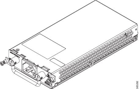
DC Power Specifications
The Cisco ASR 902 Router uses a +24/-48 DC voltage power supply (with DC voltage tolerance from -19 to -72 VDC).
The power supply provides 550W output power for the system. The power supply is field replaceable, hot swappable, and operates separately from the fan tray. The power supply contains a front panel with mounting screws, a handle for insertion and removal, and two status LEDs. No ON/OFF switch is provided.
The DC PSU models supported on the router are:
-
A900-PWR550-D—Uses an Euro-style three-position terminal block connector ( Figure 1-2 )
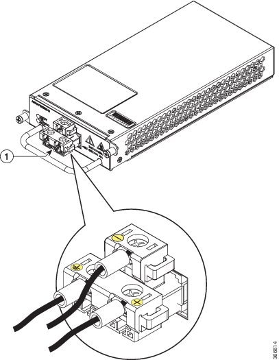
-
A900-PWR550-D-E—Uses a T-shaped connector ( Figure 1-3 )
-
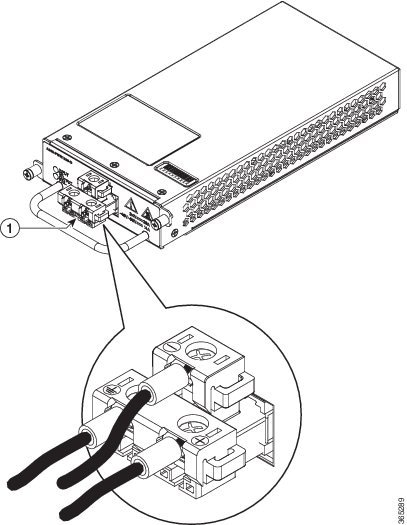
A900-PWR1200-D—Provides 975 W output power for system 12 V power with the A902-FAN-E module. As most of the system configurations using A900-RSP3C-200-S RSP modules require power exceeding 550 W, we recommend using the A900-PWR1200-D power supply with A900-RSP3C-200-S RSP modules. ( Figure 1-4 )
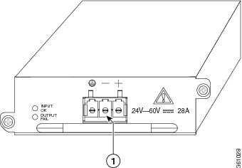
|
Label |
Component |
|---|---|
|
1 |
Euro-style connector |
|
Label |
Component |
|---|---|
|
1 |
T-shaped connector |
|
Part numbers |
A900-PWR550-D, A900-PWR550-D-E |
|
Nominal input voltage specification |
+24 VDC/–48 VDC |
|
Input voltage range |
–19.2 VDC to –72 VDC |
|
Output voltage |
+12 VDC |
|
Wire gauge for DC input power connections |
12 AWG minimum for –48/-60 VDC 8 AWG minimum for 24 VDC Connector accepts 8 AWG maximum |
|
Maximum power output |
550 W |
|
Label |
Component |
|---|---|
|
1 |
T-shaped connector |
|
Part numbers |
A900-PWR1200-D |
|
Nominal input voltage specification |
48V, GND, -48V |
|
Input voltage range |
-40.8 VDC to -72 VDC |
|
Output voltage |
+12 VDC |
|
Wire gauge for DC input power connections |
8-10 AWG minimum for -48/-60 VDC. Connector accepts 8 AWG maximum. |
|
Maximum power output |
1200 W 975W with A902-FAN-E |
AC Power Specifications
The AC PSU models supported on the router are:
-
A900-PWR550-A—Provides 550 W power
-
A900-PWR1200-D—Provides 1200 W power
The table below summarizes the input power specifications for the Cisco ASR 902 Router AC power supply units.
|
Part number |
A900-PWR550-A |
|
Input power specification |
115VAC/ 230VAC |
|
Input voltage |
85/264 VAC |
|
Minimum input voltage |
85 VAC |
|
Maximum input voltage |
264 VAC |
|
Minimum output voltage |
12 VDC |
|
Maximum output voltage |
12.4 VDC |
|
Maximum power output |
550 W |
-
A900-PWR1200-A—Provides 975 W output power for system 12 V power with the A902-FAN-E module. As most of the system configurations using A900-RSP3C-200-S RSP modules require power exceeding 550 W, we recommend using the A900-PWR1200-A power supply with A900-RSP3C-200-S RSP modules. ( see the figure below )
|
Part number |
A900-PWR1200-A |
|
Input power specification |
115VAC/ 230VAC |
|
Input voltage |
85/264 VAC |
|
Minimum input voltage |
85 VAC |
|
Maximum input voltage |
264 VAC |
|
Minimum output voltage |
12V |
|
Maximum output voltage |
12.4V |
|
Maximum power output |
1200 W 975W with A902-FAN-E |
Fan Tray
The fan tray has the following hardware features:
- It provides side-to-side forced air cooling
- It provides redundant fans
- It is field replaceable
- It contains status LEDs
- It contains two alarm ports with two external alarm inputs
The fan tray modules supported on the router are:
- A902-FAN-E ( Figure 1-6 )
For more information about air flow guidelines, see the Air Flow Guidelines section . For instructions on how to install the fan tray, see the Installing the Fan Tray section. For a summary of the LEDs on the fan tray, see the LED Summary section .
Fan Tray (A902-FAN-E)
The Cisco ASR 902 Router uses a modular fan tray that is separate from the power supply. The A902-FAN-E is a fan tray containing eight (40 x 40 x 20 mm) fans and provides sufficient capacity to maintain operations indefinitely in the event of an individual fan failure. It has a 8-mm fan dust filter that prevents dust from entering the unit and avoids possible damage to the components. The fan tray is IEC60950-1 compliant.
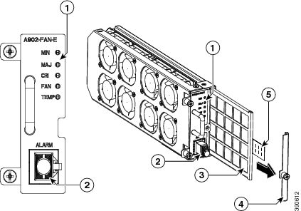
|
Label |
Component |
Label |
Component |
|---|---|---|---|
|
1 |
Label |
4 |
Dummy cover |
|
2 |
Alarm |
5 |
Pull tab |
|
3 |
Dust filter |
— |
— |
Dust Filter (A902-FAN-F)
The dust filter (as shown in the figure in Fan Tray (A902-FAN-E section) on the fan tray is a quadrafoam 45PPI filter that is 85 percent dust resistant. A dummy cover (A902-FAN-F-B) secures the dust filter in the chassis. For installing the fan filter, see the Installing the Dust Filter section.
Note |
Use the pull tab to easily access the filter. |
Air Plenum
Air plenum or air baffle assembly is used to change the air flow pattern of the unit. When the router is installed with the plenum, the air flow pattern is changed from side-side to front-back. The front-back air flow pattern provides a rack installation bay with a cool front zone and a hot rear zone. For information about installing the plenum, see Installing the Router Chassis in the Air Plenum.
Note |
When the air plenum and the fan filter are installed in the chassis, the system’s maximum operating temperature should be 55 degrees Celsius. |
To order an air plenum, contact the Sales and Marketing staff at GAW (www.GawTechnology.net) (see Table A-2).
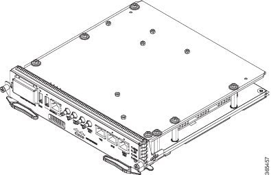
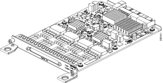
RSP Modules
The Cisco ASR 902 Router is designed to use a single RSP module to handle the data plane, network timing, and control plane functionalities for the router. The RSP configuration allows you to use Cisco IOS software to control chassis management, external management, and system status indications on the router.
RSP features include:
- Loading software onto processor-based interface modules
- Packet processing
- Traffic management, including buffering, queuing, and scheduling, Ethernet MAC functions.
- Network clocking functions, including phase and time-of-day for Building Integrated Timing Source (BITS), 1 PPS, 10 MHz, and 1588 Precision Time Protocol (PTP) clock references.
- Storage of software images, system configuration, Onboard Failure Logging (OBFL), syslog.
- PTP packet processing, including IEEE 1588-2008 for recovering network timing (frequency, phase, and time) from upstream PTP clocks for generating PTP frequency and phase references as inputs to the Synchronous Equipment Timing Source (SETS), and for distributing them to downstream PTP clocks.
- External management interfaces (RS232 console, management ENET, USB console, USB storage) and system-status LED indicators.
Supported RSPs
The Cisco ASR 902 Router supports the following RSPs:
-
A900-RSP2A-128—Provides 4-GB double data rate type three (DDR3) memory and 128-Gbps aggregate throughput.
-
A900-RSP2A-64—Provides 4-GB double data rate type three (DDR3) memory and 64-Gbps aggregate throughput.
-
A900-RSP3C-200-S—Provides 8 GB DDR3 memory, 64MB flash memory, 20 Mb of TCAM memory, 8 GB of SDRAM, 200 Gbps throughput, and a USB port for mass storage on the faceplate.
The Cisco ASR 902U Router supports the following RSPs:
-
A900U-RSP2A-128—Provides 4-GB double data rate type three (DDR3) memory and 128-Gbps aggregate throughput.
-
A900U-RSP2A-64—Provides 4-GB double data rate type three (DDR3) memory and 64-Gbps aggregate throughput.
Caution |
The SD memory card is not field replaceable. Do not try to remove or replace it. |
Note |
The supported RSPs have different memory capacities, but they have the same interfaces and functionalities. |
A900-RSP2-Supported Interface Modules (ASR 902 Router)
|
RSP |
Interface Modules |
Part Numbers |
Slots |
|---|---|---|---|
|
A900-RSP2A-128 A900U-RSP2A-128 |
8-port Gigabit Ethernet SFP Interface Module (8x1GE) |
A900-IMA8S |
All |
|
8-port Gigabit Ethernet RJ45 (Copper) Interface Module (8x1GE) |
A900-IMA8T |
||
|
1-port 10-Gigabit Ethernet XFP Interface Module (1x10GE) |
A900-IMA1X |
||
|
16-port T1/E1 Interface Module |
A900-IMA16D |
||
|
4-port OC3/STM-1 (OC-3) or 1-port OC12/STM-4 (OC-12) Interface Module |
A900-IMA4OS |
||
|
SFP Combo IM—8-port Gigabit Ethernet (8x1GE) + 1-port 10-Gigabit Ethernet (1x10GE) |
A900-IMA8S1Z |
||
|
Copper Combo IM—8-port Gigabit Ethernet (8x1GE) + 1-port 10-Gigabit Ethernet Interface Module (1x10GE) |
A900-IMA8T1Z |
||
|
2-port 10 Gigabit Ethernet Interface Module (2x10GE) |
A900-IMA2Z |
||
|
14-port Serial Interface Module |
A900-IMASER14A/S |
||
|
4-port C37.94 Interface Module |
A900-IMA4C3794 |
||
|
A900-RSP2A-64 A900U-RSP2A-64 |
1-port 10 Gigabit Ethernet XFP Interface Module (1x10GE) |
A900-IMA1X |
0-2 |
|
2-port 10 Gigabit Ethernet Interface Module (2x10GE) |
A900-IMA2Z |
||
|
4-port OC3/STM-1 (OC-3) or 1-port OC12/STM-4 (OC-12) Interface Module |
A900-IMA4OS |
||
|
8-port Gigabit Ethernet SFP Interface Module (8x1GE) |
A900-IMA8S |
0, 2 and 3 | |
|
8-port Gigabit Ethernet RJ45 (Copper) Interface Module (8x1GE) |
A900-IMA8T |
||
|
16-port T1/E1 Interface Module |
A900-IMA16D |
||
|
32-port T1/E1 Interface Module |
A900-IMA32D |
||
|
8-port T1/E1 Interface Module |
A900-IMA8D |
||
|
6-port E & M Interface Module |
A900-IMA6EM |
||
|
14-port Serial Interface Module |
A900-IMASER14A/S |
||
|
4-port C37.94 Interface Module |
A900-IMA4C3794 |
A900-RSP3C-200-S Supported Interface Modules (ASR 902 Router)
|
RSP Module |
Supported Interface Modules |
Part Numbers |
Slot |
|---|---|---|---|
|
A900-RSP3C-200-S |
8-port Gigabit Ethernet SFP Interface Module (8x1GE) |
A900-IMA8S |
All1 |
|
8-port Gigabit Ethernet RJ45 (Copper) Interface Module (8x1GE) |
A900-IMA8T |
||
|
1-port 10 Gigabit Ethernet XFP Interface Module (1x10GE) |
A900-IMA1X |
0 and 1 |
|
|
SFP Combo IM—8-port Gigabit Ethernet (8x1GE) + 1-port 10 Gigabit Ethernet (1x10GE) |
A900-IMA8S1Z |
All |
|
|
Copper Combo IM—8-port Gigabit Ethernet (8x1GE) + 1-port 10 Gigabit Ethernet Interface Module (1x10GE) |
A900-IMA8T1Z |
||
|
2-port 10 Gigabit Ethernet Interface Module (2x10GE) |
A900-IMA2Z |
||
|
8-port 10 Gigabit Ethernet Interface Module (8x10GE) |
A900-IMA8Z |
0 |
|
|
2-port 40 Gigabit Ethernet QSFP Interface Module (2x40GE) |
A900-IMA2F |
Supported RSP Features
The following are the RSP features supported on the Cisco ASR 902 Router:
- Centralized data plane, timing, and control plane functions for the system
- High-level control of interface modules
- Management functionalities for the router
- Control plane (host) CPU and associated memory in which Cisco IOS-XE and platform-control software run
- Nonvolatile memory for storage of software images, configurations, and system files
- Enabling and monitoring the health and presence of fan trays, interface modules, and power supplies
- Field replacement
Network Timing Interfaces
The RSP supports the following network timing interfaces:
- BITS input/output port—RJ48 jack
- 1 PPS input and output—Mini coax connectors
- 2.048 or 10 MHz input and output—Mini coax connectors
- Time of Day (ToD) —Shielded RJ45 jack
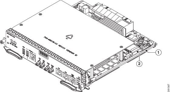
RSP Interfaces
The figure below summarizes the interfaces on an RSP module.
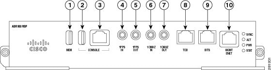
|
Label |
Interface |
|---|---|
|
1 |
USB memory port |
|
2 |
USB console port |
|
3 |
Console port |
|
4 |
1-PPS input timing port |
|
5 |
1-PPS output timing port |
|
6 |
10-MHz input timing port |
|
7 |
10-MHz output timing port |
|
8 |
ToD timing port |
|
9 |
BITS timing port |
|
10 |
Ethernet management port |
The A900-RSP2A has the following front panel interfaces. For information on cable pinouts, see Pinouts.
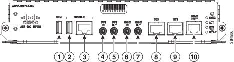
- 1 USB Type-A Connector for USB flash (Label = MEM)
- 1 USB Type-A Connector for alternate console port (Label = CONSOLE)
- RJ45 Connector for Con/Aux (Label = CONSOLE)
- RJ48 Jack for BITS interface (Label = BITS)
- RJ48 Jack for Time-of-Day interface (Label= TOD)
- RJ45 Connector for Con/Aux (Label = MGMT ENET)
- 4 Mini-Coax Connectors (Label = 1PPS IN, 1PPS OUT, 10MHZ IN, 10MHZ OUT)
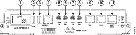
|
Label |
Interface |
|---|---|
|
1 |
GNSS module slot (optional) |
|
2 |
USB memory port |
|
3 |
USB console port |
|
4 |
Console port |
|
5 |
1-PPS input timing port |
|
6 |
1-PPS output timing port |
|
7 |
10-MHz input timing port |
|
8 |
10-MHz output timing port |
|
9 |
ToD timing port |
|
10 |
BITS timing port |
|
11 |
Ethernet management port |
For more information about installing an RSP, see the RSP Installation section. For more information about RSP LEDs, see the RSP LEDs section.
GNSS Module (A900-CM-GNSS)
The GNSS module is present on the RSP3 modules. It is a pluggable module that allows direct interface with the external antenna.
DANGER |
To reduce the risk of fire, use only No. 26 AWG or larger telecommunication line cord. Statement 1023 |
Note |
The GNSS module is not hot swappable. |
GNSS Module RF Input Requirements
- The GNSS module requires an
active GPS/GNSS antenna with built-in Low-Noise Amplifier (LNA) for optimal
performance. The antenna LNA amplifies the received satellite signals for two
purposes:
-
Compensation of losses on the cable
-
Lifting the signal amplitude in the suitable range for the receiver frontend
The Amplification required is 22dB gain + cable/connector loss + Splitter signal loss.
The recommended range of LNA gain (LNA gain minus all cable and connector losses) at the connector of the receiver module is 22dB to 30dB with a minimum of 20dB and a maximum of 35dB.
-
-
GNSS module provides 5V to the active antenna through the same RF input.
-
Surge requirement:
-
GNSS modules have built-in ESD protections on all pins, including the RF-input pin. However, additional surge protection may be required if rooftop antennas are being connected, to meet the regulations and standards for lightning protection in the countries where the end-product is installed.
-
A lightning protection must be mounted at the place where the antenna cable enters the building. The primary lightning protection must be capable of conducting all potentially dangerous electrical energy to PE (Protective Earth).
-
Surge arrestors should support DC-pass and suitable for the GPS frequency range (1.575GHz) with low attenuation.
-
-
Antenna Sky visibility:
-
GPS signals can only be received on a direct line of sight between antenna and satellite. The antenna should see as much as possible from the total sky. For proper timing, minimum of four satellites should be locked.
Note
The antenna terminal should be earthed at the building entrance in accordance with the ANSI/NFPA 70, the National Electrical Code (NEC), in particular Section 820.93, Grounding of Outer Conductive Shield of a Coaxial Cable.
-
-
Use a passive splitter if more than one GNSS modules are fed from a single antenna.
Note |
The splitter should have all the RF ports capable of DC-pass, if the antenna needs to feed power from GNSS module. |
For information on pinout, see GPS Port Pinouts.
Interface Modules
The Cisco ASR 902 Router interface modules are field-replaceable units.
Note |
On RSP-1, Slot 2 Port 0 cannot be used for traffic flow on 8X1-G copper and 8X1-G SFP interface modules. To identify Slot 2 on a Cisco ASR 902 Router, see the figure in the Interface Numbering section. |
In addition to the ports provided on an RSP, the Cisco ASR 902 Router supports the following interface modules:
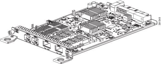
Gigabit Ethernet SFP Interface Module
The Gigabit Ethernet Small Form-Factor Pluggable (SFP) interface module provides eight Gigabit Ethernet SFP modules. The figure below shows the 8-port 1Gigabit Ethernet SFP interface module.
For information on supported SFP modules, see Cisco ASR 900 Series Aggregation Services Routers Data Sheet.
For more information about installing an SFP Gigabit Ethernet module, see the Interface Module Installation.
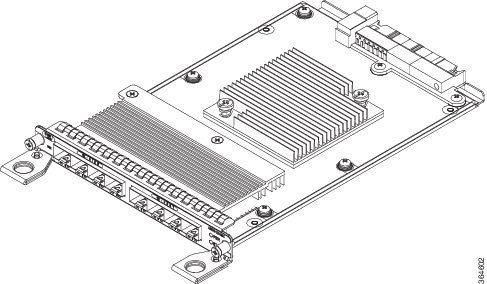
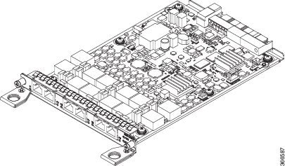
Gigabit Ethernet RJ45 Interface Module
The Gigabit Ethernet RJ45 interface module provides eight Gigabit Ethernet copper ports. The figure below shows the interface module.
For information on supported SFP modules, see Cisco ASR 900 Series Aggregation Services Routers Data Sheet.
For more information about installing an RJ45 Gigabit Ethernet module, see the Interface Module Installation.
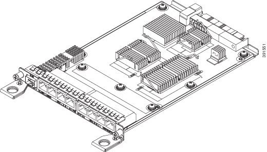
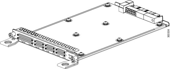
1-Port 10-Gigabit Ethernet XFP Interface Module
The 10-Gigabit Ethernet XFP interface module provides a single port supporting a 10-Gigabit Ethernet XFP module. The figure below shows the interface module.
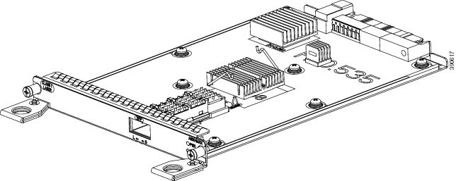
For information on supported SFP modules, see Cisco ASR 900 Series Aggregation Services Routers Data Sheet.
For more information about installing a 10-Gigabit Ethernet XFP module, see the Interface Module Installation.
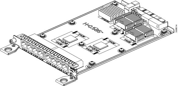
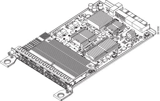
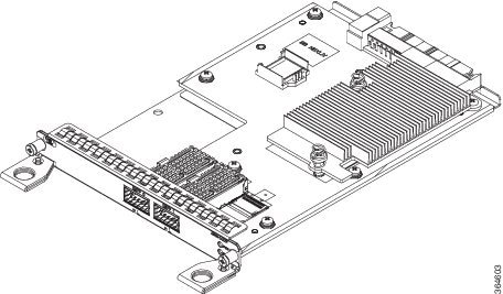
16-Port T1/E1 Interface Module
The 16-port T1/E1 interface module provides connectivity for up to 16 T1/E1 ports through a 100-pin Amplimite connector. The T1/E1 interface module requires the use of a patch panel to provide RJ48 (T1) or BNC (E1) connectors. The figure below shows the interface module.
For information on supported SFP modules, see Cisco ASR 900 Series Aggregation Services Routers Data Sheet.
For more information about installing a T1/E1 interface module, see theInterface Module Installation.
4-port OC3/STM-1 (OC-3) or 1-port OC12/STM-4 (OC-12) Interface Module
The 4-port OC3/STM-1 (OC-3) or 1-port OC12/STM-4 (OC-12) interface module can operate as up to four STM-1 interfaces.
Note |
The optical interface module is designed for both OC-3 and OC-12 traffic. |
The figure below shows the 4-port OC-3 interface module.
For information on supported SFP modules, see Cisco ASR 900 Series Aggregation Services Routers Data Sheet.
For more information about installing an optical interface module, see the Interface Module Installation.
For more information about using the LEDs to troubleshoot the Cisco ASR 902 Router, see Troubleshooting.
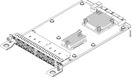
8x1 Gigabit Ethernet SFP + 1x10 Gigabit Ethernet SFP+ Combination Interface Module
The 8-port 1 Gigabit Ethernet SFP interface module with the 1-port 10 Gigabit Ethernet interface module is a high-density combination interface module. This module supports eight 1-Gigabit Ethernet SFP ports and one 10-Gigabit Ethernet SFP+ port.
For information on supported SFP modules, see Cisco ASR 900 Series Aggregation Services Routers Data Sheet.
For more information about installing the 8X1 GE SFP + 1X10 SFP Gigabit Ethernet module, see the Interface Module Installation.
8x1 Gigabit Ethernet RJ45 + 1x10 Gigabit Ethernet SFP+ Combination Interface Module
This 8-port 1 Gigabit Ethernet RJ45 (Copper) interface module with the 1-port 10 Gigabit Ethernet interface module is a high-density combination interface module. This module supports eight 1 Gigabit Ethernet Copper ports and one 10 Gigabit Ethernet SFP+ port.
For information on supported SFP modules, see Cisco ASR 900 Series Aggregation Services Routers Data Sheet.
For more information about installing the 8X1 GE RJ45 + 1X10 SFP Gigabit Ethernet module, see the Interface Module Installation.
8-Port 10 Gigabit Ethernet Interface Module (8x10GE)
The high density 8x10 Gigabit Ethernet interface module supports eight 10 Gigabit Ethernet ports using SFP+ transceivers cages on the faceplate.
Note |
It does not support XFP transceivers on the ports. |
For information on supported SFP modules, see Cisco ASR 900 Series Aggregation Services Routers Data Sheet.
For more information about installing a 8X10GE module, see the Interface Module Installation.
2-Port 10 Gigabit Ethernet SFP+ Interface Module (2x10 GE)
The 2-port 10 Gigabit Ethernet interface module provides a dual port supporting a 10 Gigabit Ethernet SFP+ and XFP module.
For information on supported SFP modules, see Cisco ASR 900 Series Aggregation Services Routers Data Sheet.
For more information about installing the 2X10 GE SFP Gigabit Ethernet module, see the Interface Module Installation.
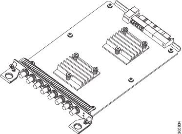
2-Port 40 Gigabit Ethernet QSFP Interface Module (2x40 GE)
The dual port 40 Gigabit Ethernet interface module supports the 40 Gigabit Ethernet port. The 40G interface is supported using QSFP+ optics. The figure below shows the interface module.
For information on supported SFP modules, see Cisco ASR 900 Series Aggregation Services Routers Data Sheet.
For more information about installing a 2X40GE module, see the Interface Module Installation.
14-Port Serial Interface Module
The Cisco (A900-IMASER14A/S) is a 14-port serial interface module for the router. The Cisco ASR 902 Router module has the following interfaces:
-
12-in-1 Connector (6)—Supports synchronous and asynchronous RS-232 interfaces using EIA/TIA-232 DB-25 connectors.
-
68-Pin Connector (2)—Supports up to 8 RS-232 interfaces in full or half duplex mode using 4 RS-232 connectors (DB-25, DB-9, or RJ-45).
|
1 |
Captive screws (2) |
2 |
68-Pin Connector (2) |
|
3 |
12-in-1 Connector (6) |
4 |
Status (STAT) LED |
|
5 |
Power (PWR) LED |
6 |
LEDs—The LEDs are as follows:
|
Supported Standards
The 14-port serial interface module supports the following standards:
|
Standard |
Definition |
|---|---|
|
IEEE 1613 2009 |
IEEE Standard for Environmental and Testing Requirements for Communications Networking Devices in Electric Power Substations |
|
IEC 61850-3 |
IEC standard specifying general requirements for substation automation systems (SAS) communications and related system requirements. |
|
IEC 60870-2-1:1995 |
IEC standard for substation environmental conditions |
|
IEC 60870-2-2:1996 |
IEC standard for substation environmental conditions |
|
IEC 61000-6-5:2001 |
IEC standard defining immunity for power station and substation environments |
For more information about installing the module, see the Interface Module Installation.
For information on LEDs, see 14-Port Serial Interface Module LEDs.
For information on cables and pinouts see, Connecting Serial Cables and Serial Interface Modules Pinouts.
6-Port E and M Interface Module
The Cisco A900-IMA6EM is a 6-port Ear and Mouth (E&M) interface module. The interface module provides the router with connectivity to tele-protection equipments. The front panel of the module consists of:
-
six port RJ45 connectors
-
two LED that display Power and Status
-
one LED per RJ45 port
This image is not available in preview/cisco.com
For more information about installing the module, see the Interface Module Installation section.
4-Port C37.94 Interface Module
The Cisco (A900-IMA4C3794) is a 4-port interface module that provides IEEE C37.94-2002 compliant Nx64 kbps optical interface ports to the router. The interfaces support 50/62.5 multimode fiber at 850 nm. The physical interfaces use 2.5 mm ST connectors.
The front panel of the module consists of:
-
four ports of IEEE C37.94 interfaces
For more information about installing the module, see the Interface Module Installation section .
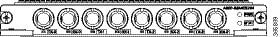
G.703/FXS/FXO Interface Module
The G.703/FXS/FXO Interface Module (A900-IMAG703FXSO) is a three port FXS, two port FXO, and three port G.703 64-Kbps co-directional interface module.
 Warning |
To reduce the risk of fire, use only No. 26 AWG or larger telecommunication line cord. Statement 1023 |
For information on LEDs, see G.703/FXS/FXO Interface Module LEDs .
For more information about installing the module, see Interface Module Installation.
G.703/FXS/FXO Interface Module Connectors
-
One dual-port RJ11 FXO connector
-
One 6-port RJ45 connector (shared between FXS and G.703)
Blank Deflector (A900-IMA-BLNK-DEF)
The A900-IMA-BLNK-DEF is a special type of blank filler plate that can be used in empty interface module slots. In addition to just acting as a filler for the empty slots in the router, this blank deflects additional air towards the interface modules in the slot below it, thereby enhancing the cooling for the interface module.
Caution |
The A900-IMA-BLNK-DEF module should not be used in slot 0 in the Cisco ASR 902 Router. |
For slot 0, always use the filler blank (A900-IMA-BLANK) when a blank filler needs to be used.
For more information on operating temperature, see Maximum Operating Ambient Temperature Support for RSP3 Modules .
Maximum Operating Ambient Temperature Support for RSP3 Modules
The router supports multiple fan trays with different cooling capacities. The maximum operating temperature of the router using the RSP3 modules, depends on the fan tray and the interface modules used in the router.
The table below provides an overview of the operating ambient temperature limits for different interface modules with A900-RSP3C-200-S in the router.
Note |
The temperature range could be further restricted by the optical modules used in the router. |
|
Interface Modules |
Fan Tray |
Operating Temperature Limit (°C) |
|---|---|---|
|
A900-IMA1X A900-IMA8T A900-IMA8S A900-IMA2Z A900-IMA8T1Z A900-IMA8S1 |
A902-FAN-E |
–40 to 65 |
|
A900-IMA8Z |
–40 to 50 |
|
|
A900-IMA2F |
–40 to 45 |
Temperature Sensor
The Cisco ASR 902 Router has a temperature sensor to detect overtemperature conditions inside the chassis. The overtemperature detection trips at 75°C +/– 5% with the ambient (inlet) trip point at 67°C. This condition is reported to the processor as an interrupt, and the software takes action to generate the appropriate alarms.
Temperature Sensors on the A900 RSP3 modules
The maximum operating temperature of the RSP3 module and the interface modules is less than the maximum operating temperature of the router. The IOS software decides the appropriate temperature thresholds to generate warnings, and shuts down the system when abnormally high temperature is detected.
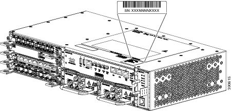
Serial Number Label Location
The figure below shows the serial number label location on the Cisco ASR 902 Router.
 Feedback