Cisco Unified Border Element (SP Edition) Configuration Guide: Unified Model
Bias-Free Language
The documentation set for this product strives to use bias-free language. For the purposes of this documentation set, bias-free is defined as language that does not imply discrimination based on age, disability, gender, racial identity, ethnic identity, sexual orientation, socioeconomic status, and intersectionality. Exceptions may be present in the documentation due to language that is hardcoded in the user interfaces of the product software, language used based on RFP documentation, or language that is used by a referenced third-party product. Learn more about how Cisco is using Inclusive Language.
- Updated:
- February 25, 2010
Chapter: Implementing Firewall Traversal and NAT
Implementing Firewall Traversal and NAT
Cisco Unified Border Element (SP Edition) enables voice over IP (VoIP) signaling and media to be received from and directed to a device behind a firewall and NAT (Network Address Translator) at the border of an adjacent network, without requiring the device or firewall to be upgraded. Cisco Unified Border Element (SP Edition) achieves this by rewriting the IP addresses and ports in the call signaling headers and the Session Description Protocol (SDP) blocks attached to these messages. Cisco Unified Border Element (SP Edition) does not support options for keeping pinholes open. Instead, Cisco Unified Border Element (SP Edition) registers messages for signaling pinhole maintenance and Real-Time Protocol (RTP) packets for media.
Cisco Unified Border Element (SP Edition) supports the Session Initiation Protocol (SIP) extension for Symmetric Response Routing (RFC 3581). There is no support for H.323 in Cisco IOS Release 2.4 and earlier.

Note ![]() For Cisco IOS XE Release 2.4, this feature is supported in both the unified and distributed models.
For Cisco IOS XE Release 2.4, this feature is supported in both the unified and distributed models.
Cisco Unified Border Element (SP Edition) was formerly known as Integrated Session Border Controller and may be commonly referred to in this document as the session border controller (SBC).
For a complete description of the commands used in this chapter, refer to the Cisco Unified Border Element (SP Edition) Command Reference: Unified Model at:
http://www.cisco.com/en/US/docs/ios/sbc/command/reference/sbcu_book.html.
For information about all Cisco IOS commands, use the Command Lookup Tool at http://tools.cisco.com/Support/CLILookup or a Cisco IOS master commands list.
Feature History for Implementing Firewall Traversal and NAT
|
|
|
Cisco IOS XE Release 2.4 |
This feature was introduced on the Cisco IOS XR along with support for the unified model. |
Contents
This chapter contains the following sections:
•![]() Prerequisites for Implementing Firewall Traversal and NAT
Prerequisites for Implementing Firewall Traversal and NAT
•![]() Information About Firewall Traversal and NAT
Information About Firewall Traversal and NAT
•![]() Implementing Firewall Traversal and NAT
Implementing Firewall Traversal and NAT
•![]() Configuration Example of Implementing Firewall Traversal and NAT
Configuration Example of Implementing Firewall Traversal and NAT
Prerequisites for Implementing Firewall Traversal and NAT
The following prerequisites are required to implement firewall traversal and NAT:
•![]() Before implementing firewall traversal and NAT, Cisco Unified Border Element (SP Edition) must already be configured.
Before implementing firewall traversal and NAT, Cisco Unified Border Element (SP Edition) must already be configured.
•![]() Adjacencies must be configured before implementing firewall traversal and NAT. See the procedures described in Chapter "Implementing Adjacencies on Cisco Unified Border Element (SP Edition)."
Adjacencies must be configured before implementing firewall traversal and NAT. See the procedures described in Chapter "Implementing Adjacencies on Cisco Unified Border Element (SP Edition)."
Information About Firewall Traversal and NAT
Firewall Traversal
Cisco Unified Border Element (SP Edition) enables VoIP signaling and media to be received from and directed to a device behind a firewall and NAT at the border of an adjacent network, without requiring the device or firewall to be upgraded. Cisco Unified Border Element (SP Edition) achieves this by rewriting the IP addresses and ports in the call signaling headers and the SDP blocks attached to these messages.
Firewalls prevent unwanted traffic from entering, or leaving, a network by performing basic packet filtering. Firewalls filter packets purely by examining packet headers, and do not parse or understand the payload of the packets. Therefore, they do not filter out all types of unwanted traffic. For example, firewalls do not perform Call Admission Control—the Cisco Unified Border Element (SP Edition) application does.
Firewalls, however, are valuable because they efficiently filter out large categories of unwanted traffic, leaving application-aware devices such as SBCs with much less work to do. An external firewall filters packets from the external network, but allows all packets from an internal network to pass through unfiltered. An internal firewall filters packets from the internal network, but allows all packets from the external network to pass through unfiltered (since they have already passed the external firewall).
Firewalls by default do not accept packets from the network, but are configured with rules that allow them to select and accept certain packets. Therefore, packets are admitted to (or from) the network based on explicit configuration, and not on default configuration.
NAT Function
The Cisco Unified Border Element (SP Edition) application also incorporates the NAT function. By default, the SBC will automatically detect whether an endpoint is behind a NAT device. NATs separate a network into distinct address spaces. The NAT component of the SBC separates the internal network address space from the external network address space. The NAT maintains a table of mappings from {external address, port} to {internal address, port} and vice versa. The table is a dual-index table, so a particular mapping can be looked up given either the internal or external addressing information. The NAT uses this table to rewrite the headers of the IP packets that it forwards.
On receiving an IP packet from the external network, the NAT looks in its table for the destination address and port of the packet (which will be an address from the external address space). If a mapping is found, then the destination address header in the IP packet is changed to contain the corresponding internal address and port from the table, and the packet is forwarded towards the internal network. If no mapping is found, the packet is discarded.
On receiving an IP packet from the internal network, the NAT looks in its table for the source address and port of the packet (which will be an address from the internal address space). If a mapping is found, then the source address header in the IP packet is changed to contain the corresponding external address and port from the table, and the packet is forwarded towards the external network. If no mapping is found, then a new mapping is created: the NAT dynamically allocates a new external address and port from the external address space for the packet (and all future packets from this source address and port tuple).
Cisco Unified Border Element (SP Edition) does not support options for keeping pinholes open. Instead, Cisco Unified Border Element (SP Edition) registers messages for signaling pinhole maintenance and RTP packets for media. The key to solving this problem is the fact that the customer's NAT has to open pinholes to allow the IP phone to send signaling packets and media packets to the public network, and the customer's firewall has to allow these packets through.
Inbound signaling and media from the public network can therefore be made to traverse the customer's firewall and NAT by directing them at the pinhole's address and port on the public network side of the customer's NAT. The pinholes for signaling and media have different lifetimes.
•![]() The signaling pinhole, once created, is reused for all call signaling.
The signaling pinhole, once created, is reused for all call signaling.
•![]() The media pinhole is created anew for each media stream, because the source and destination ports of the media stream are dynamically allocated per call.
The media pinhole is created anew for each media stream, because the source and destination ports of the media stream are dynamically allocated per call.
The signaling pinhole is ideally created when the IP phone first comes online, and then kept open until the phone goes offline again. Media pinholes are created when the SIP invite message arrives at the SBC.
Auto-detecting NAT
By default the SBC will automatically detect whether an endpoint is behind a NAT device. If the SBC is configured to "auto-detect" NAT, then for each request that it receives, the SBC determines whether a NAT is in use for that endpoint. If the SBC determines that NAT is in use, then the SBC stores the bindings for that request and uses them when sending a response. Additionally, the SBC stores and reuses bindings for REGISTER requests for subsequent Out-of-dialog and Dialog-forming requests.
Automatically detecting NAT (Auto NAT) is recommended for UNI side adjacencies. Turning off Auto NAT is recommended for NNI side adjacencies.
Restrictions for Auto-detecting NAT
•![]() The SBC can auto-detect NAT only by comparing the top-most Via header with the remote address and port of the message.
The SBC can auto-detect NAT only by comparing the top-most Via header with the remote address and port of the message.
•![]() If the top-most Via header contains a domain name, instead of an IP address, the SBC cannot auto-detect whether NAT is in use. In this case, the SBC assumes that NAT is in use.
If the top-most Via header contains a domain name, instead of an IP address, the SBC cannot auto-detect whether NAT is in use. In this case, the SBC assumes that NAT is in use.
•![]() Auto-detecting NAT is applied only to Out-of-dialog requests or Dialog-forming requests, such as incoming INVITE or REGISTER messages.
Auto-detecting NAT is applied only to Out-of-dialog requests or Dialog-forming requests, such as incoming INVITE or REGISTER messages.
Disabling Auto NAT
Automatically detecting NAT is the default. However you can configure an adjacency to assume no endpoints are behind a NAT device with the nat force-off command.
The nat command syntax is:
nat {force-on | force-off}
The "no" form of either of the two options will set the default which is Auto NAT.
force-on—Configures the SIP adjacency to assume that al endpoints are behind a NAT device. By default, SBC auto-detects whether the endpoints are behind a NAT device.
force-off—Configures the SIP adjacency to assume that all endpoints are not behind a NAT device.
The default Auto NAT is recommended for UNI side adjacencies.
NAT force-off is recommended for NNI side adjacencies.
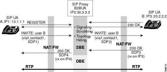
Figure 1 illustrates the data path for support of firewall traversal and NAT with the SBC.
Figure 1 Firewall Traversal and NAT
Implementing Firewall Traversal and NAT
This task implements firewall traversal and configures the SBC to assume that all endpoints of the adjacency are behind a NAT device.
SUMMARY STEPS
Note ![]() If the adjacency was previously attached, the no attach command must be issued before modifying the adjacency.
If the adjacency was previously attached, the no attach command must be issued before modifying the adjacency.
1. ![]() configure
configure
2. ![]() sbc service-name
sbc service-name
3. ![]() sbe
sbe
4. ![]() adjacency sip adjacency-name
adjacency sip adjacency-name
5. ![]() nat force-on
nat force-on
6. ![]() signaling-address ipv4 ipv4_IP_address
signaling-address ipv4 ipv4_IP_address
7. ![]() signaling-port port_num
signaling-port port_num
8. ![]() remote-address ipv4 ipv4_IP_address/prefix
remote-address ipv4 ipv4_IP_address/prefix
9. ![]() signaling-peer [gk] peer_name
signaling-peer [gk] peer_name
10. ![]() signaling-peer-port port_num
signaling-peer-port port_num
11. ![]() attach
attach
DETAILED STEPS
Configuration Example of Implementing Firewall Traversal and NAT
The following example implements firewall traversal and NAT:
configure
sbc mysbc
sbe
adjacency sip SIP_7301_1
nat force-on
signaling-address ipv4 88.88.121.102
signaling-port 5060
remote-address ipv4 10.10.111.0/24
signaling-peer 10.10.111.41
signaling-peer-port 5060
attach
 Feedback