Cisco IAD2801 Integrated Access Device Hardware Installation Guide
Bias-Free Language
The documentation set for this product strives to use bias-free language. For the purposes of this documentation set, bias-free is defined as language that does not imply discrimination based on age, disability, gender, racial identity, ethnic identity, sexual orientation, socioeconomic status, and intersectionality. Exceptions may be present in the documentation due to language that is hardcoded in the user interfaces of the product software, language used based on RFP documentation, or language that is used by a referenced third-party product. Learn more about how Cisco is using Inclusive Language.
- Updated:
- August 3, 2007
Chapter: Installing and Upgrading Internal Modules
Installing and Upgrading Internal Modules
This document describes how to install or upgrade modules that are located internally within your Cisco IAD2801 series integrated access devices, such as memory modules, packet voice data modules (PVDMs), and power supplies. You need to remove the cover from the router to install or remove any of these items. The document contains the following sections:
Before you perform any of these module replacement procedures, disconnect the power and remove the cover, as described in the "Removing the Chassis Cover" section. After you complete the module replacement procedures, install the chassis cover as described in the "Installing the Chassis Cover" section.
Safety Warnings

Warning ![]() This equipment must be grounded. Never defeat the ground conductor or operate the equipment in the absence of a suitably installed ground conductor. Contact the appropriate electrical inspection authority or an electrician if you are uncertain that suitable grounding is available. Statement 1024
This equipment must be grounded. Never defeat the ground conductor or operate the equipment in the absence of a suitably installed ground conductor. Contact the appropriate electrical inspection authority or an electrician if you are uncertain that suitable grounding is available. Statement 1024
Warning ![]() Only trained and qualified personnel should be allowed to install, replace, or service this equipment. Statement 1030
Only trained and qualified personnel should be allowed to install, replace, or service this equipment. Statement 1030
Warning ![]() Before working on a system that has an on/off switch, turn OFF the power and unplug the power cord. Statement 1
Before working on a system that has an on/off switch, turn OFF the power and unplug the power cord. Statement 1
Warning ![]() Read the installation instructions before connecting the system to the power source. Statement 1004
Read the installation instructions before connecting the system to the power source. Statement 1004
Warning ![]() Before working on equipment that is connected to power lines, remove jewelry (including rings, necklaces, and watches). Metal objects will heat up when connected to power and ground and can cause serious burns or weld the metal object to the terminals. Statement 43
Before working on equipment that is connected to power lines, remove jewelry (including rings, necklaces, and watches). Metal objects will heat up when connected to power and ground and can cause serious burns or weld the metal object to the terminals. Statement 43
Warning ![]() Hazardous network voltages are present in WAN ports regardless of whether power to the unit is OFF or ON. To avoid electric shock, use caution when working near WAN ports. When detaching cables, detach the end away from the unit first. Statement 1026
Hazardous network voltages are present in WAN ports regardless of whether power to the unit is OFF or ON. To avoid electric shock, use caution when working near WAN ports. When detaching cables, detach the end away from the unit first. Statement 1026
Removing the Chassis Cover
Cisco IAD2801 series integrated access devices have a cover that slides off the rear of the chassis.
Removing the Cover from Cisco IAD2801 Series Integrated Access Devices
To remove the cover from a Cisco IAD2801, follow these steps:
Step 1 ![]() Make sure that the router is turned off and is disconnected from the power supply.
Make sure that the router is turned off and is disconnected from the power supply.
Warning ![]() Before opening the unit, disconnect the telephone-network cables to avoid contact with telephone-network voltages. Statement 1041
Before opening the unit, disconnect the telephone-network cables to avoid contact with telephone-network voltages. Statement 1041
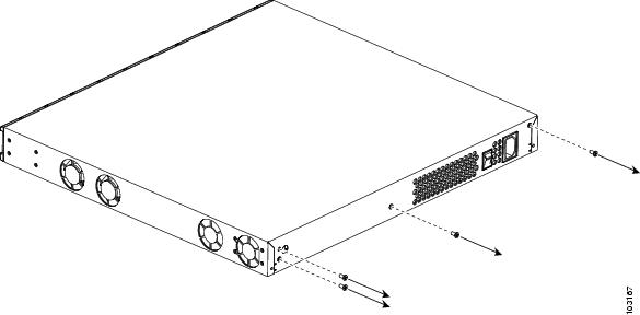
Step 2 ![]() Use a Phillips screwdriver to remove the ground connection screw. Use a flat-blade screwdriver or a hex driver to remove the three screws that hold the chassis and the chassis cover together, as shown in Figure B-1.
Use a Phillips screwdriver to remove the ground connection screw. Use a flat-blade screwdriver or a hex driver to remove the three screws that hold the chassis and the chassis cover together, as shown in Figure B-1.
Figure B-1 Removing the Cisco IAD2801 Chassis Screws
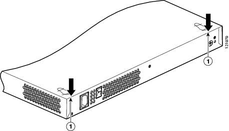
Step 3 ![]() Insert a flat-blade screwdriver between the chassis and chassis cover at the screwdriver pry points on the bottom of the chassis, indicated in Figure B-2. Rotate the screwdriver 90 degrees to disengage the chassis cover from the chassis. It may be necessary to turn the unit upside down on a flat surface to access the pry points.
Insert a flat-blade screwdriver between the chassis and chassis cover at the screwdriver pry points on the bottom of the chassis, indicated in Figure B-2. Rotate the screwdriver 90 degrees to disengage the chassis cover from the chassis. It may be necessary to turn the unit upside down on a flat surface to access the pry points.
Figure B-2 Screwdriver Pry Points
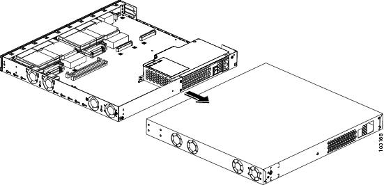
Step 4 ![]() Gently slide the chassis cover of the router away from the bottom of the chassis, as shown in Figure B-3.
Gently slide the chassis cover of the router away from the bottom of the chassis, as shown in Figure B-3.
Figure B-3 Removing the Cisco IAD2801 Chassis Cover
Step 5 ![]() Place the router bottom on an antistatic mat, and begin installing modules.
Place the router bottom on an antistatic mat, and begin installing modules.
Locating Modules
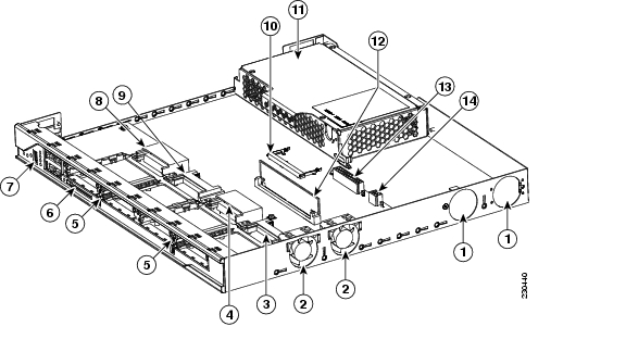
Figure B-4 shows the locations of the DIMMs, PVDMs, and power supply in the Cisco IAD2801.

Note ![]() Advanced integration modules (AIM) are not supported on the Cisco IAD2801.
Advanced integration modules (AIM) are not supported on the Cisco IAD2801.
Figure B-4 Module Locations in Cisco IAD2801 Series Integrated Access Devices
Replacing the Power Supply
To install the main power supply in a Cisco IAD2801, remove the chassis cover as described in the "Removing the Chassis Cover" section, and perform the procedure in the "Installing the Main Power Supply in a Cisco IAD2801" section.

Installing the Main Power Supply in a Cisco IAD2801
To replace the main power supply in a Cisco IAD2801, perform the following steps. See Figure B-4 for the locations of connectors and other components within the Cisco IAD2801.
Step 1 ![]() Disconnect the power supply cable from the main power supply connector.
Disconnect the power supply cable from the main power supply connector.
Step 2 ![]() Remove the screws that fasten the main power supply to the chassis. See Figure B-5.
Remove the screws that fasten the main power supply to the chassis. See Figure B-5.
Figure B-5 Cisco IAD2801 Main Power Supply Removal
.

|
|
Main power supply fastening screws |
|
Main power connector |
|
|
Vent blocking plate fastening screws |
|
Main power supply |
|
|
Vent blocking plate |
Step 3 ![]() Lift the main power supply out of the chassis.
Lift the main power supply out of the chassis.
Step 4 ![]() Install the new power supply.
Install the new power supply.
Step 5 ![]() Connect the main power supply cable to the main power supply connector.
Connect the main power supply cable to the main power supply connector.
Installing the Chassis Cover
Cisco IAD2801 series integrated access devices have a cover that slides onto the chassis from the rear of the chassis. For cover installation procedures, see the "Installing the Cover on Cisco IAD2801 Series Integrated Access Devices" section.
Installing the Cover on Cisco IAD2801 Series Integrated Access Devices
To install the chassis cover on a Cisco IAD2801, follow these steps:
Step 1 ![]() Slide the top cover of the router back on the bottom of the chassis by pushing it in the direction opposite than shown in Figure B-3, "Removing the Cisco IAD2801 Chassis Cover."
Slide the top cover of the router back on the bottom of the chassis by pushing it in the direction opposite than shown in Figure B-3, "Removing the Cisco IAD2801 Chassis Cover."
Step 2 ![]() Replace the three screws and the ground connection that you removed when you opened the chassis. See Figure B-1, "Removing the Cisco IAD2801 Chassis Cover."
Replace the three screws and the ground connection that you removed when you opened the chassis. See Figure B-1, "Removing the Cisco IAD2801 Chassis Cover."
 Feedback