Cisco 815 Cable Router Hardware Installation Guide
Bias-Free Language
The documentation set for this product strives to use bias-free language. For the purposes of this documentation set, bias-free is defined as language that does not imply discrimination based on age, disability, gender, racial identity, ethnic identity, sexual orientation, socioeconomic status, and intersectionality. Exceptions may be present in the documentation due to language that is hardcoded in the user interfaces of the product software, language used based on RFP documentation, or language that is used by a referenced third-party product. Learn more about how Cisco is using Inclusive Language.
- Updated:
- March 20, 2015
Chapter: Installing and Upgrading Memory and Virtual Private Network Modules
Installing and Upgrading Memory and Virtual Private Network Modules
This chapter tells how to install or upgrade memory and how to install a Virtual Private Network (VPN) module in your Cisco 815 integrated services router and includes the following sections:
•![]() Installing and Removing a DIMM
Installing and Removing a DIMM
Safety Warnings

Warning ![]() During this procedure, wear grounding wrist straps to avoid ESD damage to the router. Do not directly touch the backplane with your hand or any metal tool, or you could shock yourself.
During this procedure, wear grounding wrist straps to avoid ESD damage to the router. Do not directly touch the backplane with your hand or any metal tool, or you could shock yourself.
Warning ![]() Before working on a system that has an on/off switch, turn OFF the power and unplug the power cord.
Before working on a system that has an on/off switch, turn OFF the power and unplug the power cord.
Warning ![]() Do not work on the system or connect or disconnect cables during periods of lightning activity.
Do not work on the system or connect or disconnect cables during periods of lightning activity.
Warning ![]() Read the installation instructions before you connect the system to its power source.
Read the installation instructions before you connect the system to its power source.
Warning ![]() Before working on equipment that is connected to power lines, remove jewelry (including rings, necklaces, and watches). Metal objects will heat up when connected to power and ground and can cause serious burns or weld the metal object to the terminals.
Before working on equipment that is connected to power lines, remove jewelry (including rings, necklaces, and watches). Metal objects will heat up when connected to power and ground and can cause serious burns or weld the metal object to the terminals.
Warning ![]() Hazardous network voltages are present in WAN ports regardless of whether power to the router is OFF or ON. To avoid electric shock, use caution when working near WAN ports. When detaching cables, detach the end away from the router first.
Hazardous network voltages are present in WAN ports regardless of whether power to the router is OFF or ON. To avoid electric shock, use caution when working near WAN ports. When detaching cables, detach the end away from the router first.
Opening the Chassis
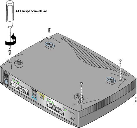
In order to upgrade the Cisco 815 integrated services router memory, you must open the chassis. Opening the chassis requires a number one Phillips screwdriver.
Follow these steps to open the chassis:
Step 1 ![]() Make sure the router is turned off and is disconnected from the power supply.
Make sure the router is turned off and is disconnected from the power supply.
Step 2 ![]() Turn the router upside down, and rest the top of the router on a flat surface.
Turn the router upside down, and rest the top of the router on a flat surface.
Step 3 ![]() Use the number one Phillips screwdriver to remove the four screws that fasten the top and bottom of the chassis together, as shown in Figure C-1.
Use the number one Phillips screwdriver to remove the four screws that fasten the top and bottom of the chassis together, as shown in Figure C-1.
Figure C-1 Removing the Chassis Screws
Step 4 ![]() Holding the router assembly together, turn the router back to its original position.
Holding the router assembly together, turn the router back to its original position.
Step 5 ![]() Gently remove the top of the router (which is facing up toward you) up and away from the bottom of the router (which is resting on the flat surface).
Gently remove the top of the router (which is facing up toward you) up and away from the bottom of the router (which is resting on the flat surface).
At this point, you might have to disconnect the fan, which is inside the top of the router chassis, from the motherboard, by disconnecting the fan cable from the connector (labeled FAN) on the motherboard.
Step 6 ![]() Place the router bottom on an antistatic mat, and begin installing memory.
Place the router bottom on an antistatic mat, and begin installing memory.
Locating Modules
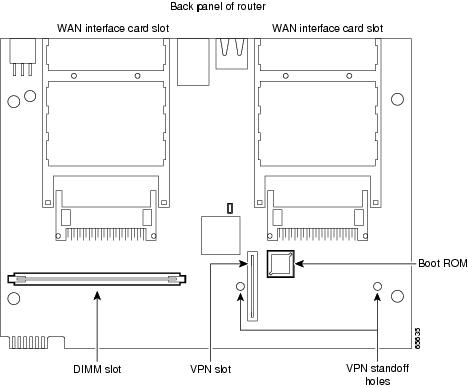
Figure C-2 shows where to find the slots for a dual in-line memory module (DIMM) and a VPN module on the router motherboard.
Figure C-2 Cisco 815 Integrated Services Router Motherboard—Memory Locations
Installing and Removing a DIMM
You can install a DIMM to increase the amount of dynamic random-access memory (DRAM) in the router.
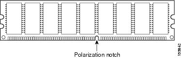
DIMMs have a polarization notch on the mating edge to prevent incorrect insertion. Figure C-3 shows the polarization notch on a DRAM DIMM.
Figure C-3 DIMM Polarization Notch
Removing a DIMM
Follow these steps to remove a DIMM on the router motherboard:
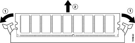
Step 1 ![]() Pull the latches away from the DIMM at both ends. This lifts the DIMM slightly. Lift the DIMM completely out of the connector. See Figure C-4.
Pull the latches away from the DIMM at both ends. This lifts the DIMM slightly. Lift the DIMM completely out of the connector. See Figure C-4.
Figure C-4 Removing a DIMM
|
|
Release the latches |
|
Remove the DIMM |
Step 2 ![]() Place the DIMM in an antistatic bag to protect it from ESD damage.
Place the DIMM in an antistatic bag to protect it from ESD damage.
Installing a DIMM

To install a DIMM, follow these steps:
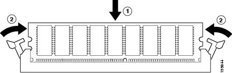
Step 1 ![]() Make sure that both latches on the DIMM connector are open.
Make sure that both latches on the DIMM connector are open.
Step 2 ![]() Orient the DIMM so that the polarization notch lines up with the key in the connector. See Figure C-5.
Orient the DIMM so that the polarization notch lines up with the key in the connector. See Figure C-5.
Step 3 ![]() Carefully insert the DIMM into the connector.
Carefully insert the DIMM into the connector.
Step 4 ![]() Carefully and firmly press the DIMM into the connector until both latches rotate to the closed position against the DIMM.
Carefully and firmly press the DIMM into the connector until both latches rotate to the closed position against the DIMM.
Figure C-5 Installing a DIMM
|
|
Insert the DIMM |
|
Latches rotate to closed position |
Installing a VPN Module
Follow these steps to install a VPN module:
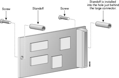
Step 1 ![]() Install the two standoffs on the module, as shown in Figure C-6.
Install the two standoffs on the module, as shown in Figure C-6.
Figure C-6 Installing the Standoffs on the VPN Module
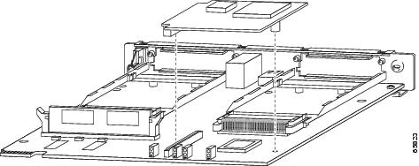
Step 2 ![]() Locate the VPN module slot, and insert the VPN module, as shown in Figure C-7.
Locate the VPN module slot, and insert the VPN module, as shown in Figure C-7.
Figure C-7 VPN Module Location
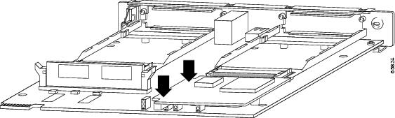
Step 3 ![]() Pushing down as indicated in Figure C-8, plug the VPN module into the slot.
Pushing down as indicated in Figure C-8, plug the VPN module into the slot.
Figure C-8 Seating the VPN Module
Step 4 ![]() To secure the VPN board connection in the socket, you must attach a retention clip.
To secure the VPN board connection in the socket, you must attach a retention clip.
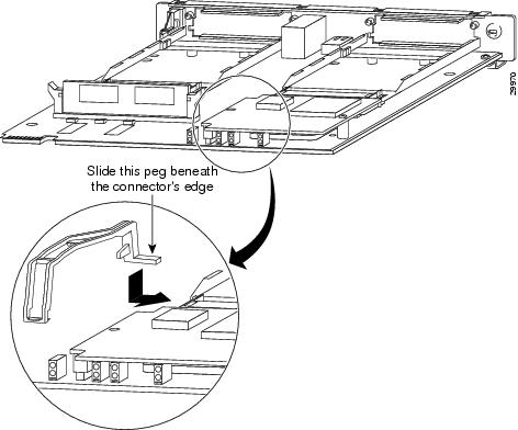
a. ![]() The retention clip for the Cisco 815 integrated services router slides over the VPN module where it connects to the socket and clips to the side of the router motherboard. The horizontal tab slides underneath the WIC 0 socket, as shown in Figure C-9.
The retention clip for the Cisco 815 integrated services router slides over the VPN module where it connects to the socket and clips to the side of the router motherboard. The horizontal tab slides underneath the WIC 0 socket, as shown in Figure C-9.
Figure C-9 Retention Clip Location
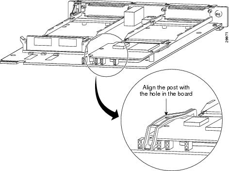
b. ![]() Align the post in the middle of the clip with the hole in the center of the socket side of the VPN card as shown in Figure C-10.
Align the post in the middle of the clip with the hole in the center of the socket side of the VPN card as shown in Figure C-10.
Figure C-10 Aligning the Retention Clip Center Post
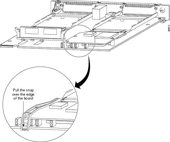
c. ![]() Attach the retention clip to the motherboard, as shown in Figure C-11.
Attach the retention clip to the motherboard, as shown in Figure C-11.
Figure C-11 Attaching the Retention Clip to the Motherboard
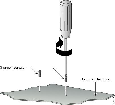
Step 5 ![]() Turn the motherboard over, so that it is resting on its top. Use a Phillips screwdriver to attach the standoffs to the motherboard by using the screws provided, as shown in Figure C-12.
Turn the motherboard over, so that it is resting on its top. Use a Phillips screwdriver to attach the standoffs to the motherboard by using the screws provided, as shown in Figure C-12.
Figure C-12 Securing the Standoff to the Router Motherboard
Closing the Chassis
After installing memory or a VPN module on the motherboard, attach the router cover by following these steps:
Step 1 ![]() If you disconnected the fan from the motherboard in the "Opening the Chassis" procedure, reconnect the fan cable to the connector labeled FAN on the motherboard.
If you disconnected the fan from the motherboard in the "Opening the Chassis" procedure, reconnect the fan cable to the connector labeled FAN on the motherboard.
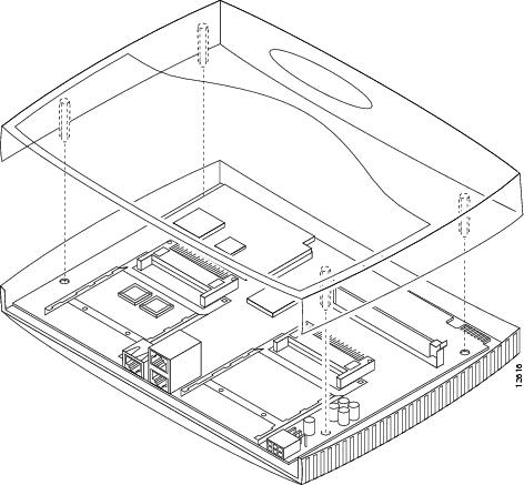
Step 2 ![]() Locate the posts that protrude from the inside of the chassis cover, and locate the corresponding openings on the chassis bottom.
Locate the posts that protrude from the inside of the chassis cover, and locate the corresponding openings on the chassis bottom.
Step 3 ![]() Line up the posts with the corresponding openings, as shown in Figure C-8, and carefully slide the posts into the openings, taking care not to damage the router motherboard with the posts.
Line up the posts with the corresponding openings, as shown in Figure C-8, and carefully slide the posts into the openings, taking care not to damage the router motherboard with the posts.
Figure C-13 Attaching the Router Cover
Step 4 ![]() Using a number one Phillips screwdriver, replace the screws that you removed when you opened the chassis. (See Figure C-1.)
Using a number one Phillips screwdriver, replace the screws that you removed when you opened the chassis. (See Figure C-1.)
 Feedback