Gigabit Interface Converter (GBIC) Module and Small Form-Factor Pluggable (SFP) GBIC Module Install. Info. and Specifications
Available Languages
Table Of Contents
GBIC Module and SFP Module Overview
SFP and GBIC Short Wavelength Modules
SFP and GBIC Long Wavelength Modules
SFP and GBIC Extended Wavelength Modules
GBIC Module and SFP Module Cabling and Connection Equipment
CWDM GBIC Module and SFP Module Description and Information
Mode-Conditioning Patch Cord Description
Installing and Removing the GBIC Module or SFP Module
Removing a GBIC Module or SFP Module
Installing the GBIC Module or SFP Module Interface Cables
Attaching Multimode and Single-Mode Optical Fiber Cables
Attaching the Mode-Conditioning Patch Cord
Fiber-Optic Cleaning Information
Obtaining Documentation and Submitting a Service Request
Gigabit Interface Converter (GBIC) Module and Small Form-Factor Pluggable (SFP) GBIC Module Installation Information and Specifications
GBIC Product Numbers: WS-G5484, WS-G5486, WS-G5487, CWDM-GBIC-1470=, CWDM-GBIC-1490=, CWDM-GBIC-1510=, CWDM-GBIC-1530=, CWDM-GBIC-1550=, CWDM-GBIC-1570=, CWDM-GBIC-1590=, CWDM-GBIC-1610=
SFP Product Numbers: SFP-GE-F=, SFP-GE-S=, SFP-GE-L=, SFP-GE-Z=, GLC-SX-MM=, GLC-LH-SM=, GLC-ZX-SM=, GLC-T=, CWDM-SFP-1470=, CWDM-SFP-1490=, CWDM-SFP-1510=, CWDM-SFP-1530=, CWDM-SFP-1550=, CWDM-SFP-1570=, CWDM-SFP-1590=, CWDM-SFP-1610=.
Revision History Table
The Document Revision History table below, beginning with OL-5007-06, records technical changes to this document.
Introduction
This document provides information about Gigabit Interface Converter (GBIC) modules and small form-factor (SFP) GBIC modules on the Cisco 7200VXR routers, the Cisco 7201 router, the Cisco 7301 router, the Cisco 7304 router, the Cisco 7401ASR router, the Cisco 7500 series routers, the Cisco 7600 series routers, the Cisco 10008 router, the Cisco 12000 series routers, and the Cisco uBR7246VXR cable router and Cisco uBR10012 cable router. The GBIC modules and SFP modules are input/output devices that plug into a Gigabit Ethernet (GE) port, linking the port with a 1000BASE-X fiber-optic network. The devices are used on Cisco platforms that have Gigabit Ethernet interfaces.
Also see the documentation that shipped with the GBIC module or SFP module or the installation guide for your router, I/O controller, processor engine, or port adapter.
Contents
This document contains the following sections:
•
GBIC Module and SFP Module Overview
•
•
•
•
•
•
Related Documentation
The Cisco IOS software running on your router contains extensive features and functionality, which are documented online and in the following resources:
•
http://www.cisco.com/cisco/web/psa/default.html?mode=prodFor hardware installation and maintenance information, refer to the following documents:
•
Cisco 7200 Series Routers Documentation Roadmap
•
Cisco 7201 Router Documentation Roadmap
•
Cisco 7301 Internet Router Documentation Roadmap
Cisco 7304 routerCisco 7304 Internet Router Documentation Roadmap
•
Cisco 7401ASR Router Documentation Roadmap
•
Cisco 7500 Series Routers Documentation Roadmap
•
–
–
•
Cisco 10000 Series Routers Line Card Hardware Installation Guide
Cisco 12000 series routersCisco 12000 Series Internet Router Install and Upgrade Guides
•
–
–
•
–
–
–
–
–
–
–
–
•
GBIC Module and SFP Module Overview
The following topics are in this section:
•
•
•
•
The GBIC module and SFP module are input/output (I/O) devices that plug into a Gigabit Ethernet port, linking the port with a 1000BASE-X fiber-optic network. A GBIC module is shown in Figure 1, and an SFP module in Figure 2.

Note
Figure 1 GBIC Module
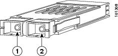
Figure 2 SFP Module
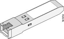
The GBIC module and SFP module have a receiver port (RX) and a transmitter port (TX) that make up one optical interface.
The following tables provide information and specifications:
•
•
•
•
•
Table 2 GBIC Module and SFP Module Transmit Power, Receive Power, and Power Budget
WS-G5484 and GLC-SX-MM
-9.5 dB1
-3 dB1
-17 dB
0 dB
7.5 dB2
WS-G5486 and GLC-LH-SM
-9.5 dB3
-11.5 dB4
-3 dB5
-20 dB
-3 dB
WS-G5487 and
GLC-ZX-SM0 dB
5.2 dB
-24 dB
-3 dB
-24 dB
1 For fiber types 50/125 mm, NA = 0.20 fiber and 62.5/125 mm, NA = 0.275 fiber.
2 For fiber types 50/125 mm MMF and 62.5/125 mm MMF.
3 For fiber types 9/125 mm SMF.
4 For fiber types 62.5/125 mm MMF and 50/125 mm MMF.
5 For fiber types 9/125 mm SMF, 62.5/125 mm MMF, and 50/125 mm MMF.
6 For fiber types 50/125 mm MMF and 62.5/125 mm MMF.
7 For fiber type 10 mm SMF.
Table 3 provides power budget information for the SFP-GE-F, SFP-GE-L, SFP-GE-S, and SFP-GE-Z modules.
Table 3 SFP-GE-F, SFP-GE-L, SFP-GE-S, and SFP-GE-Z Module Transmit Power, Receive Power, and Power Budget
SFP-GE-F=
For 50/125 cabling
For 62.5/125 cabling
-23.5
-20
-14
-14
-33.5
-33.5
-11.8
-11.8
10 dB
13.5 dBSFP-GE-L
-9.5 dB1
-11.5 dB2
-3 dB3
-20 dB
-3 dB
SFP-GE-S
-9.5 dB6
-3 dB
-17 dB
0 dB
7.5 dB7
SFP-GE-Z
0 dB
5 dB
-23 dB
0 dB
-24 dB
1 For fiber types 9/125 mm SMF.
2 For fiber types 62.5/125 mm MMF and 50/125 mm MMF.
3 For fiber types 9/125 mm SMF, 62.5/125 mm MMF, and 50/125 mm MMF.
4 For fiber types 50/125 mm MMF and 62.5/125 mm MMF.
5 For fiber type 10 mm SMF.
6 For fiber types 50/125 mm, NA = 0.20 fiber and 62.5/125 mm, NA = 0.275 fiber.
7 For fiber types 50/125 mm MMF and 62.5/125 mm MMF.
Table 4 lists the GBIC module physical specifications and Table 5 lists the SFP module physical specifications.
SFP and GBIC Short Wavelength Modules
The 1000BASE-SX (short wavelength) GBIC module operates on standard multimode fiber-optic link spans of up to 1804 feet (550 m). (See Table 6.)
The 100BASE-FX SFP module is a hot-swappable device that plugs into a Gigabit Ethernet SFP port. It provides full-duplex 100-Mbps connectivity over multimode fiber (MMF) infrastructures. The 100BASE-FX SFP operates on ordinary MMF optical link spans of up to 1.2428 miles (2 km) in length.
SFP and GBIC Long Wavelength Modules
The 1000BASE-LX/LH (long wavelength/long haul) GBIC module interfaces fully comply with the IEEE 802.3z 1000BASE-LX standard. However, their higher optical quality allows them to reach 6.2 miles (10 km) over single-mode fiber (SMF) versus the 3.1 miles (5 km) specified in the standard.
SFP and GBIC Extended Wavelength Modules
The 1000BASE-ZX (extended wavelength) GBIC module operates on ordinary single-mode fiber-optic link spans of up to 43.5 miles (70 km). Link spans of up to 62.1 miles (100 km) are possible using premium single-mode fiber or dispersion-shifted single-mode fiber (premium single-mode fiber has a lower attenuation per unit length than ordinary single-mode fiber; dispersion-shifted single-mode fiber has both lower attenuation and less dispersion).
The 1000BASE-ZX GBIC module must be coupled to single-mode fiber-optic cable, which is the type of cable typically used in long-haul telecommunications applications. The 1000BASE-ZX GBIC module will not operate correctly when coupled to multimode fiber, and it is not intended to be used in environments where multimode fiber is frequently used (for example, building backbones, or horizontal cabling).
The 1000BASE-ZX GBIC module is intended to be used as a Physical Medium Dependent (PMD) component for Gigabit Ethernet interfaces found on various switch and router products. It operates at a signaling rate of 1250 Mbaud, transmitting and receiving 8B/10B encoded data.
When shorter lengths of single-mode fiber are used, it may be necessary to insert an in-line optical attenuator in the link to avoid overloading the receiver.
•
•
GBIC Module and SFP Module Cabling and Connection Equipment
The GBIC module port is a 1000-Mbps optical interface in the form of an SC-type duplex port (see Figure 1) that supports IEEE 802.3z interfaces compliant with the 1000BASE-X standard.
Table 6 provides cabling specifications for the GBIC modules and SFP modules that you install in Gigabit Ethernet devices. Note that all GBIC module ports have SC-type connectors and all SFP ports have LC-type connectors.
The minimum cable distance for the WS-G5484 or GLC-SX-MM and WS-G5486 or GLC-LH-SM (multimode fiber [MMF] and single-mode fiber [SMF]) is 6.5 feet (2 m), and the minimum link distance for the WS-G5487 or GLC-ZX-SM is 6.2 miles (10 km) with an 8-dB attenuator installed at each end of the link. Without attenuators, the minimum link distance for the WS-G5487 or GLC-ZX-SM is 24.9 miles (40 km).
Table 6 GBIC and SFP Module Port Cabling Specifications
Cable DistanceWS-G5484 or GLC-SX-MM
SFP-GE-S or GLC-SX-MM
850
MMF1
62.5
160
722 ft (220 m)
62.5
200
902 ft (275 m)
50.0
400
1640 ft (500 m)
50.0
500
1804 ft (550 m)
WS-G5486 or GLC-LH-SM
SFP-GE-L or GLC-LH-SM
1300
MMF2 and SMF
62.5
500
1804 ft (550 m)
50.0
400
1804 ft (550 m)
50.0
500
1804 ft (550 m)
9/10
—
6.2 miles (10 km)
WS-G54873 or GLC-ZX-SM
SFP-GE-Z or GLC-ZX-SM
1550
SMF
9/10
—
43.5 miles (70 km)
SMF4
8
—
62.1 miles (100 km)
GLC-GE-100FX
SFP-GE-F
1270 (min),
1300 (avg),
1380 (max)MMF
62.5
62.5
50.0
50.0
500
1.4 miles (6562 ft)
1 Multimode fiber (MMF) only.
2 A mode-conditioning patch cord is required.
When using the WS-G5486 or GLC-LH-SM with 62.5-micron diameter MMF, you must install a mode-conditioning patch cord between the GBIC module or SFP module and the MMF cable on both the transmit and the receive ends of the link when link distances are greater than 984 ft (300 m).
We do not recommend using the WS-G5486 or GLC-LH-SM and MMF with no patch cord for very short link distance (tens of meters). The result could be an elevated bit error rate (BER).3 You can have a maximum of 12 1000BASE-ZX GBIC modules or SFP modules per system to comply with EN55022 Class B and 24 1000BASE-ZX GBIC modules or SFP modules per system to comply with FCC Class A regulations.
4 Dispersion-shifted single-mode fiber-optic cable.
Note
Cisco 1000BASE-T SFP Modules
The 1000BASE-T (GLC-T) SFP module is compliant with IEEE 802.3:2000 and plugs into a standard Gigabit Ethernet SFP module port. It operates on standard Category 5 wiring and has an RJ-45 connector.
See your router installation and configuration guide to determine which routers support the GLC-T SFP module.
CWDM GBIC Module and SFP Module Description and Information
Coarse Wavelength-Division Multiplexing (CWDM) GBIC modules and Coarse Wavelength-Division Multiplexing (CWDM) SFP modules are supported on a variety of Cisco products. For more information, see the Cisco CWDM GBIC Compatibility Matrix and the Cisco Coarse Wavelength-Division Multiplexing SFP Compatibility Matrix.
Figure 3 CWDM GBIC Module
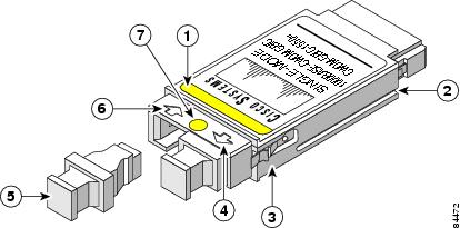
Color band on label
Optical bore dust plug
Alignment groove
Receive optical bore
Spring clip
Color dot
Transmit optical bore
Figure 4 CWDM SFP Module
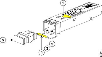
Color arrow on label
Color coded bale clasp
Receive optical bore
Optical bore dust plug
Transmit optical bore
The Cisco CWDM GBIC module and SFP modules enables the transport of up to eight channels (Gigabit Ethernet over single-mode fiber strands. (They also support the transport of up to eight channels [Fiber Channel] over single-mode strands, although Fiber Channel is not discussed in this document.) Cisco CWDM GBIC modules have SC-type connectors, and Cisco CWDM SFP modules have LC-type connectors. They are compatible with 1000BASE-X standard as specified in IEEE 802.3z. The Cisco CWDM GBUC modules and SFP modules are passive and require no power nor configuration. The Cisco CWDM modules support online insertion and removal (OIR).
See your router installation and configuration guide for the Cisco CWDM GBIC modules and SFP modules supported on your router.
The following tables provide specification information:
•
•
•
•
•
•
Parameters are specified over temperature and at end of life unless otherwise noted.
When shorter distances of single-mode fiber are used, it may be necessary to insert an in-line optical attenuator in the link to avoid overloading the receiver.
Parameters are specified over-temperature and at end-of-life unless otherwise noted.
When shorter distances of single-mode fiber are used, it may be necessary to insert an in-line optical attenuator in the link to avoid overloading the receiver.
Mode-Conditioning Patch Cord Description
A mode-conditioning patch cord can be used with the WS-G5486 to allow reliable laser transmission between the single-mode laser source on the GBIC module and a multimode optical fiber cable.
When an unconditioned laser source designed for operation on single-mode optical fiber is directly coupled to a multimode optical fiber cable, an effect known as differential mode delay (DMD) might result in a degradation of the modal bandwidth of the optical fiber cable.
This degradation results in a decrease in the link span (the distance between a transmitter and a receiver) that can be supported reliably. The effect of DMD can be overcome by conditioning the launch characteristics of a laser source. A practical means of performing this conditioning is to use a device called a mode-conditioning patch cord.
A mode-conditioning patch cord is an optical fiber cable assembly that consists of a pair of optical fibers terminated with connector hardware. Specifically, the mode-conditioning patch cord is composed of a single-mode optical fiber permanently coupled off-center (see Offset in Figure 5 and Figure 6) to a graded-index multimode optical fiber. Figure 5 and Figure 6 show a diagram of the mode-conditioning patch cord assembly.
Figure 5 Mode Conditioning Patch Cord Assembly with GBIC Module-Type Connector
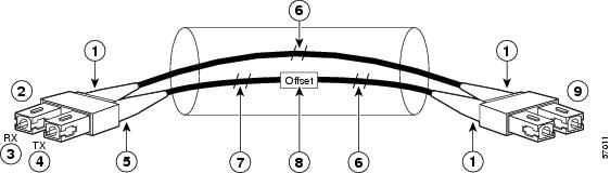
Beige color identifier
Multimode fiber
To GE interface
Single-mode fiber
RX
Offset
TX
To cable plant
Blue color identifier
Figure 6 Mode Conditioning Patch Cord Assembly with SFP Module-Type Connector
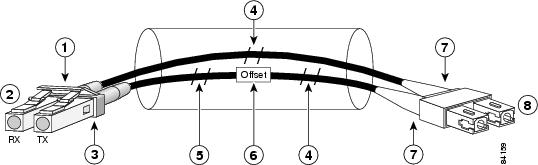
Gray color identifier
Single-mode bar
To GE interface
Offset
Blue color identifier
Beige color identifier
Multimode bar
To cable plant
The mode-conditioning patch cord assembly is composed of duplex optical fibers, including a single-mode-to-multimode offset launch fiber connected to the transmitter, and a second conventional graded-index multimode optical fiber connected to the receiver. The use of a plug-to-plug patch cord maximizes the power budget of multimode 1000BASE-LX and 1000BASE-LH links.
Note
Installation Prerequisites
This section describes safety and compliance guidelines you should observe before you install the GBIC module or SFP module in your Gigabit Ethernet device.
Safety Guidelines
Before handling a GBIC module or SFP module, observe the following guidelines:
•
•
•

Warning
Warning
Warning
FCC Class A Compliance
This equipment has been tested and found to comply with the limits for a Class A digital device, pursuant to part 15 of the FCC rules. These limits are designed to provide reasonable protection against harmful interference when the equipment is operated in a commercial environment. This equipment generates, uses, and can radiate radio-frequency energy and, if not installed and used in accordance with the instruction manual, may cause harmful interference to radio communications. Operation of this equipment in a residential area is likely to cause harmful interference, in which case users will be required to correct the interference at their own expense.
You can determine whether your equipment is causing interference by turning it off. If the interference stops, it was probably caused by the Cisco equipment or one of its peripheral devices. If the equipment causes interference to radio or television reception, try to correct the interference by using one or more of the following measures:
•
•
•
•
Note
Installing and Removing the GBIC Module or SFP Module
GBIC modules or SFP modules might ship already installed in your device, or they might arrive packaged separately. This section describes how to install or remove the GBIC module or SFP module from your Gigabit Ethernet interface.
Note

Caution
Removing a GBIC Module or SFP Module
Warning
Note
To remove a GBIC module, perform the following steps:
Step 1
Step 2
a.
b.
Step 3
This completes the procedure to remove a GBIC module or SFP module from the Gigabit Ethernet interface.
Installing a GBIC Module
Use the following procedure to install a GBIC module:
Note
Step 1
Step 2
Step 3
Note
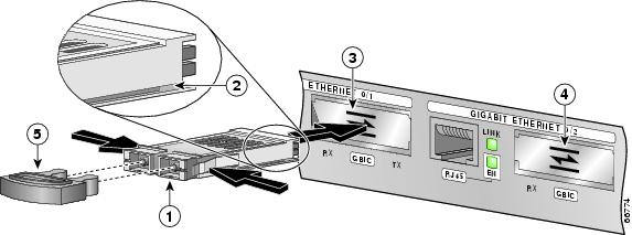
Figure 7 Inserting a GBIC Module with Alignment Groove on Top—Cisco 7301 Gigabit Ethernet Interface Shown
Note
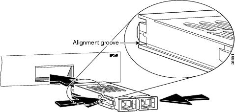
Figure 8 Inserting a GBIC Module with Alignment Groove on the Bottom
Step 4
Step 5
This completes the procedure for installing a GBIC module.
Installing an SFP Module
SFP modules ordered with the system come installed in the system. Optical fiber cables are commercially available; they are not available from Cisco.
Figure 9 Optical SFP Module and Copper SFP Modules
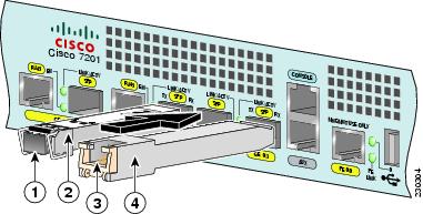
Optical SFP module plug
Copper SFP module RJ-45 connector
Optical SFP module
Copper SFP module
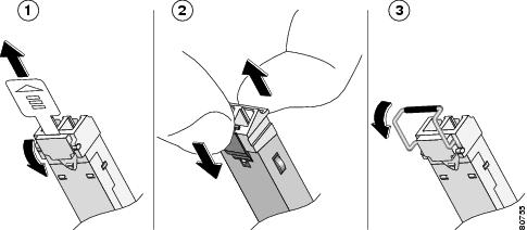
Figure 10 Installing an SFP Module
Step 1
Step 2
Step 3
Figure 11 SFP Module Showing a Variety of Latches
Note
Installing the GBIC Module or SFP Module Interface Cables
This section describes how to attach the interface cables to the GBIC module or SFP module.
Note
Attaching Multimode and Single-Mode Optical Fiber Cables
Attach the appropriate optical fiber cable directly to the SC-type receptacle on the GBIC module or the LC-type connector on the SFP module. You can use either simplex or duplex connectors for most devices. (See Figure 12.)
•
•
Caution
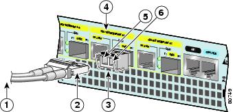
Figure 12 GBIC Module Port Connections
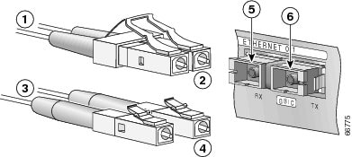
To external 1000BASE-X network
RX
1 duplex connector (RX and TX)
TX
To external 1000BASE-X network
GBIC module port
2 simplex connectors
RJ-45 port
Note
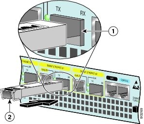
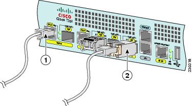
Figure 13 SFP Module Port Connections
To external 1000BASE-X network
SFP (GE) port 0/1
1 duplex connector (RX and TX)
TX
SFP module
RX
Figure 14 RJ-45 Port and Copper SFP RJ-45 Gigabit Ethernet Port Cabling
Attaching the Mode-Conditioning Patch Cord
Perform the following steps to attach the mode-conditioning patch cord:
Step 1
Step 2
Note
If you are attaching cables from CWDM GBIC modules or SFP modules to the Cisco optical add-drop (OADM) modules, see the documentation for the OADM modules.
This completes the procedure for attaching a mode-conditioning patch cord.
Fiber-Optic Cleaning Information
For information about cleaning fiber-optic cable connectors and receptacles, see the Inspection and Cleaning Procedures for Fiber-Optic Connections document. It provides detailed illustrations and photos of procedures and equipment required to properly clean fiber-optic connections. Also see the Compressed Air Cleaning Issues for Fiber-Optic Connections document.
Obtaining Documentation and Submitting a Service Request
For information on obtaining documentation, submitting a service request, and gathering additional information, see the monthly What's New in Cisco Product Documentation, which also lists all new and revised Cisco technical documentation, at:
http://www.cisco.com/en/US/docs/general/whatsnew/whatsnew.html
Subscribe to the What's New in Cisco Product Documentation as a Really Simple Syndication (RSS) feed and set content to be delivered directly to your desktop using a reader application. The RSS feeds are a free service and Cisco currently supports RSS Version 2.0.
Cisco and the Cisco Logo are trademarks of Cisco Systems, Inc. and/or its affiliates in the U.S. and other countries. A listing of Cisco's trademarks can be found at www.cisco.com/go/trademarks. Third party trademarks mentioned are the property of their respective owners. The use of the word partner does not imply a partnership relationship between Cisco and any other company. (1005R)
Copyright © 2009 Cisco Systems, Inc. All rights reserved.
 Feedback
Contact Cisco
- Open a Support Case

- (Requires a Cisco Service Contract)