Cisco NCS 4216 Features
The key feature of the Cisco NCS 4216 is to increase per platform and rack-unit interface density, especially when combining multiple interface types such as Gigabit Ethernet (GE), TDM, 10GE, 40GE, and 100GE.
The Cisco NCS 4216 supports the following RSP modules:
-
NCS4216-RSP: A large service scale and a throughput of 400 Gbps Route Switch Processors (RSP)
-
NCS4216-RSP-800: An extra large service scale and high throughput (800Gbps) Route Switch Processors (RSP)
-
Flexible I/O configurations through multiple pluggable interface modules
For more information about the supported RSP modules and interface modules, refer Table 1 and Table 2.
-
900-Watt PSUs to power the new RSP modules.
The Cisco NCS 4216 includes the following specific components:
-
Chassis—Seven rack unit in height while still maintaining a shallow depth and side-to-side air flow.
-
Fan-tray with removable dust filter
-
Following are the new form factor and high-performance RSP
-
NCS4216-RSP: This high-performance RSP has aggregate switching capacity of 480 Gbps in oversubscribed mode.
-
NCS4216-RSP-800: This high throughput RSP has aggregate switching capacity of 800 Gbps.
-
-
The backplane and the RSP together have the provision to support higher density 10GE modules like 8x10GE and 100GE modules.
-
Air flow baffle to allow a system to redirect air and allow front-to-back airflow for cooling.
-
Flexible I/O configurations through 16 hot pluggable interface modules (single width). For example, with NCS4216-RSP in oversubscribed mode:
-
16x10G + 2x100G + 80x1G
-
48x10G
-
48 T1/E1 TDM Interface Module (48XT1/E1)
-
48 T3/E3 TDM Interface Module (48XT3/E3)
-
OC-192 Interface Module with 8-port Low Rate CEM Interface Module (10G HO / 10G LO)
-
-
Flexible I/O configurations through 16 hot pluggable interface modules (single width). For example, with NCS4216-RSP-800:
-
16x10G + 4x100G + 80x1G
-
48x10G + 4x100G
-
TDM Interface Module and CEM Interface Module are not supported
-
-
Metro ENET switching features along with TDM pseudowire support.
-
Network processor provides flexibility to off-load control plane CPU processing for select OAM and management packets (for example, CCM, BFD, LBM).
-
Flexible ENET processing through table-driven packet processing engines.
-
On-line insertion/removal (OIR) of all FRUs except GPS module, while the system is operational.
-
Power supply (2+1)—Support for DC power supply. Two PSUs should be powered-on at a time. If all the three PSUs are powered on, they work in a load-sharing mode.
-
Fully-redundant system with redundant combined control plane and data plane (excluding interfaces), timing support, power supplies, and fans.
-
Active and standby support of redundant control plane and data plane, and timing
-
Intra-chassis IOS redundancy (requires both RSPs)
-
Stateful-switchover between active and standby RSPs (for protocols supported by IOS).
-
In-service software upgrade (ISSU) supported with same RSPs.
-
Timing support for receipt and distribution of network frequency and time including SyncE, BITS, 1PPS/10MHz I/O, IEEE 1588-2008, and NTP.
-
Support for ENET OAM.
-
T1/E1 and T3/E3 line protection compliant with NEBS GR-1089.
-
Patch Panel for the Interface Modules
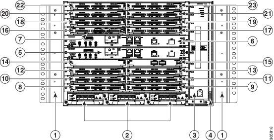
The following figure illustrates the Cisco NCS 4216 chassis design.
|
1 |
Mounting Bracket |
2 |
Redundant power units (three DC power units are shown) |
|
3 |
Fan tray |
4 |
Fan tray filter |
|
5 |
RSP Slot 0 |
6 |
RSP Slot 1 |
|
7 |
IM Carrier plates |
8 |
Slot 0 for Interface Module |
|
9 |
Slot 1 for Interface Module |
10 |
Slot 2 for Interface Module |
|
11 |
Slot 3 for Interface Module |
12 |
Slot 4 for Interface Module |
|
13 |
Slot 5 for Interface Module |
14 |
Slot 6 for Interface Module |
|
15 |
Slot 7 for Interface Module |
16 |
Slot 8 for Interface Module |
|
17 |
Slot 9 for Interface Module |
18 |
Slot 10 for Interface Module |
|
19 |
Slot 11 for Interface Module |
20 |
Slot 12 for Interface Module |
|
21 |
Slot 13 for Interface Module |
22 |
Slot 14 for Interface Module |
|
23 |
Slot 15 for Interface Module |
System Specifications
The following table summarizes the system specifications and environmental requirements for the Cisco NCS 4216.
|
Dimensions (Height x Width x Depth) |
12.224 inches x 17.426 inches x 9.33 inches |
||
|
Dimensions with FRUs |
12.224 inches x 17.426 inches x 10.705 inches
|
||
|
Weight |
|||
|
Chassis with back-plane |
15.868 kg |
||
|
Fan tray |
3.618 kg |
||
|
900W DC PSU |
0.924 kg |
||
|
RSP (NCS4216-RSP) |
2.8 kg |
||
|
Operating Temperature |
The Cisco NCS 4216 supports the following temperature ranges at 1800 m operating altitude:
|
||
|
Nonoperating Temperature |
-40º F to 158º F (-40º C to +70º C) storage temperature |
||
|
Operating Humidity |
5–95% operating non-condensing relative humidity |
||
|
Operating Altitude |
-60 m to 1800 m operating altitude for full operating temperature range; up to 4000 m at up to 40º C. |
||
|
Nonoperating Altitude |
-60 m to 4570 m storage altitude |
||
|
Vibration |
1.0 g from 1.0 to 150 Hz |
||
|
Shock |
30 G half sine 6 ms and 11 ms |
||
|
Nonoperating Vibration |
Random: 1.15 g RMS 3 to 200 Hz, 30 minutes/axis Sine: 10 to 500 Hz at 0.8 G peak / 5 sweep cycles/axis |
||
|
Operating Acoustics |
< 76 dBA at 27ºC as per NEBS standard GR-63 |
GNSS Module (NCS4216-CM-GNSS)
The GNSS module is present on the RSP. It is a pluggable module that allows direct interface with the external antenna.
 Note |
Using a single GPS antenna input for both RSPs requires usage of external splitters. |
 Warning |
To reduce the risk of fire, use only No. 26 AWG or larger telecommunication line cord. Statement 1023 |
Note |
The GNSS module is not hot swappable. |
GNSS Module RF Input Requirements
- The GNSS module requires an
active GPS/GNSS antenna with built-in Low-Noise Amplifier (LNA) for optimal
performance. The antenna LNA amplifies the received satellite signals for two
purposes:
- Compensation of losses on the cable
- Lifting the signal amplitude in the suitable range for the receiver frontend
The Amplification required is 22dB gain + cable/connector loss + Splitter signal loss.
The recommended range of LNA gain (LNA gain minus all cable and connector losses) at the connector of the receiver module is 22dB to 30dB with a minimum of 20dB and a maximum of 35dB.
- GNSS module provides 5V to the active antenna through the same RF input.
- Surge requirement:
GNSS modules have built-in ESD protections on all pins, including the RF-input pin. However, additional surge protection may be required if rooftop antennas are being connected, to meet the regulations and standards for lightning protection in the countries where the end-product is installed.
A lightning protection must be mounted at the place where the antenna cable enters the building. The primary lightning protection must be capable of conducting all potentially dangerous electrical energy to PE (Protective Earth).
Surge arrestors should support DC-pass and suitable for the GPS frequency range (1.575GHz) with low attenuation.
- Antenna Sky visibility:
GPS signals can only be received on a direct line of sight between antenna and satellite. The antenna should see as much as possible from the total sky. For proper timing, minimum of four satellites should be locked.
Note |
The antenna terminal should be earthed at the building entrance in accordance with the ANSI/NFPA 70, the National Electrical Code (NEC), in particular Section 820.93, Grounding of Outer Conductive Shield of a Coaxial Cable. |
Power Supply Features
The Cisco NCS 4216 supports DC power supplies. The DC power supplies support:
- -40 VDC to -72 VDC
The power supplies are hot-swappable. They are enclosed to prevent exposure to high voltages, and therefore, no power cable interlock is required. However, the power supplies are automatically shut down when removed from the chassis. The power supplies are rated to deliver 900W (~75A at +12VDC) to the other FRUs in the system. The DC power supply has dual input feeds.
The following table shows the DC power supply specifications.
|
Part numbers |
A900-PWR900-D2 |
|
Input power specification |
48V, GND, -48V |
|
Minimum input voltage |
-40.0 V |
|
Maximum input voltage |
-72 VDC |
|
Output voltage |
+12 VDC |
|
Wire gauge for DC input power connections |
10 AWG minimum for -48/-60 VDC. Connector accepts 6AWG maximum. |
|
Maximum power output |
900 W |
Note |
For normal operation, only one power feed is sufficient but an alarm is generated if only one power feed is present. You can suppress this alarm using the alarm profile configuration. |
For more information about installing the Cisco NCS 4216 power supplies, see the Installing the Power Supply .
Redundancy
Three power supplies can be plugged in the NCS 4216 chassis that works in the 2+1 redundancy mode. For the normal operation of the chassis, at least two power supplies should be powered on. When all the three power supplies are plugged in, they work in a current sharing mode.
Each power supply has dual feed. It is recommended to connect each power feed to a separate input source.
Dying Gasp
The Cisco NCS 4216 DC power supply does not support the Dying Gasp feature.
Status LEDs
LEDs are also provided on each power supply to indicate the status of the input power and the health of the power supply. For more information about the LEDs on the Cisco NCS 4216, see Troubleshooting section.
The DC Power Supply Specifications table summarizes the input power specifications for the Cisco NCS 4216 DC power supply units.
Fan Tray
The fan tray module supported on the router is:
-
A907-FAN-E (NCS4216-RSP)
-
A907-FAN-H (NCS4216-RSP-800)
The fan tray has:
-
Four dual rotor fans—for the PSU area cooling
-
12 fans (three columns for four fans)—60x60x38mm fans for the RSP and IM area
The fan tray has the following hardware features:
-
It provides side-to-side forced air cooling
-
It provides redundant fans
-
It is field replaceable
-
It contains status LEDs
For more information about air flow guidelines, see Air Flow Guidelines section. For instructions on how to install the fan tray, see Installing the Fan Tray section. For a summary of the LEDs on the fan tray, see LED Summary section.
Fan Tray (A907-FAN-E)
The A907-FAN-E has:
-
Four dual rotor fans—for the PSU area cooling
-
12 fans (three columns for four fans)—60x60x38mm fans for the RSP and interface modules
This fan tray has redundant fans and provides side-to-side forced air cooling. A907-FAN-E is a field replaceable unit (FRU).
The following table describes the fan speed when used with the NCS4216-RSP route processor.
|
No. |
Temperature (℃) at 1800m |
System Fan Speed (% PWM) |
PSU Fan Speed (% PWM) |
|
|---|---|---|---|---|
|
Minimum |
Maximum |
|||
|
1 |
-40 |
-11 |
30 |
30 |
|
2 |
-10 |
15 |
40 |
40 |
|
3 |
16 |
30 |
55 |
55 |
|
4 |
31 |
40 |
80 |
80 |
|
5 |
41 |
50 |
100 |
100 |
Note |
The system considers the temperature of the fan inlet for the appropriate fan speed. |
For information about the installation of the fan tray, see the Installing the Fan Tray section.
Fan Tray (A907-FAN-H)
The A907-FAN-H has:
-
Four dual rotor fans—for the PSU area cooling
-
12 fans (three columns for four fans)—60x60x38mm fans for the RSP and interface modules
This fan tray has redundant fans and provides side-to-side forced air cooling. A907-FAN-H is a field replaceable unit (FRU).
The following table describes the fan speed when used with the NCS4216-RSP-800 route processor.
|
No. |
Temperature (℃) |
System and PSU Fan Speed (% PWM) |
|
|---|---|---|---|
|
Minimum |
Maximum |
||
|
1 |
-40 |
-31 |
20 |
|
2 |
-30 |
-11 |
30 |
|
3 |
-10 |
30 |
45 |
|
4 |
31 |
40 |
65 |
|
5 |
41 |
50 |
85 |
|
6 |
>50 |
100 |
|
Note |
The system considers the temperature of the fan inlet for the appropriate fan speed. |
For information about the installation of the fan tray, see the Installing the Fan Tray section.
Online Insertion and Removal
The Cisco routers, interface modules, FAN-H, and FAN-E are designed to support online insertion and removal (OIR). However, time-to-OIR for FAN-H and FAN-E fan tray is dependent on the temperature of the chassis. At room temperature of up to 30° C, fan tray OIR should be done within two minutes.
Note |
Before replacing the card, you must perform a graceful shutdown of the card to avoid disk corruption. |
|
Ambient Temperature (in Celsius) |
Fan Operation |
Time |
Remarks |
|---|---|---|---|
|
30° |
All fans are working |
2 minutes |
Fans working as expected |
|
40° |
All fans are working |
1 minute 30 seconds |
Fans working as expected |
|
40° |
Single fan failure |
1 minute 30 seconds |
Single fan failure and all other fans running at maximum speed |
Note |
It is not recommended to perform fan tray OIR above the ambient temperature of 40° C. |
The following table describes the parameters for the OIR of the various modules in the router.
Note |
Before replacing the card, you must perform a graceful shutdown of the card to avoid disk corruption. |
|
OIR Module |
Ambient1 |
Fan Speed |
OIR Time |
Comments |
|---|---|---|---|---|
|
Fan Tray2 |
30°C |
100% PWM |
3 mins |
Single Fan Fail, Other Fans running at 100% PWM |
|
40°C |
100% PWM |
1 minute 30 seconds |
||
|
PSU |
40°C |
As per the fan algorithm |
5 mins |
Fans running at normal speed |
|
Interface Module3 |
||||
|
RSP |
Note |
Consecutive IMs insertions, consecutive IMs reload or removal, and subsequent IM re-insertion should be done while waiting at least 180s between the actions. |
Dust Filter (A907-FAN-F)
The dust filter on the fan tray is a quadrafoam 45PPI filter which is 85 percent dust resistant. For installing the fan filter, see Removing and Replacing the Dust Filter section.
Air Plenum (A907-F2B-AIR)
Air Plenum or air baffle assembly is used to change the air flow pattern of the unit. When the router is installed with the plenum, the air flow pattern is changed from side-side to front-back. The air flow front-back pattern provides a rack installation bay with a cool front zone and hot rear zone. For installing the plenum, see Installing the Air Plenum (A907-F2B-AIR) in the Rack section.
Note |
When the air plenum and the fan filter are installed in the chassis, the system operating temperature is 55º C. |
Door
The door provides access to the shelf, and acts as a protective panel.
Front Door
The front door of NCS 4216 provides access to the shelf, and fan-tray assembly.
The front door acts as protective panels. The laser warning label is placed on the rear of the chassis.
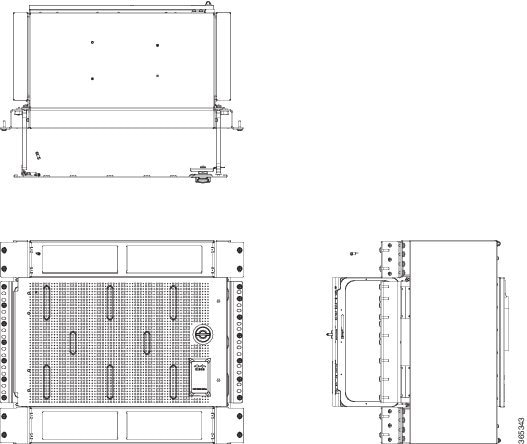
The following figure illustrates the door design showing the front and back of the door.
RSP Modules
The Cisco NCS 4216 is designed to use up to two RSP modules to handle the data plane, network timing, and control plane functionalities for the router. The RSP configuration allows you to use Cisco IOS software to control chassis management, redundancy, external management, and system status indications on the router.
The following sections describe the Cisco NCS 4216 RSP:
- Supported RSP Features
- RSP Redundancy
- Network Timing Interfaces
- RSP Interfaces
RSP features include:
- Loading software onto processor-based interface modules
- Redundant RSP management—The RSP manages detection of RSPs, exchange of health and status information, role negotiation, function for detection, health and status exchange, role negotiation
- Packet processing
- Traffic management, including buffering, queuing, and scheduling, Ethernet MAC functions
- Network clocking functions including phase and time-of-day for BITS, 1 PPS, 10 MHz, and 1588 PTP clock references
- Storage of software images, system configuration, SysLog
- PTP packet processing including IEEE 1588-2008 for recovering network timing (frequency, phase, and time) from upstream PTP clocks, for generating PTP frequency and phase references as inputs to the SETS, and for distributing them to downstream PTP clocks
- External management interfaces (RS232 console, management ENET, USB console, USB storage) and system status LED indicators
Supported RSPs
Cisco NCS 4216 supports the following RSP:
-
NCS4216-RSP—Provides 8 GB of SDRAM, 20 Mb of TCAM memory on every ASIC.
-
NCS4216-RSP-800—Provides 32 GB of CPU DRAM memory.
The RSP does not provide external network interfaces for user traffic. All network interfaces are provided through separate IMs.
Supported RSP Features
The RSP provides the following features on the Cisco router:
-
Centralized data plane, timing, and control plane functions for the system
-
High-level control of interface modules
-
Management functionalities for the router
-
Control plane (host) CPU and associated memory in which Cisco IOS XE and Cisco IOS XR software and platform control software runs
-
Nonvolatile memory for storage of software images, configurations, and system files
-
Enabling and monitoring the health and presence of fan trays, interface modules, and power supplies
-
Field replacement and hot-swap capabilities
Swapping of Interface Modules
The following Ethernet interface modules support swapping on the Cisco NCS4216-RSP module:
Use the hw-module subslot default command before performing a swap of the modules to default the interfaces on the interface module.
-
SFP Combo IM—8-port Gigabit Ethernet (8X1GE) + 1-port 10 Gigabit Ethernet (1X10GE)
-
2-port 40 Gigabit Ethernet Interface Module (2X40GE)
-
8/16-port 1 Gigabit Ethernet (SFP/SFP) + 1-port 10 Gigabit Ethernet (SFP+) / 2-port 1 Gigabit Ethernet (CSFP) Interface Module
-
8-port 10 Gigabit Ethernet Interface Module (8X10GE)
-
1-port 100 Gigabit Ethernet Interface Module (1X100GE)
-
2-port 100 Gigabit Ethernet (QSFP) Interface Module (2X100GE)
Use of hw-module subslot default command is not supported on the following interface modules.
-
1-port OC-192 Interface Module with 8-port Low Rate CEM Interface Module (10G HO / 10G LO)
-
48 T1/E1 TDM Interface Module (48XT1/E1)
-
48 T3/E3 TDM Interface Module (48XT3/E3)
-
1-port OC48/ STM-16 or 4-port OC-12/OC-3 / STM-1/STM-4 + 12-Port T1/E1 + 4-Port T3/E3 CEM Interface Module (NCS4200-3GMS)
-
NCS 4200 Combo 8-Port SFP GE and 1-Port 10 GE 20G Interface Module (NCS 4200-1T8S-20CS)
The following Ethernet interface modules support swapping on the Cisco NCS4216-RSP-800 module:
-
8/16-port 1 Gigabit Ethernet (SFP/SFP) + 1-port 10 Gigabit Ethernet (SFP+) / 2-port 1 Gigabit Ethernet (CSFP) Interface Module
-
8-port 10 Gigabit Ethernet Interface Module (8X10GE)
-
2-port 100 Gigabit Ethernet (QSFP) Interface Module (2X100GE)
Note |
If the license feature service-offload enable command is configured, then the NCS4200-1T8LR-PS IM is not supported in the router for RSP3. |
Note |
There are certain restrictions in using the interface modules on different slots in the chassis. Contact Cisco Sales/Support for the valid combinations. |
|
RSP Module |
Interface Modules |
Part Number |
Slot |
|
|---|---|---|---|---|
|
NCS4216-RSP |
SFP Combo IM—8-port Gigabit Ethernet (8X1GE) + 1-port 10 Gigabit Ethernet (1X10GE) |
NCS4200-1T8LR-PS |
2,5,6,9,10,13,14,15 |
|
|
1-port 100 Gigabit Ethernet Interface Module (1X100GE) |
NCS4200-1H-PK |
7, 8 |
||
|
2-port 100 Gigabit Ethernet (QSFP) Interface Module (2X100GE)4 |
NCS4200-2H-PQ |
7, 8 |
||
|
2-port 40 Gigabit Ethernet QSFP Interface Module (2X40GE) |
NCS4200-2Q-P |
3,4,7,8,11,12 |
||
|
8/16-port 1 Gigabit Ethernet (SFP/SFP) + 1-port 10 Gigabit Ethernet (SFP+) / 2-port 1 Gigabit Ethernet (CSFP) Interface Module |
NCS4200-1T16G-PS |
All slots |
||
|
1-port OC485/ STM-16 or 4-port OC-12/OC-3 / STM-1/STM-4 + 12-port T1/E1 + 4-Port T3/E3 CEM Interface Module |
NCS4200-3GMS |
All slots |
||
|
8-port 10 Gigabit Ethernet Interface Module (8X10GE) |
NCS4200-8T-PS |
3,4,7,8,11,12 |
||
|
1-port OC-192 Interface Module with 8-port Low Rate CEM Interface Module (5G/ 10G HO / 10G LO) |
NCS4200-1T8S-10CS |
3,4,7,8,11,12 (10G mode) 0,1,2,5,6,9,10,13,14,15 (5G mode)
|
||
|
NCS 4200 1-Port OC-192 or 8-Port Low Rate CEM 20G Bandwidth Interface Module |
NCS4200-1T8S-20CS |
3,4,7,8,11,12 (20G mode) 0,1,2,5,6,9,10,13,14,15 (10G mode)
|
||
|
48-port T1/E1 Interface module |
NCS4200-48T1E1-CE |
2,3,4,5,6,7,8,9,10,13,14,15 |
||
|
48-port T3/E3 Interface module |
NCS4200-48T3E3-CE |
2,3,4,5,6,7,8,9,10,13,14,15 |
|
RSP Module |
Interface Modules |
Part Number |
Slot |
|---|---|---|---|
|
NCS4216-RSP-800 |
2-port 100 Gigabit Ethernet (QSFP) Interface Module (2 x 100GE) |
NCS4200-2H-PQ |
6 77, 9 |
|
8-port SFP/8-port CSFP Gigabit Ethernet (8/16 x 1GE) and 1-port 10 Gigabit Ethernet (1 x 10GE) Interface Module |
NCS4200-1T16G-PS |
0, 1, 2, 3, 4, 5, 6, 7, 8, 9, 10, 11, 12, 13, 14 and 15 |
|
|
8-port 10 Gigabit Ethernet Interface Module (8 x 10GE) |
NCS4200-8T-PS |
4,5,7,9,10,11 2,3,12,138 |
RSP Redundancy
The Cisco NCS 4216 chassis includes two RSP slots to allow for redundant RSPs. When the router uses redundant RSPs, one RSP operates in the active mode and the other operates in the hot standby mode. Removal or failure of the active RSP results in an automatic switchover to the standby RSP.
Note |
Interface Module Slot support will vary based on Interface Modules used in other slots. For more information, refer the Configuration Guides for details. |
Network Timing Interfaces
The RSP supports the following network timing interfaces:
-
BITS input/output port—RJ48 jack
-
Wire Wrap Interface Through an Adapter
-
1 PPS input and output—Mini coax connectors
-
2.048 or 10 MHz input and output—Mini coax connectors
-
Time of Day (ToD) or input/output port and 1 PPS input port—Shielded RJ45 jack
Network timing interfaces support redundancy in a redundant RSP configuration. Network timing interfaces on a redundant RSP remain in operation while the RSP is in hot standby mode.
RSP Interfaces
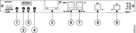
The following figure summarizes the interfaces on the RSP module.
|
Label |
Interface |
|---|---|
|
1 |
1 PPS input timing port |
|
2 |
1 PPS output timing port |
|
3 |
10 MHz input timing port |
|
4 |
10 MHz output timing port |
|
5 |
GNSS RF IN (SMA Threaded Connector) |
|
6 |
USB console port |
|
7 |
USB memory port |
|
8 |
Ethernet management port |
|
9 |
BITS timing port |
Interface Modules
The network interfaces are provided through pluggable interface modules.
The following list describes the various IM port density:
- GE SFP ports—Supports 100/1000 modes
- GE C-SFP ports—Supports 100/1000BASE-BX modes
- 100GE CPAK ports using 1x100G IM
- 100GE QSFP port using 2x100G IM
- 10GE ports through SFP+
- 2X40 GE interface module—Supports QSFP mode
- T1/E1 ports with integrated inter-office surge protection—Supports TDM channelized, PWE3 processing
- T3/E3 ports - Supports TDM channelized, PWE3 Processing
- OC3/OC12/OC48/OC192 - Supports TDM channelized, PWE3 Processing
Note |
For information about supported interface modules, see the data sheet for the Cisco NCS 4200 Series Aggregation Services Routers . |
The Cisco NCS 4216 interface modules are a field-replaceable units. In addition to the ports provided on an RSP, the Cisco NCS 4216 supports the interface modules.
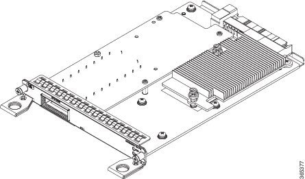
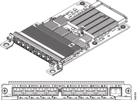
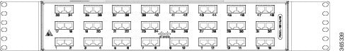
8-port 10 Gigabit Ethernet Interface Module (8X10GE)
The high density 8x10 Gigabit Ethernet interface module supports eight 10 Gigabit Ethernet ports using SFP+ transceivers cages on the faceplate.
Note |
It does not support XFP transceivers on the ports. |
For more information about installing a 8X10GE module, see the Interface Module Installation section.
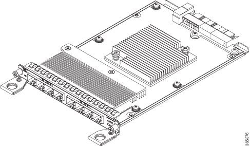
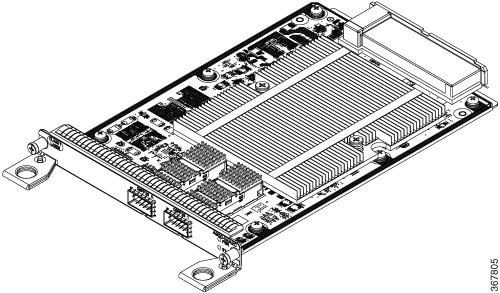
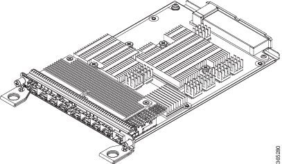
1-port 100 Gigabit Ethernet Interface Module (1X100GE)
The single port 100 Gigabit Ethernet interface module supports100 Gigabit Ethernet port. The figure above shows the interface module.
For more information about installing a 1X100GE module, see the Interface Module Installation section.
2-Port 100 Gigabit Ethernet Interface Module (2X100GE)
The 2-port 100 Gigabit Ethernet Interface Module (NCS4200-2H-PQ) design supports only one 100G QSFP28 optics on Port 0. Port 1 is disabled with RSP3. It currently supports only one mode of operation with 100Gbps of traffic with RSP3.
For more information about installing a 1X100GE module, see the Interface Module Installation section.
Limitations
After any QSFP28 100G optics is inserted, it approximately takes around 10 seconds for the optics to be detected and link to come up. The optics requires this time delay to be complete the initiation and operation.
After inserting the cable or after unshutting the 100G interface, the 100G link may approximately take about 2 seconds to come up.
Note |
QSFP-100G-SR4-S and QSFP-100G-LR4-S are the optics supported in the 2X100GE IM for the 16.10.1 release. |
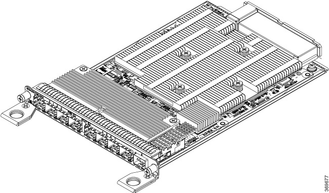
8x1 Gigabit Ethernet SFP+ 1x10 Gigabit Ethernet SFP+ Combination Interface Module
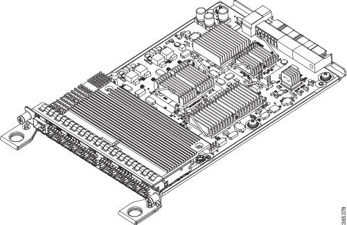
The 8-port 1 Gigabit Ethernet SFP interface module with the 1-port 10 Gigabit Ethernet interface module is a high density combination interface module. This module supports 8 Gigabit Ethernet SFP ports and 1 10 Gigabit Ethernet SFP+ port.
For more information about installing the 8X1 GE SFP + 1X10 SFP Gigabit Ethernet module, see the Interface Module Installation section.
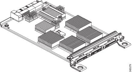
2-port 40 Gigabit Ethernet QSFP Interface Module (2X40GE)
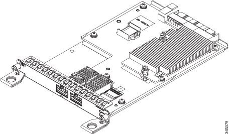
The dual port 40 Gigabit Ethernet interface module supports the 40 Gigabit Ethernet port. The 40G interface is supported using QSFP+ optics. The figure above shows the interface module.
For more information about installing a 2X40 GE module, see the Interface Module Installation section.
8/16-Port 1 Gigabit Ethernet (SFP / SFP) + 1-port 10 Gigabit Ethernet (SFP+) / 2-port 1 Gigabit Ethernet (CSFP) Interface Module
-
1-Port 10 Gigabit Ethernet Small Form-Factor Pluggable (SFP+) interface supports one of three modules as 1xSFP+, 1xSFP or 1xCSFP.
-
8-Port Gigabit Ethernet Small Form-Factor Pluggable (SFP) interface supports as either 8xSFP, or 8xCSFP.
-
8 x 1GigE (SFP) Fully subscribed mode (FS)
-
8 x 1GigE (SFP) + 1 x 10GigE (SFP+) Fully subscribed mode (FS)
-
16 x 1GigE (C-SFP) + 1 x 10GigE (SFP+) Fully subscribed mode (FS)
-
16 or 18 x 1GigE (C-SFP) Oversubscribed mode (OS)
-
16 x 1GigE (C-SFP) + 1 x 10GigE (SFP+) Oversubscribed mode (OS)
-
8 or 9 x 1GigE (SFP) Fully subscribed mode (FS)
-
1 x 10GigE (SFP+) Fully subscribed mode (FS)
For more information about installing a 1xSFP or CSFP and 8xSFP or CSFP, see Installing an Interface Module.
For more information on port numbering, see Configuring 8/16-port 1 Gigabit Ethernet (SFP/SFP) + 1-port 10 Gigabit Ethernet (SFP+) / 2-port 1 Gigabit Ethernet (CSFP) Interface Module chapter of the Cisco NCS 4200 Series Software Configuration Guide, Cisco IOS XE Fuji 16.7.x.
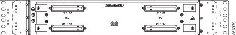
OC-192 Interface Module with 8-port Low Rate CEM Interface Module (10G HO / 10G LO)
The OC-192 interface module with 8-port low rate CEM interface module is a high density combination interface module. This module supports 1 OC-192 port and 8 low rate CEM or 1 Gigabit Ethernet port.
For more information about installing the OC-192 interface module, see the Interface Module Installation section.
NCS 4200 1-Port OC-192 or 8-Port Low Rate CEM 20G Bandwidth Interface Module (NCS4200-1T8S-20CS)
The NCS 4200 1-Port OC-192 or 8-Port Low Rate CEM 20G Bandwidth Interface Module, iMSG is a cost-effective interface module (IM) that supports CEM and Multiservice Gateway features on the OCn interfaces.
Note |
The Multiservice Gateway features are not supported on this IM on Cisco IOS XE Release 16.12.1. |
The NCS 4200 1-Port OC-192 or 8-Port Low Rate CEM 20G Bandwidth Interface Module, iMSG IM supports eight SFP optical interfaces supporting at OC-3/OC-12/OC-48/1G rates and a single SFP+ optical interface supporting at OC-192/10G.
This IM operates in two modes:
-
20G mode; uses two XFI lanes towards the system
-
10G mode; uses single XFI lane towards the system
The benefits of this IM are:
-
Improves backplane efficiency
-
Increases system capacity
-
Increases client flexibility
The most important feature of the NCS 4200 1x10G MR + 8x20G LR CEM, iMSG IM is it provides more flexibility from the interface, which allows you to configure any interface speed on the OCn port irrespective of the IM bandwidth. The bandwidth restriction comes into effect only when the circuit is configured.
For example, you can configure the SFP+ port as an OC-192 and the other eight optical ports as OC-48 to have the total interface speed of 30G. However, if you configure only one STS-1 HO CEP on each port that will take only 9xSTS-1, which is equivalent to 500 Mbps (9 x 52Mbps x1.06) of the backplane traffic.
Restrictions
-
On the port capable of OC-192 speed, lower speed such as, OC-3, OC-12, or OC-48 are not supported.
-
No license is required to enable the Ethernet, OTN and Sonet/SDH functionalities.
-
The SFP port supports OC-3, OC-12, and OC-48. SFP+ port supports OC-192.
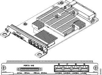
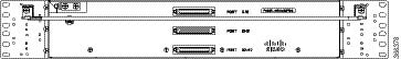
48 X T1/E1 CEM Interface Module
The 48 X T1/E1 interface module provides connectivity for up to 48 x T1/E1 ports through 3 high-density connectors on the front panel. Each port supports 16 TX and RX ports. For information on LEDs, see the Troubleshooting section.

For more information about installing the 48 X T1/E1 interface module, see the Interface Module Installation section.
48 X T3/E3 CEM Interface Module
The 48 X T3/E3 interface module provides connectivity for up to 48 x T3/E3 ports through 3 high-density connectors on the front panel. Each port supports 16 TX and RX ports. For information on LEDs, see the Troubleshooting section.
For more information about installing the 48 X T3/E3 interface module, see the Interface Module Installation section.
1-Port OC48/ STM-16 or 4-port OC-12/OC-3 / STM-1/STM-4 + 12-port T1/E1 + 4-Port T3/E3 CEM Interface Module
-
12xDS1/E1 + 4xDS3/E3/STS-1e interface over the high-density port.
-
1xOC48/12/3 or 1GE interface and 3xOC12/3 or 1GE interface.
Note |
If OC48 is enabled, then the remaining 3 ports are disabled. |
For more information on the supported SFP modules, see the Cisco NCS 4200 Series Network Convergence System Interface Modules Data Sheet.
Temperature Sensor
The Cisco NCS 4216 has a temperature sensor to detect ambient overtemperature conditions inside the chassis. The operating temperature range is between –40 C to +65 C. Temperatures outside this range are reported to the processor as an interrupt, and the software takes action to generate the appropriate alarms.
Patch Panels
The Cisco NCS 4206 has patch panels modules that provide interconnections with the interface modules.
The following table shows different types of patch panel:
|
Patch Panel |
Description |
|---|---|
|
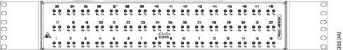
PANEL-48-1-DIN |
48X75 ohm E1/DS1 termination, through DIN 1.0/2.3 connectors |
|
PANEL-48-1-RJ48 |
48X120 ohm E1/110 ohm DS1 termination, through RJ 48C connector |
|
PANEL-48-1-AMP64 |
48X120 ohm E1/110 ohm DS1 termination, through 4xAMP 64-pin |
|
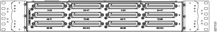
PANEL-144-1-AMP64 |
144X120 ohm E1/110 ohm DS1 termination, through 12XAMP64-pin |
|
Patch Panel |
Description |
|---|---|
|
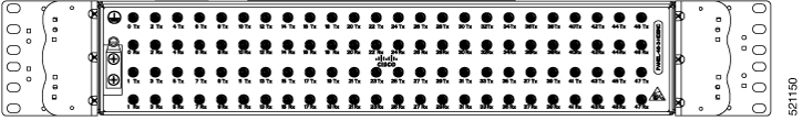
PANEL-48-3-DIN |
48X75 ohm E3/DS3 termination, through DIN 1.0/2.3 connectors |
|
PANEL-48-3-HDBNC |
48X75 ohm E3/DS3 termination, through HDBNC connectors |
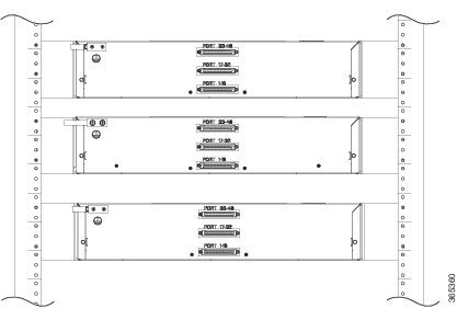
The 48 X T1/E1 TDM interface module and 48 X T3/E3 TDM interface module supports a maximum of 48 TDM ports. These ports are available on the interface modules through three Very-High-Density Cable Interconnect (VHDCI) 16-port connectors. The patch panels listed above make these 48 ports available to the customer via different port densities (48- or 144-port patch panels) with standard Telco connectors (DIN, RJ48, and AMP64 for T1/E1 and DIN, HDBNC for T3/E3).
 Feedback