Overview
This section describes the Cisco Transport Planner, Release 11.1 features, network design process, process flow, traffic planning, traffic services, and parameter states.
Cisco Transport Planner, Release 11.1 Features
Cisco Transport Planner software provides a simple tool set for designing optical networks with Cisco ONS 15454 MSTP and NCS products. You enter all network parameters, or minimal information, such as site distance, and Cisco Transport Planner models the network you need to build and generate a detailed BOM with ordering information. Designing optical networks requires the verification of multiple constraints such, as optical budget limitations and platform architectural restrictions. A single Cisco Transport Planner project can contain multiple copies of a network. This duplication allows you to change parameters in one network copy, and then analyze and compare it with another network copy to study the differences. CTP uses 5us/km for fiber and DCU as a length-based latency.
The new features of Cisco Transport Planner, Release 11.1 are listed in below table:
|
Features |
Description |
|---|---|
|
SMR9 support on SSON |
From Release 11.0, SMR9 with Contentionless Configuration is supported on all SSON Networks. From Release 11.0, Layer2 SMR flag can be enabled on an SSON Network, but no Layer2 Contentionless Side support is present. |
|
Support of Regeneration on Alien |
From Release 11.1 onwards, Regeneration is supported on the NCS 1004 with the Alien NCS4K-4H-OPW-QC2 Line Card and Denali Alien. |
|
Support of RAMAN-COP-CTP on SSON |
From Release 11.1, RAMAN-COP-CTP is supported on SSON Networks. |
|
Support of MER Pluggable on 400G-XP-LC card (OTNXC and MR-MXP mode) |
From Release 11.1, the 400-XP-LC card with MXP and OTNXC mode supports QSFP-4X10-MER pluggable on 10GE, OC192/STM64, OTU2, OTU2e client interfaces. |
|
8GFC Client Interface blocking on CDR ports of 400G-XP-LC card |
From Release 11.0, the 8GFC Blocking is enabled on the CDR ports of the 400G-XP-LC card. |
Important Notes
-
In Release 10.6.1, the TCC2P card can be used only on a standalone Network Element (NE) or as subtended shelf of an MSM having node controller with TCC3 card in M12 or TNCE/TNCS in NCS 2006 or NCS 2015.
-
In Release 10.6.1, an MS-ISC card is not supported in a shelf with a TCC2P card.
 Note |
From R10.6.2 onwards, TCC2P card is no longer supported on M12 Chassis |
Network Design Process
To generate a network design, the SE enters the following parameters:
- The topology of the network—ring, linear, or meshed
- The type of equipment used at each site
- The distance separating the sites
- The type of fiber connecting the sites
- Service demands, including the service type, the protection type, and the number of channels between nodes
- The number of network sites
When the network parameters are entered, Cisco Transport Planner finds the best routing, defines the required add/drop filters, places optical amplifiers with dispersion compensation units (DCUs) or tunable dispersion compensation units (TDCU) to fit the user traffic demands at a minimum cost. The TDCU operates only over the C-band. Optimization is performed to meet the boundary conditions. The optimization includes attenuation and amplification.
Finally, Cisco Transport Planner generates a BOM, which includes the product codes, the quantities, and pricing information. In addition, it creates other reports, such as a shelf-level view of the configuration, which can be printed. This information helps the SE understand how the shelf is built and helps to avoid confusion and errors during the actual deployment. Within the BOM is the total network cost, which allows a quick comparison of various design options. The total network cost is the cost of the equipment for all of the sites in the designed network.
Network Design Constraints
Cisco Transport Planner searches for the best solution to a designed network using an optimization algorithm.
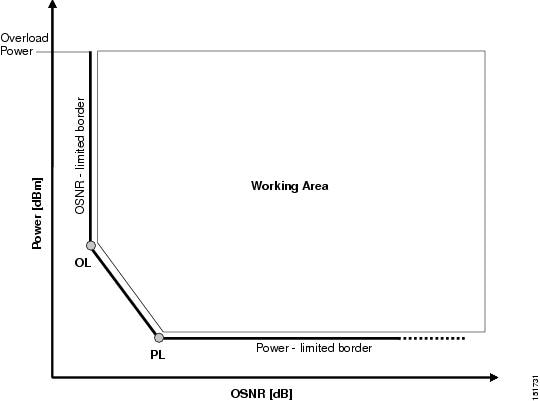
A network design must meet the optical budget and receiver overload criteria to operate efficiently. An analysis of the optical budget and receiver overload evaluates the strength of the signal traversing the ring. If a design solution satisfies the constraints, it is a valid design. The Cisco Transport Planner optimization algorithms generate multiple solutions and verifies the constraints against those solutions. If the constraints are satisfied, the solution with the lowest cost-to-utilization ratio is selected as the optimal solution.
If the network design solution fails to satisfy all the constraints, Cisco Transport Planner makes adjustments to parameters such as signal attenuation and amplification. Amplification is achieved using an erbium-doped fiber amplifier (EDFA). Attenuation is achieved using the variable optical attenuator (VOA) modules integrated into the platform. Cisco Transport Planner corrects the optical budget using an algorithm that includes automatic placement of EDFAs and VOA regulation.
For each internodal demand, Cisco Transport Planner performs an optical budget and receiver overload analysis and displays the results in various reports in the Graphical User Interface (GUI). If the network design algorithms are not able to provide a solution, then you can modify the input data (for example, by relaxing some user constraints) and run the analysis again.
Platform Support
Cisco Transport Planner Software Release 11.1 supports the Cisco ONS 15454 DWDM optical platform Software Releases 9.0, 9.1, 9.2, 9.2.1, 9.3, 9.4, 9.6.0.3, 9.8, 10.0, 10.1, 10.5, 10.5.2, 10.6, 10.6.1, 10.6.2, 10.7, 10.8, 10.9, and 11.0.
Topology Support
The Cisco Transport Planner supports the following network topologies:
- Linear (single-span or multispan)
- Ring (open or closed)
- Meshed
For more information on network topologies, see the Supported Cisco Transport Planner Topologies.
The Cisco Transport Planner enables you to design flexible networks with up to 150 site locations. A flexible network uses ROADM nodes to allow traffic modification or reconfiguration, or both as traffic requirements change.
In Cisco Transport Planner Software R11.1, the maximum number of locations where the optical service channel (OSC) is terminated is 40. The maximum number of add/drop locations supported is 40.
Protection Scheme Support
Cisco Transport Planner designs support the following protection schemes:
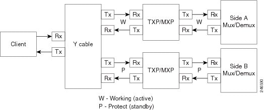
- Y-cable protected—In Y-cable protection, one transponder card is designated as active and the other as standby. The standby transponder card has the client-side laser turned off to avoid corrupting the signal transmitted back to the client. The active transponder monitors the signal from the trunk side and in the event of loss or signal failure, the system switches to the standby path. The following figure shows an example of a Y-cable protected link.
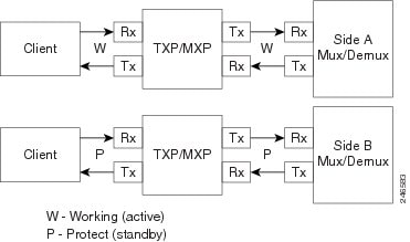
- Client-based 1+1—Two client signals are transmitted to separated line cards or transponder cards instead of using a Y-cable to split one client signal into two line cards or transponder cards. In client 1+1 protection, the failure and switchover is controlled by the client system. The following figure shows an example of a 1+1 protected link.
- Fiber-switched protection—The single client signal is injected into the client receive (Rx) port. It is then split into two separate signals on the two trunk transmit (Tx) ports. The two signals are transmitted over diverse paths. The far-end card chooses one of the two trunk Rx port signals and injects it into the Tx client port. The following figure shows an example of a fiber-switched protected link.
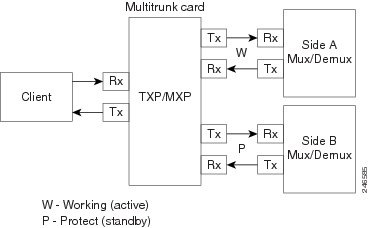
From CTP Release 10.5, fiber-switched protection is supported on a 10x10G-LC card. For more information, see Fiber-Switched Protection on a 10x10G-LC Card.
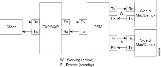
- PSM-OCH—Channel protection configuration provides protection at trunk level (like Fiber-Switched protection) for TXP/MXP that do not have dedicated Fiber-Switched cards. PSM splits the traffic originated by transponder trunk on working and protected TX ports. Working Tx (W-Tx) and protected TX (P-Tx) are connected to the add ports of Add-Drop stages adding the channel in two different directions. On the receiving direction PSM W-RX and P-RX are connected to the drop ports of Add-Drop stages receiving the channel from the two different directions. PSM switch selects a path among W-Rx and P-Rx ports so that only one direction at a time is connected to COM-RX ports and therefore to the TXP/MXP. The following figure shows an example of a PSM-OCH protected link.
From CTP Release 10.5, networks with PSM-OCH protection can be imported into CTP.
From CTP Release 10.8, the 400G-XP-LC card supports trunk based PSM protection (PSM-OCH) on the CFP2 port in Muxponder mode for all the supported trunk rates and service types.
- Unprotected—Protection is not used.
- External card switch—Protection not used.
Fiber-Switched Protection on a 10x10G-LC Card
CTP Release 10.5 supports fiber-switched protection on a 10x10G-LC card. The 10x10G-LC cards support up to two splitter protection groups with one client and two trunk ports:
- First instance: Port 3 (client), Port 4 (Working trunk) and Port 6 (Protect trunk)
- Second instance: Port 7 (client), Port 8 (Working trunk) and Port 10 (Protect trunk)
You can also provision one instance of the fiber-switched protection with port 3 or port 7 as the client port, and up to 3 trunk ports. The operational mode of the card for fiber-switched protection is TXPP-10G. Fiber-switched protection is supported only for 10GE traffic with trunk mode set to Disable (NOFEC), Standard (FEC), or Enhanced (EFEC).
You can configure different wavelengths, threshold crossing alerts (TCAs), alarms threshold, facility and terminal loopbacks on the working and protect trunk ports.
Y-cable protection and fiber-switched protection cannot be configured on the same card.
To configure fiber-switched protection on a 10x10G-LC card, use the following procedure:
When you create a demand, choose Fiber Switched as the protection type from the Protection drop-down list in the Demand Editor dialog box.
Service Support
Cisco Transport Planner can support any subset of the following services:
- Alien (third-party DWDM interface)
- Cisco ONS 15530 2.5 Gbps Aggregated
- ONS 15530 10 Gbps Aggregated
- ONS 15530 Multirate (MR) Transport
- ONS 15530 Data Multiplexer (MXP)
- 2R Any Rate
- 3G-SDI
- Gigabit Ethernet
- 10GE—10 Gigabit Ethernet (LAN and WAN)
- D1 Video
- DVB-ASI—Digital Video Broadcast-Asynchronous Serial Interface
- DV-6000
- DPSK—Different Phase Shift Keying
- ESCON—Enterprise System Connection
- Fast Ethernet
- Fiber Channel 1G
- Fiber Channel 2G
- Fiber Channel 4G
- Fiber Channel 8G
- Fiber Channel 10G
- Fiber Channel 16G
- FICON—Fiber Connection 1G
- FICON Express 2G
- FICON 4G
- FICON 8G
- FICON 10G
- E3 over FE
- T3 over FE
- DS3 over FE
- High Definition Television (HDTV)
- ISC-3 Peer (1G)
- ISC-3 Peer (1G with STP)
- ISC-3 Peer (2G)
- ISC-3 Peer (2G with STP)
- ISC-3 Peer (2R)
- ISC-3 Peer (2R)
- ISC-Compat (ISC-3 Compatibility mode)
- HD-SDI
- HDTV
- OC-3
- OC-12
- OC-48
- OC-192
- OC-768
- OTU2
- SD-SDI
- SDI—Serial Data Input
- STM-1
- STM-4
- STM-16
- STM-64
- STM-256
- 10GE WAN-Phy
- 10GE LAN PHY
- 10GE LANtoWAN
- 100GE
- 40GE LAN PHY
- OTU1
- OTU2
- OTU2e
- OTU3
- OTU4
- Sysplex CLO—control link oscillator
- Sysplex ETR—external throughput rate
- LAN-WAN Conversion
The Sysplex CLO and Sysplex ETR services are supported only on the following topologies:
- Single span—Two terminal sites with 32MUX-O and 32DMX-O cards, 40MUX-O and 40DMX-O cards, 40WSS and 40DMX, or 32WSS and 32DMX or 32DMX-O cards installed and no intermediate sites in between.
- Point-to-Point—Two terminal sites with 32MUX-O and 32DMX-O cards. 40MUX-O and 40DMX-O cards, 40WSS and 40DMX, or 32WSS and 32DMX or 32DMX-O cards installed. Line amplifiers can be installed between the terminal sites, but intermediate (traffic terminating) sites cannot be installed.
- Two hubs—Two hub nodes in a ring with 32MUX-O, 32DMX-O, 32WSS, 40MUX-O, 40DMX, 40DMX-O, 40WSS, and 32DMX cards or 32DMX-O cards installed. Line amplifiers can be installed between the hubs.
For more information about the supported topologies for the ETR and CLO services, refer the Cisco ONS 15454 DWDM Configuration Guide .
The following features are available only when 100GE or OTU4 is selected as the service type during network creation:
- CRS line card 1-100GE-DWDM (FEC, EFEC [default], or HG-FEC) is available for Point-to-Point, P-Ring, and ROADM demands.
- (For Release 9.6.03 and later) MPO-MPO cables are available in the Net view and Site view of the BoM report. MPO-MPO cables are not available for combination cards. For example, MPO-MPO cables are not available if you have chosen 100G-LC-C+CFP-LC or 100G-LC-C+ASR as card type.
The encryption feature is available only:
- When 10GE LAN PHY, OTU2e, OC192, STM64, or OTU2 is selected as the service type during network creation.
- When 100GE is selected with TXP-100G operating mode cards.
-
When 100GE/OTU4 is selected with 400G-XP-LC card
-
When OTN-XC is selected with 400G-XP-LC card.
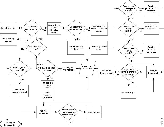
Cisco Transport Planner Process Flow
The following stages are used to complete a network design.
- Create a project using the Project Creation wizard.
- Create a network using the Create Network wizard. The Create Network wizards adds sites and places the fiber spans between the sites. A span represents a pair of fibers.
- Create a point-to-point, Aggregated Ethernet, OTN Aggregated, TDM Aggregated, protected ring (P-ring), and/or ROADM service demand.
- Analyze the network design.
- If you would like to force automatic tool choices, adjust the design and repeat the analysis until you have reached the desired configuration.
- Create an Install copy of the network and update the parameters with real data from the field.
- Analyze the Install network.
- Create an upgrade copy of the network, as needed, to add forecasted channels.
Planning Traffic in Cisco Transport Planner
Traffic in Cisco Transport Planner is defined as an optical path for each pair of nodes requiring a service demand. An optical path is the combined channels between the two nodes. The following list gives definitions for some basic traffic items:
- Circuit—A single channel
between a pair of source and destination nodes. In addition to the source and
destination nodes and all the attributes that are common to the service
containing the circuit, a circuit has the following attributes:
– Present/forecast indication
– Routing direction for unprotected service
– ITU channel
– Optical bypass indication
- Demand—A set of circuits
with common characteristics, such as:
– Service demand label
– Number of existing circuits
– Number of forecasted circuits
– Client service type
– Protection type
– Optical bypass (number of channels and/or sites)
– Present/forecast indication WDM interface type (TXT or ITU-LC)
– WDM card type
– Source client interface (SR, IR, or LR)
– Destination client interface (SR, IR, or LR)
- Traffic demand—All traffic between the same set of nodes. Both L-band and C-band are supported. The following traffic demands
are supported: P-ring, Fixed (point-to-point), and Any-to-any (ROADM).
– In P-ring traffic demands, all the demands are used to support traffic topologies similar to bidirectional line switched rings (BLSRs) or multiplex section-shared protection rings (MS-SPRings). Each P-ring demand is between a pair of added/dropped nodes where BLSR-like (or MS-SPRing-like) traffic must exist. The number of circuits is the same for each demand, and is user-specified (from 1 to 40).
– In fixed (point-to-point) traffic demands, the set of nodes is restricted to two sites. The number of circuits is user-specified (from 1 to 40).
– In any-to-any (ROADM) traffic demands, a minimum of two nodes and a maximum of 40 ROADM nodes are supported. The any-to-any traffic demand allows each node to establish one or more circuits with the other nodes, either as a hub or meshed configuration. In a meshed configuration, each node defined in the set is connected to each of the nodes. This is the most common traffic type. In a hub configuration, the user-defined hub node is connected to each of the other nodes. ROADM circuits have the same protection types and services. The number of circuits is not user-specified and can vary from 0 to 40.
Note
In any-to-any (ROADM) traffic demand, the default routing strategy is Unprotected minimum hop count.
Note
Any-to-Any (ROADM) traffic demand is not supported for SSON networks
A ROADM demand can have multiple client service types and support multiple DWDM card interfaces for each client service type. A ROADM demand supports the following routing strategies:
– Protected (Default)—Each node pair in the traffic demand is connected using two connections.
– Unprotected optimum optical path—Each node pair is connected using one connection. The unprotected optimum optical path minimizes the number of required optical amplifiers, but also restricts the number of channels that can be deployed among the nodes of the traffic demand (maximum of 40 channels between each node pair) in the installed network.
– Unprotected minimum hop count—Each node pair in the traffic demand is connected by one connection. The unprotected minimum hop count maximizes the number of channels (for unprotected traffic types only) that can be deployed among the nodes of the traffic demand, but requires a higher number of optical amplifiers on the unprotected optimum optical path (maximum of 40 channels between each node pair) in the installed network.
– Unprotected subnet—Each node pair in the traffic demand is connected using one connection. You can manually force connections on only one branch of the ring. For unprotected subnets, you must manually select one starting node of the branch and the direction the ring must be traversed to define the subnet, starting from the initial site. The branch direction is specified by defining the outgoing side first, referred to as the starting node. This routing strategy option allows you to exclude some critical paths and (with ROADM traffic demands containing two sites) to force each ROADM connection clockwise or counterclockwise.
Project Explorer Pane
The Project Explorer pane shows all of the open project information, including networks, network dependencies, sites, fibers, services, and so on. The user-defined traffic services are displayed as folders and icons in the Project Explorer pane, as shown in the following figure.
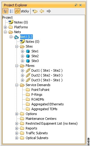
After you analyze a network design, the colors of the icons change according to the error/warning condition of the network design. The icons display in red if there are errors in the network design; orange if there are warnings but no errors; and green if there are no warnings or errors. The icon shows the color of the most severe condition. For more information about analyzing the network, see the Analyzing the Network.
The Project Explorer pane provides the following options to edit the parameters:
- Right-click the folder/icon in the Project Explorer pane to edit the parameters.
- Click sticky to select multiple items in the Project Explorer pane. Edit the properties that are common to the selected items in the Properties pane.
Multiple Selection
Click sticky in the Project Explorer pane toolbar to select multiple folders and icons in the Project Explorer tree or the Network View. Alternatively, hold the Ctrl key on the keyboard and select multiple folders and icons. The folders and icons corresponding to the selection in the Project Explorer pane are highlighted in the Network View and vice-versa. You can also select similar folders and icons by right-clicking them and choosing Select Similar in the menu. For example, by right-clicking a site choosing Select Similar in the menu, you can select all the sites in the Project Explorer pane. The Select Similar option is available only for the folders and icons in the Project Explorer pane that have properties. The properties that are common to the selected items are displayed in the Properties pane. If any property has a different value than the others, that value is highlighted in a different color in the Properties pane.
The following options are available when multiple folders and icons are selected:
- Sites
– Delete, Unlock, and Unlock Pay As You Grow Bundles
– Edit properties
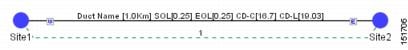
- Ducts
– Delete, Insert Site, and Unlock
– Edit properties
- Service Demands
– Delete and Unlock
– Edit properties
Cisco Transport Planner Traffic in the Project Explorer Pane
Cisco Transport Planner represents all of the user-defined traffic services as folders and icons within the Project Explorer pane.
Point-to-Point Traffic Demands
Point-to-point traffic demands appear in the Service Demands > PointToPoint folder in the Project Explorer pane. Each point-to-point traffic demand is categorized by its source and destination site names. All of the point-to-point services between the two sites appear under the designated demand name.
A point-to-point traffic demand includes the following information:
- Client service type
- Site# – Site# (source and destination site labels for this demand)
P-Ring Traffic Demands
Each protected ring (P-ring) traffic demand appears in the Project Explorer pane under the Service Demands > P-Rings folder.
All the P-ring channels between each site pair are listed under each P-ring traffic demand. Each demand is labeled with the following information:
- P-ring number
- Client service type
- Site# – Site# (source and destination site labels for this demand)
ROADM Traffic Demands
Each ROADM traffic demand appears in the Project Explorer pane under the Service Demands > ROADMs folder. The ROADM folder contains each defined ROADM demand. You can define more demands for the same ROADM for the same set of nodes.
In the Project Explorer pane, each ROADM includes the ROADM demand name and a list of DWDM card types that support the client service types. Protection types appear in parentheses.
Aggregated Ethernet Demand
Each aggregated ethernet traffic demand appears in the Project Explorer pane under the Service Demands > Aggregated Ethernet folder. The Aggregated Ethernet folder contains each defined aggregated ethernet demand. Aggregated Ethernet demands are supported on ring and linear traffic subnets.
TDM Aggregated Demand
Each TDM aggregated demand appears in the Project Explorer pane under the Service Demands > Aggregated TDMs folder.
Note |
TDM aggregated demands are supported only on a ring traffic subnet. |
OTN Aggregated Demand
OTN Aggregated Demand appear in the Service Demands > Aggregated OTN folder in the Project Explorer pane. OTN Aggregated demands are supported on ring and linear traffic subnets.
Note |
ILK Bandwidth can not be used on Terminal node in Linear traffic subnets. Always two interface/sides can be associated with any kind of PRing/ OTN demand. |
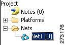
Auto, Forced, and Locked Parameters
Parameters in CTP can be in one of three states:
- Auto— This parameter allows the highest degree of flexibility to CTP in designing a network. When you select Auto, CTP chooses the parameter value during network analysis.
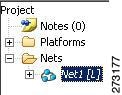
- Forced—When you set a specific parameter value, other than Auto, CTP designs the network using these constraints. When a setting is forced, the item appears in blue italics in the Project Explorer pane.
- Locked—The state of a parameter after network analysis. The next time the analyzer is run, Cisco Transport Planner cannot change the value when it is in the Locked state. You can unlock an item using the Unlock command. For more information, see Unlocking Parameters in the Network Design and Forcing Manager.
Note |
For the WSE card, the encryption option can be modified even when the demand is in locked state. This is available in the Upgrade or Release-upgrade networks and on A2A finalized demands that can be edited from A2A Finalized Circuits. When modifications are made without the unlock, the encryption parameter on the specific port of the WSE card is updated on analysis. |
Depending on the initial state, the network analyzer will:
- Move the parameter into the Locked state if the unit or parameter was set to Auto.
- Leave the parameter in the same state if the user forced a specific value for the unit or parameter.
 Feedback