- Preface
- Cisco ONS Documentation Roadmap for Release 9.6.x
- New and Changed Information
- Chapter 1, Install the Cisco ONS 15454, ONS 15454 M2, and ONS 15454 M6 Shelf
- Chapter 2, Connecting the PC and Logging into the GUI
- Chapter 3, Install the Control Cards
- Chapter 4, Setup Optical Service Channel Cards
- Chapter 5, Optical Amplifier Cards
- Chapter 6, Provision Multiplexer and Demultiplexer Cards
- Chapter 7, Setup Tunable Dispersion Compensating Units
- Chapter 8, Provision Protection Switching Module
- Chapter 9, Optical Add/Drop Cards
- Chapter 10, Reconfigurable Optical Add/Drop Cards
- Chapter 11, Provision Transponder and Muxponder Cards
- Chapter 12, Node Reference
- Chapter 13, Network Reference
- Chapter 14, Turn Up a Node
- Chapter 15, Perform Node Acceptance Tests
- Chapter 16, Turn Up a Network
- Chapter 17, Create Optical Channel Circuits and Provisionable Patchcords
- Chapter 18, Monitor Performance
- Chapter 19, Manage the Node
- Chapter 20, Alarm and TCA Monitoring and Management
- Chapter 21, Change DWDM Card Settings
- Chapter 22, Manage Network Connectivity
- Chapter 23, Upgrade, Add, and Remove Cards and Nodes
- Chapter 24, Maintain the Node
- Chapter 25, Security Reference
- Chapter 26, Timing Reference
- Chapter 27, SNMP
- Appendix A, CTC Operation, Information, and Shortcuts
- Appendix B, Hardware Specifications
- Appendix C, Administrative and Service States
- Appendix D, Configure GE_XP, 10GE_XP, GE_XPE, and 10GE_XPE Cards Using PCLI
- Appendix E, Pseudo Command Line Interface Reference
- Appendix F, Fiber and Connector Losses in Raman Link Configuration
- Appendix G, Card Features
- Appendix H, Network Element Defaults
Cisco ONS 15454 DWDM Configuration Guide, Release 9.6.x
Bias-Free Language
The documentation set for this product strives to use bias-free language. For the purposes of this documentation set, bias-free is defined as language that does not imply discrimination based on age, disability, gender, racial identity, ethnic identity, sexual orientation, socioeconomic status, and intersectionality. Exceptions may be present in the documentation due to language that is hardcoded in the user interfaces of the product software, language used based on RFP documentation, or language that is used by a referenced third-party product. Learn more about how Cisco is using Inclusive Language.
- Updated:
- February 27, 2013
Chapter: Chapter 8, Provision Protection Switching Module
Provision Protection Switching Module
This chapter describes the Protection Switching Module (PSM) card used in Cisco ONS 15454 dense wavelength division multiplexing (DWDM) networks. For card safety and compliance information, refer to the Regulatory Compliance and Safety Information for Cisco CPT and Cisco ONS Platforms document.

Note![]() Unless otherwise specified, “ONS 15454” refers to both ANSI and ETSI shelf assemblies.
Unless otherwise specified, “ONS 15454” refers to both ANSI and ETSI shelf assemblies.
8.1 PSM Card Overview
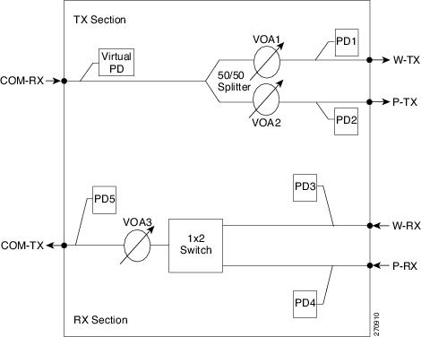
The PSM card performs splitter protection functions. In the transmit (TX) section of the PSM card (see Figure 8-1), the signal received on the common receive port is duplicated by a hardware splitter to both the working and protect transmit ports. In the receive (RX) section of the PSM card (Figure 8-1), a switch is provided to select one of the two input signals (on working and protect receive ports) to be transmitted through the common transmit port.
The PSM card supports multiple protection configurations:
- Channel protection—The PSM COM ports are connected to the TXP/MXP trunk ports.
- Line (or path) protection—The PSM working (W) and protect (P) ports are connected directly to the external line.
- Multiplex section protection—The PSM is equipped between the MUX/DMX stage and the amplification stage.
- Standalone—The PSM can be equipped in any slot and supports all node configurations.
The PSM card is a single-slot card that can be installed in any node from Slot 1 to 6 and 12 to 17. The PSM card includes six LC-PC-II optical connectors on the front panel. In channel protection configuration, the PSM card can be installed in a different shelf from its peer TXP/MXP card.
Note![]() It is strongly recommended that you use the default layouts designed by Cisco Transport Planner, which place the PSM card and its peer TXP/MXP card as close as possible to simplify cable management.
It is strongly recommended that you use the default layouts designed by Cisco Transport Planner, which place the PSM card and its peer TXP/MXP card as close as possible to simplify cable management.
For more information on the node configurations supported for the PSM card, see the Supported Node Configurations for PSM Card.
For more information on the network topologies supported for the PSM card, see the Network Topologies for the PSM Card.
8.1.1 Key Features
The PSM card provides the following features:
- Operates over the C-band (wavelengths from 1529 nm to 1562.5 nm) and L-band (wavelengths from 1570.5 nm to 1604 nm) of the optical spectrum.
- Implements bidirectional non-revertive protection scheme. For more details on bidirectional switching, see the “PSM Bidirectional Switching” section.
- Supports automatic creation of splitter protection group when the PSM card is provisioned.
- Supports switching priorities based on ITU-T G.873.1.
- Supports performance monitoring and alarm handling with settable thresholds.
- Supports automatic laser shutdown (ALS), a safety mechanism used in the event of a fiber cut. ALS is applicable only in line protection configuration. For information about using the card to implement ALS in a network, see the Network Optical Safety.
8.1.2 PSM Block Diagram
Figure 8-1 shows a simplified block diagram of the PSM card.
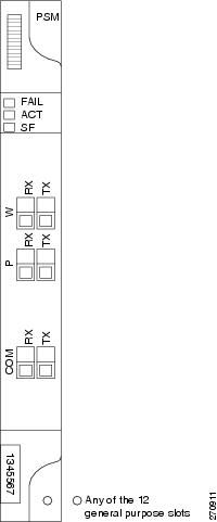
8.1.3 PSM Faceplate Ports
The PSM card has six optical ports located on the faceplate:
- COM-RX (receive) is the input signal port.
- COM-TX (transmit) is the output signal port.
- W-RX is the working input signal port (receive section).
- W-TX is the working output signal port (transmit section).
- P-RX is the protect input signal port (receive section).
- P-TX is the protect output signal port (transmit section).
All ports are equipped with photodiodes to monitor optical power and other related thresholds. The COM-RX port is equipped with a virtual photodiode (firmware calculations of port optical power) to monitor optical power. The W-RX, P-RX, W-TX, and P-TX ports have optical power regulation, which are provided by variable optical attenuators (VOA). All VOAs equipped within the PSM card work in control attenuation mode.
Figure 8-2 shows the PSM card faceplate.
8.1.4 PSM Card-Level Indicators
Table G-1 describes the card-level indicators on the card.
8.1.5 PSM Bidirectional Switching
A VOA is equipped after the hardware splitter within the PSM card. The VOA implements bidirectional switching when there is a single fiber cut in a protection configuration involving two peer PSM cards. Figure 8-3 shows a sample configuration that explains the bidirectional switching capability of the PSM card.
Figure 8-3 PSM Bidirectional Switching
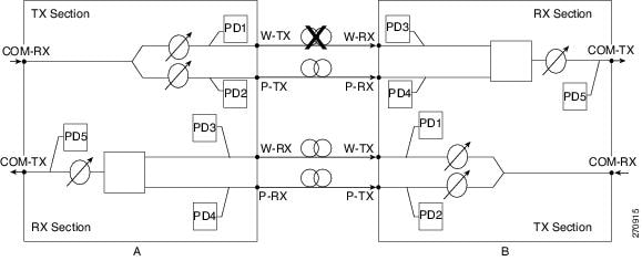
In this example, there is a fiber cut in the working path from Station A to Station B as shown in Figure 8-3. As a result of the fiber cut, an LOS alarm is raised on the W-RX port of Station B and it immediately switches traffic on to its P-RX port. Station B simultaneously also stops transmission (for approximately 25 milliseconds) on its W-TX port, which raises an LOS alarm on the W-RX port of Station A. This causes Station A to also switch traffic to its P-RX port. In this way, PSM implements bidirectional switching without any data exchange between the two stations.
Since the two stations do not communicate using signaling protocols (overhead bytes), a Manual or Force protection switch on the PSM card is implemented by creating a traffic hit. For example, consider that you perform a Manual or Force protection switch on Station A. The TX VOA on the active path is set to automatic VOA shutdown (AVS) state for 25 milliseconds. This causes Station B to switch traffic to the other path because it cannot differentiate between a maintenance operation and a real fail. After 25 milliseconds, the VOA in Station A is automatically reset. However, Station B will not revert back by itself because of nonrevertive switching protection scheme used in the PSM card.
To effectively implement switching, the Lockout and Force commands must be performed on both the stations. If these commands are not performed on both the stations, the far-end and near-end PSMs can be misaligned. In case of misalignment, when a path recovers, traffic might not recover automatically. You might have to perform a Force protection switch to recover traffic.
Note![]() The order in which you repair the paths is important in the event of a double failure (both the working and protect paths are down due to a fiber cut) on the PSM card in line protection configuration when the active path is the working path. If you repair the working path first, traffic is automatically restored. However, if you repair the protect path first, traffic is not automatically restored. You must perform a Force protection switch to restore traffic on the protect path.
The order in which you repair the paths is important in the event of a double failure (both the working and protect paths are down due to a fiber cut) on the PSM card in line protection configuration when the active path is the working path. If you repair the working path first, traffic is automatically restored. However, if you repair the protect path first, traffic is not automatically restored. You must perform a Force protection switch to restore traffic on the protect path.
8.1.6 Related Procedures for PSM Card
The following is the list of procedures and tasks related to the configuration of the PSM card:
- G30 Install the DWDM Cards
- G202 Modify PSM Card Line Settings and PM Thresholds
- G242 Create an Internal Patchcord Manually
- G493 Provision Protected Optical Channel Network Connections
- DLP-G479 View Optical Power Statistics for the PSM Card
- DLP-G176 Modify a Splitter Protection Group
- DLP-G459 Delete a Splitter Protection Group
 Feedback