Cisco Prime Fulfillment Theory of Operations Guide 6.2
Bias-Free Language
The documentation set for this product strives to use bias-free language. For the purposes of this documentation set, bias-free is defined as language that does not imply discrimination based on age, disability, gender, racial identity, ethnic identity, sexual orientation, socioeconomic status, and intersectionality. Exceptions may be present in the documentation due to language that is hardcoded in the user interfaces of the product software, language used based on RFP documentation, or language that is used by a referenced third-party product. Learn more about how Cisco is using Inclusive Language.
- Updated:
- March 20, 2015
Chapter: MPLS-TP Concepts
MPLS-TP Concepts
This chapter includes an overview of Cisco Prime Fulfillment and of some of the concepts used in this guide. This chapter includes the following sections:
•![]() Prime Fulfillment MPLS-TP Overview
Prime Fulfillment MPLS-TP Overview
•![]() Management of MPLS-TP Provisioning
Management of MPLS-TP Provisioning
•![]() Composition of an MPLS-TP Tunnel
Composition of an MPLS-TP Tunnel
Prime Fulfillment MPLS-TP Overview
MPLS-TP is a transport service (managed by Prime Fulfillment) for a dynamic MPLS core (not managed by Prime Fulfillment).
In the current implementation of MPLS-TP, an MPLS-TP tunnel can be provisioned between two arbitrary nodes in an MPLS-TP enabled network. The provisioned tunnel can have one or two paths, a working and an optional protect label-switched path (LSP). The normal use case is for Prime Fulfillment to automatically calculate the working and protect paths using a path selection algorithm that chooses MPLS-TP enabled links based on shortest path, and to provision the tunnel on the endpoints and all nodes traversed by the tunnel.
Figure 6-1 An MPLS-TP Enabled Network
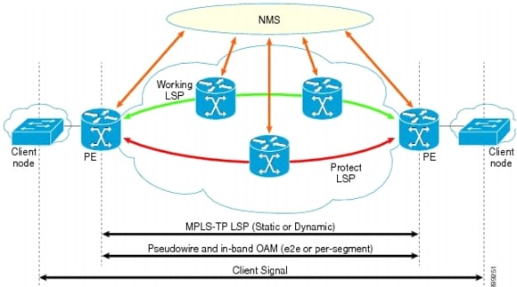
Cisco Prime Provisioning significantly reduces the complexity and time to provision MPLS-TP-based services by discovering MPLS-TP-enabled devices as well as calculating and visually displaying the working and protection paths in the network. The design, path calculation, and the provisioning and audit of MPLS-TP tunnels are provided through a single automated process.
Thefigure below describes how an NMS provisions MPLS-TP tunnels.
Figure 6-2 MPLS-TP Transport Tunnel With Working and Protecting Paths

An MPLS-TP tunnel has two endpoints where the tunnel is configured as a tunnel interface. It has one or two bidirectional label switched path (LSP) pairs between these endpoints. In case of two pairs, one pair is a working path and the second a protection path. The bidirectional LSPs in a pair are congruent, meaning they follow the same path in both directions. This is enforced by the NMS or the optional control plane. The control plane option is not available by default and in its absence, the LSPs are configured at all midpoints. The tunnel can also be configured with bandwidth, however unlike MPLS-TE there is no bandwidth reservation or pre-emption on the network element. The bandwidth number is simply echoed back in show commands; any bandwidth reservation has to be handled within the NMS. BDF can be configured to monitor any of the bidirectional LSP pairs.
The purpose of an MPLS-TP tunnel is to carry pseudowires (PWs). PWs or segments of PWs are explicitly configured to use particular MPLS-TP tunnels using a `pw-class' configuration. The main reason to use MPLS-TP is to have a Packet Oriented Transport System (POTS), which replaces SONET/SDH. The SDH's manageability, predictability, and OAM are replicated as much as possible within a packet transport network. MPLS-TP tunnels do not rely in any way on a working IP control plane. MPLS-TP has only one client network layer, which is pseudowires (PW). Hence the only way to pass traffic through an MPLS-TP tunnel is to configure the MPLS-TP tunnel as the preferred path for the PW.
The function of the transport network is to carry information between service edge devices (for example DSLAM's, Gateways and T1/E1 aggregators). Traditional transport systems based on SONET/SDH platforms provide low-speed bandwidth granularity network services as well as high-speed long-haul transmission services.
Circuit-based transport services with fixed-bandwidth granularity are emulated using connection-oriented packet-switched technologies. In the access/aggregation and metro domains, there is a need to simplify packet transport networking in order to reduce capital expenditure (CapEx) and Operational Expenditure (OpEx) in the networks. Given the deployment of MPLS networks and the need to align packets networking with more traditional transport operations methods, there is a large effort to standardize a simplified version of MPLS for transport networks. This simplified version is known as MPLS Transport Profile (MPLS-TP). MPLS-TP Provisioning operates in the same manner in both Prime Fulfillment Suite and Prime Fulfillment Standalone mode. Some of the common MPLS-TP features are:
•![]() It contains a set of compatible technology enhancements to existing MPLS standards to extend the definition of MPLS to include support for traditional transport operational models.
It contains a set of compatible technology enhancements to existing MPLS standards to extend the definition of MPLS to include support for traditional transport operational models.
•![]() It adopts all of the supporting QoS and other mechanisms already defined in the standards, and additionally brings the benefits of path-based, in-band OAM protection (as found in traditional transport technologies).
It adopts all of the supporting QoS and other mechanisms already defined in the standards, and additionally brings the benefits of path-based, in-band OAM protection (as found in traditional transport technologies).
•![]() Has a set of protocols that are being defined and governed by the Internet Engineering Task Force (IETF). It is a simplified version of MPLS for transport networks with some of the MPLS functions disabled, such as:
Has a set of protocols that are being defined and governed by the Internet Engineering Task Force (IETF). It is a simplified version of MPLS for transport networks with some of the MPLS functions disabled, such as:
–![]() Penultimate hop popping (PHP)
Penultimate hop popping (PHP)
–![]() Label-Switched Paths merge
Label-Switched Paths merge
–![]() Equal Cost Multi-Path (ECMP)
Equal Cost Multi-Path (ECMP)
Figure 6-3 MPLS-TP Tunnel as comprised of LSPs and PWs
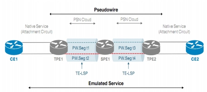
A typical MPLS-TP Tunnel is shown in the figure above. Some of the essential features of MPLS-TP tunnels as defined by the IETF include:
•![]() MPLS forwarding plane with restrictions
MPLS forwarding plane with restrictions
•![]() PWE3 pseudowire Architecture
PWE3 pseudowire Architecture
•![]() Control Plane - static or dynamic G-MPLS
Control Plane - static or dynamic G-MPLS
•![]() Enhanced OAM functionality (vital in the absence of control-plane or routing functions)
Enhanced OAM functionality (vital in the absence of control-plane or routing functions)
•![]() OAM monitors and drives protection switching
OAM monitors and drives protection switching
MPLS-TP Features
Cisco Prime Fulfillment supports the configuration of MPLS-TP tunnels on the Cisco 7600 platform running select IOS versions. It also supports for MPLS-TP Provisioning on the Carrier Packet Transport (CPT) platform with NGXP blade. A dedicated MPLS-TP Discovery tool can be used to discover MPLS-TP topology and resources.
MPLS-TP policies are used to aid the process of provisioning MPLS-TP services. These policies are used when creating MPLS-TP service requests, the mechanism used for configuring the network with MPLS-TP tunnels. Prime Fulfillment's MPLS-TP service uses resource pools to support the automatic allocation of MPLS-TP related resources and to track their usage. See the Cisco Prime Fulfillment User Guide 6.2 for further information about MPLS-TP. This service is also supported through the North-Bound Interface (NBI).
MPLS-TP Control Plane
MPLS-TP does not require MPLS control plane capabilities and enables the management plane (typically via an NMS system) to set up the LSPs manually. Its OAM could operate without any IP layer functionalities (additionally support for IP host and router data plane functionality by MPLS-TP enabled interfaces and networks is optional).
The MPLS-TP Control Plane is the mechanism used to set up an LSP automatically across a packet-switched network domain. However, the use of a control plane in MPLS-TP is optional. Operators can configure the LSPs and PWs using a NMS, and can also perform the following operations:
•![]() Statically configure a PW or LSP without the support of a dynamic control plane.
Statically configure a PW or LSP without the support of a dynamic control plane.
•![]() This can either be by direct configuration of the PEs/LSRs or via an NMS:
This can either be by direct configuration of the PEs/LSRs or via an NMS:
–![]() Static operation is independent for a specific PW or LSP instance.
Static operation is independent for a specific PW or LSP instance.
–![]() Thus, it should be possible for a PW to be statically configured, while the LSP supporting it is set up by a dynamic control plane.
Thus, it should be possible for a PW to be statically configured, while the LSP supporting it is set up by a dynamic control plane.
–![]() When static configuration mechanisms are used, ensure that loops are not created.
When static configuration mechanisms are used, ensure that loops are not created.
Note that the path of an LSP or PW may be dynamically computed, while the LSP or PW itself is established through static configuration.
Management of MPLS-TP Provisioning
In terms of provisioning, SONET/SDH and MPLS-TP provide a similar experience. Often in SDH, there is a management system with a circuit database that has an authoritative store of the network state. Provisioning a new circuit, involves just specifying endpoints. The details are then visible, but you do not need to compute paths, or allocate time-slots (equivalent to labels in MPLS-TP). Some of the common practical issues that can be solved are:
•![]() Simple end-to-end provisioning flows, for end-to-end tunnels.
Simple end-to-end provisioning flows, for end-to-end tunnels.
•![]() Similar open tunnels where the tunnel ends outside the domain controlled by the NMS.
Similar open tunnels where the tunnel ends outside the domain controlled by the NMS.
•![]() Simple provisioning of pseudowires that are the clients of such tunnels.
Simple provisioning of pseudowires that are the clients of such tunnels.
•![]() Provisioning attribute changes on the tunnels, and deletion of tunnels.
Provisioning attribute changes on the tunnels, and deletion of tunnels.
•![]() Configuring path locking, meaning which path of its two redundant paths should a tunnel use.
Configuring path locking, meaning which path of its two redundant paths should a tunnel use.
•![]() Configuring any OAM.
Configuring any OAM.
•![]() Rerouting of tunnels.
Rerouting of tunnels.
•![]() Reapplying configuration in case of lost network node state.
Reapplying configuration in case of lost network node state.
The CLI to create an MPLS-TP is very complex and to create it manually you must:
•![]() Compute two disjoint paths in the topology, determining all midpoints.
Compute two disjoint paths in the topology, determining all midpoints.
•![]() Configure all the midpoints and both endpoints, selecting unique labels at each point, and configuring matching labels at each end of a link.
Configure all the midpoints and both endpoints, selecting unique labels at each point, and configuring matching labels at each end of a link.
•![]() Configure the fields that identify a tunnel at each midpoint, so that OAM works.
Configure the fields that identify a tunnel at each midpoint, so that OAM works.
•![]() Configure OAM at the endpoints.
Configure OAM at the endpoints.
•![]() Test that OAM is verifying the state of the tunnel.
Test that OAM is verifying the state of the tunnel.
The role of Prime Fulfillment in provisioning MPLS-TP includes:
•![]() topology discovery to either compute paths or validate manual path entry
topology discovery to either compute paths or validate manual path entry
•![]() allocation of resources - in this case MPLS labels, tunnel IDs, and bandwidth
allocation of resources - in this case MPLS labels, tunnel IDs, and bandwidth
•![]() activation - i.e. adding configuration to a device
activation - i.e. adding configuration to a device
•![]() validation - ensuring the configuration is accepted and the tunnel is up.
validation - ensuring the configuration is accepted and the tunnel is up.
•![]() service discovery - the discovery of existing MPLS-TP tunnels, including those configured outside of the NMS.
service discovery - the discovery of existing MPLS-TP tunnels, including those configured outside of the NMS.
If you have already invested in a provisioning OSS, and want to invest further in existing OSS, you would require an API. The level of the API might be to create either full or open tunnels by specifying endpoints, or may be an activation API, where the resources and routing are managed by the provisioning component, and the requirement is just for an element manager that activates tunnels.
Composition of an MPLS-TP Tunnel
The key components of a MPLS-TP Tunnel entity are:
•![]() Conventional MPLS Label Switched Paths, which are the "Working LSP" and "Protect LSP" (optional). LSPs that are supported are:
Conventional MPLS Label Switched Paths, which are the "Working LSP" and "Protect LSP" (optional). LSPs that are supported are:
–![]() Point-to-point unidirectional.
Point-to-point unidirectional.
–![]() Point-to-point associated bidirectional. Between LSRs A and B, there exists two unidirectional point-to-point LSPs, one from A to B and one from B to A, which are essentially a pair providing a single logical bidirectional transport path.
Point-to-point associated bidirectional. Between LSRs A and B, there exists two unidirectional point-to-point LSPs, one from A to B and one from B to A, which are essentially a pair providing a single logical bidirectional transport path.
–![]() Point-to-point co-routed bidirectional. This is a point-to-point associated bidirectional LSP with the additional constraint that its two unidirectional component LSPs in each direction follow the same path (in terms of both nodes and links).
Point-to-point co-routed bidirectional. This is a point-to-point associated bidirectional LSP with the additional constraint that its two unidirectional component LSPs in each direction follow the same path (in terms of both nodes and links).
–![]() Point-to-multipoint unidirectional. This functions in the same manner in the data plane, with respect to basic label processing and packet-switching operations as a point-to-point unidirectional LSP, with one difference: an LSR may have more than one (egress interface, outgoing label) pair associated with the LSP, and any packet it transmits on the LSP is transmitted out all associated egress interfaces.
Point-to-multipoint unidirectional. This functions in the same manner in the data plane, with respect to basic label processing and packet-switching operations as a point-to-point unidirectional LSP, with one difference: an LSR may have more than one (egress interface, outgoing label) pair associated with the LSP, and any packet it transmits on the LSP is transmitted out all associated egress interfaces.
•![]() Sections
Sections
•![]() Pseudowires (Single-segment and Multi-segment).
Pseudowires (Single-segment and Multi-segment).
Prime Fulfillment 6.2 supports MPLS-TP tunnels that consist of:
•![]() A working path, where the path is a point-to-point bidirectional transport path.
A working path, where the path is a point-to-point bidirectional transport path.
•![]() An optional protect path, where the path is a point-to-point bidirectional transport path.
An optional protect path, where the path is a point-to-point bidirectional transport path.
•![]() MPLS-TP enabled links.
MPLS-TP enabled links.
MPLS-TP Constructs
•![]() MPLS-TP Provider Edge (PE) Router- an MPLS-TP LSR that adapts client traffic and encapsulates it to be transported over an MPLS-TP LSP. This encapsulation can be as simple as pushing a label, or it could require the use of a pseudowire.
MPLS-TP Provider Edge (PE) Router- an MPLS-TP LSR that adapts client traffic and encapsulates it to be transported over an MPLS-TP LSP. This encapsulation can be as simple as pushing a label, or it could require the use of a pseudowire.
•![]() MPLS-TP Provider (P) Router- an MPLS-TP LSR that does not provide MPLS-TP PE functionality for a given LSP. It switches LSPs that carry client traffic, but does not adapt client traffic and encapsulate it to be carried over an MPLS-TP LSP.
MPLS-TP Provider (P) Router- an MPLS-TP LSR that does not provide MPLS-TP PE functionality for a given LSP. It switches LSPs that carry client traffic, but does not adapt client traffic and encapsulate it to be carried over an MPLS-TP LSP.
•![]() MPLS-TP Transport Layers- an MPLS-TP network logically consists of two layers which are the Transport Service and Transport Path layers.
MPLS-TP Transport Layers- an MPLS-TP network logically consists of two layers which are the Transport Service and Transport Path layers.
–![]() Transport Service layer:
Transport Service layer:
•![]() Provides the interface between Customer Edge (CE) nodes and the MPLS-TP network.
Provides the interface between Customer Edge (CE) nodes and the MPLS-TP network.
•![]() Each packet transmitted by a CE node for transport over the MPLS-TP network is associated at the receiving MPLS-TP Provider Edge (PE) node with a single logical point-to-point connection at the Transport Service layer between this (ingress) PE and the corresponding (egress) PE to which the peer CE is attached.
Each packet transmitted by a CE node for transport over the MPLS-TP network is associated at the receiving MPLS-TP Provider Edge (PE) node with a single logical point-to-point connection at the Transport Service layer between this (ingress) PE and the corresponding (egress) PE to which the peer CE is attached.
•![]() Such a connection is called an MPLS-TP Transport Service Instance, and the set of client packets belonging to the native service associated with such an instance on a particular CE-PE link is called a client flow.
Such a connection is called an MPLS-TP Transport Service Instance, and the set of client packets belonging to the native service associated with such an instance on a particular CE-PE link is called a client flow.
–![]() Transport Path layer:
Transport Path layer:
•![]() Provides aggregation of Transport Service Instances over MPLS-TP transport paths (LSPs), as well as aggregation of transport paths (via LSP hierarchy).
Provides aggregation of Transport Service Instances over MPLS-TP transport paths (LSPs), as well as aggregation of transport paths (via LSP hierarchy).
•![]() Awareness of the Transport Service layer is required only at PE nodes. MPLS-TP Provider (P) nodes need have no awareness of this layer. Both PE and P nodes participate in the Transport Path layer.
Awareness of the Transport Service layer is required only at PE nodes. MPLS-TP Provider (P) nodes need have no awareness of this layer. Both PE and P nodes participate in the Transport Path layer.
•![]() A PE terminates the transport paths it supports, and is responsible for multiplexing and demultiplexing of Transport Service Instance traffic over such transport paths.
A PE terminates the transport paths it supports, and is responsible for multiplexing and demultiplexing of Transport Service Instance traffic over such transport paths.
•![]() MPLS-TP Transport Service Interfaces
MPLS-TP Transport Service Interfaces
–![]() User-Network Interface (UNI) - The UNI for a particular client flow could involve signalling between the CE and PE, and if signalling is used, it could traverse the same attachment circuit that supports the client flow.
User-Network Interface (UNI) - The UNI for a particular client flow could involve signalling between the CE and PE, and if signalling is used, it could traverse the same attachment circuit that supports the client flow.
–![]() Network-Network Interface (NNI) - The NNI for a particular Transport Service Instance may or may not involve signalling between the two PEs. If signalling is used, it may or may not traverse the same data-link that supports the service instance.
Network-Network Interface (NNI) - The NNI for a particular Transport Service Instance may or may not involve signalling between the two PEs. If signalling is used, it may or may not traverse the same data-link that supports the service instance.
 Feedback