Cisco Prime Central 2.0 HA Guide
Bias-Free Language
The documentation set for this product strives to use bias-free language. For the purposes of this documentation set, bias-free is defined as language that does not imply discrimination based on age, disability, gender, racial identity, ethnic identity, sexual orientation, socioeconomic status, and intersectionality. Exceptions may be present in the documentation due to language that is hardcoded in the user interfaces of the product software, language used based on RFP documentation, or language that is used by a referenced third-party product. Learn more about how Cisco is using Inclusive Language.
- Updated:
- July 28, 2017
Chapter: Installing Prime Central in a VMware HA Environment
- Installation Overview
- Installing Prime Central and an Embedded Database in a Local Redundancy HA Configuration
- Before You Begin
- Prime Central HA Setup on RHEL 6.5 or RHEL 6.7 or 6.8
- Adding Clustering to the Installed Red Hat Server (Prime Central)
- Adding Shared Partitions to Prime Central
- Accessing and Distributing the Prime Central.tar File
- Installing Prime Central in an HA Setup
- Setting Up the Prime Central Cluster Service
- Installing the Cluster Web User Interface (luci)
- Setting Up Shared Resources
- Adding Mount Points and Setting Up File Systems
- Adding Scripts to the Prime Central Cluster Service
- Checking the Cluster Services
- Next Steps
- Installing Prime Central Fault Management in a Local Redundancy HA Configuration
- Before You Begin
- Fault Management HA Setup on RHEL 6.5 or RHEL 6.7 or 6.8
- Adding Clustering to the Installed Red Hat Server (Fault Management)
- Configuring Multipath
- Adding Shared Partitions
- Installing Prime Central Fault Management
- Setting Up the Fault Management Cluster Service
- Configuring the Cluster Web User Interface (luci)
- Setting Up Shared Resources
- Adding Mount Points and Setting Up File Systems
- Adding Scripts to the Prime Central Cluster Service
- Checking the Cluster Services
- Troubleshooting
- Upgrading to Prime Central 2.0.0 in a Local Redundancy HA Configuration
- Upgrading to Prime Central Fault Management 2.0 in a Local Redundancy HA Configuration
- Upgrading RHEL Operating System
- Rollback Procedure for Prime Central
- Rollback Procedure for Fault Management
- Uninstalling Prime Central Fault Management
- Uninstalling Prime Central
Setting Up Prime Central High Availability in a VMware or KVM Environment
Installation Overview
The Prime Central RHCS local redundancy HA configuration in a VMware and KVM environment has the following characteristics and requirements:
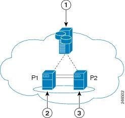
- Prime Central and the embedded database are installed in a dual-node cluster. Figure 2-1 shows a basic dual-node, local redundancy cluster.
- RHCS must be installed on both cluster nodes. Each node has the platform to run both Prime Central and the database services. RHCS manages the local HA setup.
- RHCS requires a disk resource that is mountable from both nodes.
- The Prime Central installer places Prime Central and the database on the node where you ran the installation. After installation, you can relocate them as needed.
- Prime Central and the database services must be placed on the same server.
- Prime Central and the embedded database are always mounted with external shared storage.
- Prime Central does not recognize RHCS. RHCS continuously obtains the cluster status by running a set of scripts. If a problem occurs, RHCS unmounts and then remounts the appropriate server and database. Therefore, every node in the HA setup must be able to mount the storage.
- The Prime Central and oracle home directories must be created manually under the mounted storage. This ensures that the operating system (OS) user created on both servers has a home directory available, even if the storage is moved to another node. These directories must have relevant permissions for the network user and oracle user.
- Each service has its own virtual IP address (virtual IP). This means Prime Central clients treat a failover or switchover like a local service restart.
- Only one instance of the Prime Central files exists, and it is located on the shared storage. Duplicate user and home directories are created on each node as placeholders. If a switchover occurs, the storage unmounts from one node and mounts on the other.
- A local redundancy configuration requires a fencing hardware unit for cutting off a node from the shared storage. Fencing ensures data integrity and prevents a “split-brain scenario” where servers are disconnected from each other, and each assumes the other server failed. If a failure occurs, the cutoff can be performed by:
–![]() Powering off the node with a remote power switch
Powering off the node with a remote power switch
–![]() Disabling a switch port fiber channel
Disabling a switch port fiber channel
–![]() Revoking a host’s SCSI 3 reservations
Revoking a host’s SCSI 3 reservations
If a problem with the cluster node occurs, RHCS invokes the fencing device with the peer and waits for the success signal.
Figure 2-1 Prime Central Dual-Node, Local Redundancy Cluster
|
|
|
||
|
|
|
RHCS Components and Functionality
RHCS is included with the Red Hat Enterprise Linux 6.5, 6.7, or 6.8 (RHEL 6.5, 6.7, or 6.8)Advanced Program and has the following components:
- Cluster infrastructure—Basic functions that enable a group of computers (nodes) to work together as a cluster. The RHCS cluster infrastructure performs cluster management, lock management, fencing, and cluster configuration management.
- High availability service management—Failover of services from one cluster node to another when a node becomes inoperative.
- Cluster administration tools—Configuration and management tools for setting up, configuring, and managing a Red Hat cluster, including cluster infrastructure components, high availability service management components, and storage.
RHCS HA Local Redundancy Requirements
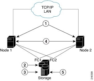
We strongly recommend that you use a hardware installation designed to avoid a single point of failure. See Figure 2-2.
Figure 2-2 Local Redundancy Hardware Installation Designed to Avoid a Single Point of Failure
|
|
|
||
|
|
|
||
|
|
|
Configuring Hardware for Prime Central RHCS Local Redundancy HA
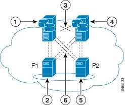
Figure 2-3 shows the recommended hardware configuration for Prime Central RHCS local redundancy HA.
Figure 2-3 Prime Central Dual-Node Cluster for Local Redundancy HA
|
|
|
||
|
|
|
||
|
|
|
Dual connections from each server to each external disk storage unit |
Configure the external storage so all disks and logical unit numbers (LUNs) are accessible from both servers in the cluster. The disk and LUN configuration depends on the storage type:
- If you are using JBOD disks, provide enough physical disks to create the volumes listed in Table 2-2 to satisfy the Oracle performance requirements.
- If you are using storage that supports hardware RAID, divide the physical disks into LUNs so that the volumes listed in Table 2-2 can be created and configured to satisfy the Oracle performance requirements and can be protected with RAID5, RAID1, or RAID10. The Oracle volumes can be created on a single LUN.
|
|
|
|
|---|---|---|
Configuring the OS for Prime Central Local Redundancy HA Managed by RHCS
1.![]() Install the OS and all recommended patches on both servers in the cluster. Installations on both servers must be identical.
Install the OS and all recommended patches on both servers in the cluster. Installations on both servers must be identical.
2.![]() Verify that access is available to all external disks.
Verify that access is available to all external disks.
3.![]() Create the internal disk partitions listed in Table 2-3 . Placing the individual directories in separate partitions is recommended, but not required.
Create the internal disk partitions listed in Table 2-3 . Placing the individual directories in separate partitions is recommended, but not required.
4.![]() Complete the internal disk partitions for both servers.
Complete the internal disk partitions for both servers.
5.![]() Keep the nodes synchronized:
Keep the nodes synchronized:
|
|
|
|---|---|
Standard amount of space + 200 for the cluster configuration |
Installing the Red Hat Cluster Service
Using the procedures in the Red Hat user documentation, install RHEL 5.8/6.5 with the RHCS. When you set up the RHCS disk groups and volumes, keep the following in mind:
Verifying the Prime Central RHCS HA Installation
Installing Prime Central and an Embedded Database in a Local Redundancy HA Configuration
Installing Prime Central in an RHCS local HA configuration is a three-part process:
1.![]() Install RHEL 6.5, 6.7, or 6.8 on both nodes.
Install RHEL 6.5, 6.7, or 6.8 on both nodes.
2.![]() Use multipath shared storage and install Prime Central on node 1.
Use multipath shared storage and install Prime Central on node 1.
3.![]() Configure and enable clustering so that Prime Central can relocate between nodes.
Configure and enable clustering so that Prime Central can relocate between nodes.
The examples provided use the following hostnames and IP addresses; yours will be different:
- Node 1—prime-pc-node1.cisco.com (192.168.1.110)
- Node 2—prime-pc-node2.cisco.com (192.168.1.120)
- Virtual IP address—prime-pc-service.cisco.com (192.168.1.130)
- Gateway—192.168.1.1
- Domain Name System (DNS)—192.168.1.2
- luci—prime-pc-luci.cisco.com (192.168.1.140)
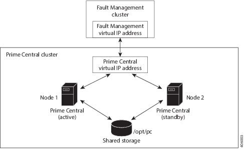
Figure 2-4 shows an example of a Prime Central cluster in an HA configuration.
Figure 2-4 Prime Central Cluster in an HA Configuration
Before You Begin
- Ensure that both PC and FM are installed on different VMs.
- Verify that your system meets all the hardware and software requirements in “Installation Requirements” in the Cisco Prime Central 2.0.0 Quick Start Guide.
- Set up two nodes that have:
–![]() Static IP addresses and hostnames that are registered correctly in the DNS.
Static IP addresses and hostnames that are registered correctly in the DNS.
–![]() The same root password, which cannot contain a percent sign (%, ^, $, *).
The same root password, which cannot contain a percent sign (%, ^, $, *).
- Set up one virtual IP address and hostname that are registered correctly in the DNS. In this section, the virtual IP address is 192.168.1.130.
- Set up shared storage that is compatible with RHEL device-mapper (DM) multipath and cluster fencing.
- Install RHEL 6.5, 6.7, or 6.8 on both nodes.
- If the default folder location and names are changed, look for the section “Require Manual Definition” to make corresponding changes in the below mentioned files:
–![]() /root/ha-stuff/pc/PrimeCentral.sh
/root/ha-stuff/pc/PrimeCentral.sh
Prime Central HA Setup on RHEL 6.5 or RHEL 6.7 or 6.8
Step 1![]() Create three VMs with the configuration specified in the Cisco Prime Central 2.0 Quick Start Guide .
Create three VMs with the configuration specified in the Cisco Prime Central 2.0 Quick Start Guide .
Step 2![]() Install RHEL 6.5 or 6.7 or 6.8 on all three VMs with the Desktop option selected.
Install RHEL 6.5 or 6.7 or 6.8 on all three VMs with the Desktop option selected.
Step 3![]() Disable the firewall on all three VMs:
Disable the firewall on all three VMs:
Step 4![]() On both cluster nodes, switch the network daemons:
On both cluster nodes, switch the network daemons:
Step 5![]() On both cluster nodes, make sure that the nscd RPM package is not installed.
On both cluster nodes, make sure that the nscd RPM package is not installed.
b.![]() Check nscd RPM is installed or not:
Check nscd RPM is installed or not:
c.![]() Enter the following command to uninstall:
Enter the following command to uninstall:
Step 6![]() Disable Security-Enhanced Linux (SELinux) on all three VMs:
Disable Security-Enhanced Linux (SELinux) on all three VMs:
Adding Clustering to the Installed Red Hat Server (Prime Central)
To add clustering to the newly installed Red Hat server, complete Steps 1 through 6 of the following procedure on both cluster nodes and the VM running luci. Then complete Steps 7 through 12 on just the cluster nodes.

Note![]() Below steps are specific for RHEL 6.5 and this procedure is also supported for RHEL 6.7 and 6.8. You have to change the folder names and.iso file names accordingly for RHEL 6.7 and 6.8.
Below steps are specific for RHEL 6.5 and this procedure is also supported for RHEL 6.7 and 6.8. You have to change the folder names and.iso file names accordingly for RHEL 6.7 and 6.8.
Step 1![]() Create local directories named /rhel and /cdrom-6.5.
Create local directories named /rhel and /cdrom-6.5.
Step 2![]() Copy the.iso file that was used for the virtual machine (VM) RHCS installation to the /rhel directory.Mount the /rhel.iso file to /cdrom:
Copy the.iso file that was used for the virtual machine (VM) RHCS installation to the /rhel directory.Mount the /rhel.iso file to /cdrom:
Note![]() To permanently mount the drive, update the /etc/fstab file. See http://docs.redhat.com/docs/en-US/Red_Hat_Enterprise_Linux/4/html/Introduction_To_System_Administration/s2-storage-mount-fstab.html.
To permanently mount the drive, update the /etc/fstab file. See http://docs.redhat.com/docs/en-US/Red_Hat_Enterprise_Linux/4/html/Introduction_To_System_Administration/s2-storage-mount-fstab.html.
Step 3![]() Create a file named /etc/yum.repos.d/local.repo. Use UNIX format and be sure there are no spaces before lines.
Create a file named /etc/yum.repos.d/local.repo. Use UNIX format and be sure there are no spaces before lines.
Step 4![]() Save the newly created file in local.repo, as follows:
Save the newly created file in local.repo, as follows:
Step 5![]() Add the information for both cluster nodes and the VM running luci to the /etc/hosts file; for example:
Add the information for both cluster nodes and the VM running luci to the /etc/hosts file; for example:
Step 6![]() Generate a Secure Shell (SSH) key for the root user:
Generate a Secure Shell (SSH) key for the root user:
Step 7![]() (On the first node only) Share the node’s public key with the other node so that dynamically creating a secure shell between the nodes does not prompt for a password:
(On the first node only) Share the node’s public key with the other node so that dynamically creating a secure shell between the nodes does not prompt for a password:
Step 8![]() Verify that the.ssh directory has 700 permission and the.ssh/id_rsa file has 600 permission:
Verify that the.ssh directory has 700 permission and the.ssh/id_rsa file has 600 permission:
Step 9![]() Verify that your SSH is working without an authentication or password prompt:
Verify that your SSH is working without an authentication or password prompt:

a.![]() On node prime-ha-node1.cisco.com, enter:
On node prime-ha-node1.cisco.com, enter:
b.![]() On node prime-ha-node2.cisco.com, enter:
On node prime-ha-node2.cisco.com, enter:
c.![]() If you are prompted for a password, check the permissions of all folders and files that you modified in the preceding steps.
If you are prompted for a password, check the permissions of all folders and files that you modified in the preceding steps.
d.![]() If you are prompted to continue connecting, enter yes. (The prompt should appear only the first time you use SSH to connect to the node.)
If you are prompted to continue connecting, enter yes. (The prompt should appear only the first time you use SSH to connect to the node.)
Step 10![]() Verify that the virtual IP address is accessible from outside the cluster’s subnet:
Verify that the virtual IP address is accessible from outside the cluster’s subnet:
Step 11![]() On a computer outside the cluster’s subnet, ping the virtual IP address:
On a computer outside the cluster’s subnet, ping the virtual IP address:
If you do not get a valid response, determine which part of the OS or network setup is blocking.
Adding Shared Partitions to Prime Central
To add shared partitions, complete the following steps in parallel on both nodes, except where noted:
Note![]() The examples provided use device mapping names such as mpatha and mpathap1; yours may be different.
The examples provided use device mapping names such as mpatha and mpathap1; yours may be different.
Step 1![]() Install and Set up multipath. Execute the below commands in sequence:
Install and Set up multipath. Execute the below commands in sequence:
Step 2![]() Check for available disks:
Check for available disks:
In the output, note mpath2, which is the multipath virtual device or disk that you will use later as shared storage.
Note![]() If you previously set up a partition on the disk, you might see output such as mpath2p. You must delete that partition before proceeding to the next step.
If you previously set up a partition on the disk, you might see output such as mpath2p. You must delete that partition before proceeding to the next step.
Step 3![]() (On the first node only) Create a shared partition:
(On the first node only) Create a shared partition:
Step 5![]() Check for new partitions:
Check for new partitions:
Step 6![]() (On the first node only) Format the new shared partition:
(On the first node only) Format the new shared partition:
Step 7![]() Create target locations on both nodes:
Create target locations on both nodes:
Step 8![]() Verify that both nodes can mount and unmount the shared storage:
Verify that both nodes can mount and unmount the shared storage:
a.![]() On the first node, mount the shared storage and save a file that contains only the value 1 to the shared storage. The test.txt file should exist in the list of contents of /opt/pc:
On the first node, mount the shared storage and save a file that contains only the value 1 to the shared storage. The test.txt file should exist in the list of contents of /opt/pc:
b.![]() On the second node, mount the shared storage and verify that the test.txt file exists and contains the value 1 :
On the second node, mount the shared storage and verify that the test.txt file exists and contains the value 1 :
If you cannot mount or unmount the shared storage, or if the test.txt file does not exist when you mount it to the second node, your multipath is not set up correctly.
Accessing and Distributing the Prime Central.tar File
Step 1![]() Insert the Cisco Prime Central 2.0.0 USB, navigate to the High Availability/RHCS KVM VMWare ESXi Local HA/Prime Central, and locate the primecentral_v2.0.0_ha_vm.tar.gz file.
Insert the Cisco Prime Central 2.0.0 USB, navigate to the High Availability/RHCS KVM VMWare ESXi Local HA/Prime Central, and locate the primecentral_v2.0.0_ha_vm.tar.gz file.
Step 2![]() Use SSH to connect to the first node.
Use SSH to connect to the first node.
Step 3![]() Copy the primecentral_v2.0.0_ha_vm.tar.gz file to the first node.
Copy the primecentral_v2.0.0_ha_vm.tar.gz file to the first node.
Step 4![]() Back up the following directories on both nodes:
Back up the following directories on both nodes:
Step 5![]() Distribute the file on both nodes:
Distribute the file on both nodes:
Installing Prime Central in an HA Setup
Step 1![]() Mount the shared partitions on first node:
Mount the shared partitions on first node:
Step 2![]() Navigate to the Base Application folder and copy primecentral*.bin and all Oracle zip files to the /root/ha-stuff/pc folder:
Navigate to the Base Application folder and copy primecentral*.bin and all Oracle zip files to the /root/ha-stuff/pc folder:
Step 3![]() Add a virtual IP cluster service address for the Prime Central service:
Add a virtual IP cluster service address for the Prime Central service:
Make sure that virtual IP address is reachable.
Step 4![]() Update the install.properties file (located at /root/ha-stuff/pc) and verify that all required properties have values. Refer to the comments at the top of the install.properties file for details.
Update the install.properties file (located at /root/ha-stuff/pc) and verify that all required properties have values. Refer to the comments at the top of the install.properties file for details.
Step 6![]() In another terminal window, check the installation process:
In another terminal window, check the installation process:
Step 7![]() After the installation completes, start Prime Central:
After the installation completes, start Prime Central:
Step 8![]() Verify that Prime Central is running correctly; then, stop it:
Verify that Prime Central is running correctly; then, stop it:
Step 9![]() Remove the virtual IP addresses:
Remove the virtual IP addresses:
Step 10![]() Unmount the shared partitions:
Unmount the shared partitions:
Setting Up the Prime Central Cluster Service
To set up the Prime Central cluster service, complete the following steps in parallel on all the nodes including luci, except where noted:
Step 1![]() Install the ricci RPMs:
Install the ricci RPMs:
Step 2![]() Start the ricci daemon and configure it to start on boot:
Start the ricci daemon and configure it to start on boot:
Step 3![]() Set the ricci user password:
Set the ricci user password:
You will need to enter this password later.
At this point, both cluster nodes should be running the ricci servers and be ready to be managed by the cluster web user interface (luci).
Installing the Cluster Web User Interface (luci)
Complete the following procedure to install and configure luci on the third VM:.
Step 2![]() Start the luci daemon and configure it to start on boot:
Start the luci daemon and configure it to start on boot:
Step 3![]() Launch the URL listed in the last line of the system output (https://prime-ha-luci.cisco.com:8084, in this example) and log in as the root user when prompted.
Launch the URL listed in the last line of the system output (https://prime-ha-luci.cisco.com:8084, in this example) and log in as the root user when prompted.
Step 4![]() Verify that the RHEL DVD is mounted on both cluster nodes.
Verify that the RHEL DVD is mounted on both cluster nodes.
Step 5![]() Select Manage Clusters > Create and then specify a name for the cluster (for example, PrimePCCluster).
Select Manage Clusters > Create and then specify a name for the cluster (for example, PrimePCCluster).
Step 6![]() Enter the name (fully-qualified domain name or name specified in the /etc/hosts directory) and password (the password for the user ricci) for the first cluster node.
Enter the name (fully-qualified domain name or name specified in the /etc/hosts directory) and password (the password for the user ricci) for the first cluster node.
Step 7![]() Click Add Another Node and enter the same information described in Step 6 for the second cluster node.
Click Add Another Node and enter the same information described in Step 6 for the second cluster node.
Step 8![]() Do the following, and then click Create Cluster:
Do the following, and then click Create Cluster:
Assuming that the nodes can be contacted, luci will set up each cluster node and add each node to the cluster.
After each node has been set up, the High Availability Management screen opens.
Step 9![]() Create a failover domain:
Create a failover domain:
a.![]() Select the Failover Domains tab and then click Add.
Select the Failover Domains tab and then click Add.
–![]() Name: Enter a name for the failover domain.
Name: Enter a name for the failover domain.
–![]() Prioritized: Select this check box.
Prioritized: Select this check box.
–![]() Restricted: Select this check box.
Restricted: Select this check box.
–![]() No Failback: Select this check box.
No Failback: Select this check box.
–![]() Member: Select the check box for each node.
Member: Select the check box for each node.
–![]() Priority. In the Priority column, enter 1 for node1 and 2 for node2.
Priority. In the Priority column, enter 1 for node1 and 2 for node2.
Step 10![]() Configure fence devices appropriate for the hardware you have, adding a fence device and instance for each node.
Configure fence devices appropriate for the hardware you have, adding a fence device and instance for each node.
The settings you need to configure depend on your particular hardware and software configuration. Refer to the Cluster Administration Guide for help with configuring fence devices.
To configure VMware fencing, complete the following steps:
a.![]() Retrieve the UUID for prime-pc-node1.cisco.com:
Retrieve the UUID for prime-pc-node1.cisco.com:
Keep in mind that VM-Name is the name given to the VM during VM creation, not its hostname.
b.![]() Repeat the previous step for prime-pc-node2.cisco.com.
Repeat the previous step for prime-pc-node2.cisco.com.
c.![]() In luci, select the Fence Devices tab and then click Add.
In luci, select the Fence Devices tab and then click Add.
–![]() Fence type: Select VMWare Fencing (SOAP Interface).
Fence type: Select VMWare Fencing (SOAP Interface).
–![]() Name: Enter a descriptive name for the fence device.
Name: Enter a descriptive name for the fence device.
–![]() IP Address or Hostname: Enter the appropriate VCenter IP address or hostname.
IP Address or Hostname: Enter the appropriate VCenter IP address or hostname.
–![]() IP Port (optional): Leave blank.
IP Port (optional): Leave blank.
–![]() Login: Enter the VCenter username.
Login: Enter the VCenter username.
–![]() Password: Enter the VCenter password.
Password: Enter the VCenter password.
Leave the rest of the fields as is or blank.
f.![]() Select the Nodes tab and then select your first node by clicking its name.
Select the Nodes tab and then select your first node by clicking its name.
g.![]() At the bottom of the node’s window, click Add Fence Method.
At the bottom of the node’s window, click Add Fence Method.
h.![]() Enter a name and then click Submit. Now select Add Fence Instance that appears inside the method box and fill it out as described below:
Enter a name and then click Submit. Now select Add Fence Instance that appears inside the method box and fill it out as described below:
i.![]() Select the fencing device you configured in Step 10d and do the following:
Select the fencing device you configured in Step 10d and do the following:
–![]() VM UUID: Enter the UUID you retrieved in Step 10a (for example, 4209838d-1e91-104c-9f5c-1181ad87ddd8).
VM UUID: Enter the UUID you retrieved in Step 10a (for example, 4209838d-1e91-104c-9f5c-1181ad87ddd8).
–![]() Use SSL: Select this check box. Fencing will not work unless you do so.
Use SSL: Select this check box. Fencing will not work unless you do so.
j.![]() Repeat Steps 10f through 10i for your second node, as well.
Repeat Steps 10f through 10i for your second node, as well.
Note![]() We recommend that you check the bottom of this window for each node and verify that all of the required daemons are running before you test fencing.
We recommend that you check the bottom of this window for each node and verify that all of the required daemons are running before you test fencing.
To configure KVM fencing, complete the following steps:
a.![]() Retrieve the UUID for prime-pc-node1.cisco.com by executing the below command on the KVM host:
Retrieve the UUID for prime-pc-node1.cisco.com by executing the below command on the KVM host:
b.![]() Repeat the previous step for prime-pc-node2.cisco.com.
Repeat the previous step for prime-pc-node2.cisco.com.
c.![]() In luci, select the Fence Devices tab, and then click Add.
In luci, select the Fence Devices tab, and then click Add.
d.![]() From the Fence Type drop-down list, choose fence_virt(Multicast Mode).
From the Fence Type drop-down list, choose fence_virt(Multicast Mode).
e.![]() In the Name field, enter a descriptive name.
In the Name field, enter a descriptive name.
Note![]() Leave the other fields as is or blank.
Leave the other fields as is or blank.
g.![]() Select the Nodes tab, and then select your primary node by clicking its name.
Select the Nodes tab, and then select your primary node by clicking its name.
h.![]() Click Add Fence method that is available at the bottom of the node window.
Click Add Fence method that is available at the bottom of the node window.
i.![]() Enter a name, and then click Submit. Select Add Fence Instance that appears inside the method box and enter the details as specified below:
Enter a name, and then click Submit. Select Add Fence Instance that appears inside the method box and enter the details as specified below:
–![]() Select the fencing device that you configured in step d, and then in the Domain name field, enter the domain name. For example, you can enter 4209838d-1e91-104c-9f5c-1181ad87ddd8.
Select the fencing device that you configured in step d, and then in the Domain name field, enter the domain name. For example, you can enter 4209838d-1e91-104c-9f5c-1181ad87ddd8.
Note![]() Leave the Delay field as blank.
Leave the Delay field as blank.
Setting Up Shared Resources
You will next create the cluster service (named PrimePCService in this example). To begin, open the High Availability Management page (luci) in a browser. From there, you will:
- Identify the virtual IP address for this cluster
- Identify the PrimeService service and add the virtual IP address to this service
At several points, you will run commands from the cluster nodes (ricci) to verify that the configuration you set in luci is working.
Identifying the Cluster Service's Virtual IP Address
From luci, do the following to identify the cluster service's virtual IP address:
Step 1![]() Select the cluster name (for example, PrimePCCluster).
Select the cluster name (for example, PrimePCCluster).
Step 2![]() Select the Resources tab and then click Add.
Select the Resources tab and then click Add.
Step 4![]() Enter the following information:
Enter the following information:
Creating the Prime Service
From luci, with the cluster still selected, add a new service and associate it with the IP address.
Step 1![]() Select the Service Groups tab and then click Add.
Select the Service Groups tab and then click Add.
Step 2![]() Enter the following information for the new service group:
Enter the following information for the new service group:
Step 4![]() Select the IP address you added earlier and then click Submit.
Select the IP address you added earlier and then click Submit.
Step 5![]() Wait 5 minutes and then reboot both cluster nodes.
Wait 5 minutes and then reboot both cluster nodes.
After the VMs come back online, the PrimePCService service should up and running.
Adding Mount Points and Setting Up File Systems
In the following procedure, you will create mount points on the two nodes. After the mount points have been set up, you can then configure the resources necessary to mount file systems to the proper locations.
Step 1![]() Create a file system resource:
Create a file system resource:
a.![]() From luci, select the Resources tab and then click Add.
From luci, select the Resources tab and then click Add.
b.![]() From the Add Resource to Cluster window, select Filesystem from the dropdown list and then do the following:
From the Add Resource to Cluster window, select Filesystem from the dropdown list and then do the following:
–![]() Name: Enter the name of the file system resource.
Name: Enter the name of the file system resource.
–![]() Filesystem type: Select the ext4 option.
Filesystem type: Select the ext4 option.
–![]() Mount point: Enter the mount point path—/opt/pc
Mount point: Enter the mount point path—/opt/pc
–![]() Device, FS label, or UUID: Enter the appropriate path—in this example, /dev/mapper/mpathap1
Device, FS label, or UUID: Enter the appropriate path—in this example, /dev/mapper/mpathap1
–![]() Leave the Mount options and Filesystem ID (optional) field blank.
Leave the Mount options and Filesystem ID (optional) field blank.
–![]() Select the Force Unmount check box.
Select the Force Unmount check box.
–![]() Select the Reboot host node if unmount fails check box.
Select the Reboot host node if unmount fails check box.
Step 2![]() Add the file system resource to the PrimePCService service group:
Add the file system resource to the PrimePCService service group:
a.![]() From luci, select the Service Groups tab.
From luci, select the Service Groups tab.
b.![]() In the Name column, select the PrimePCService service group name.
In the Name column, select the PrimePCService service group name.
c.![]() At the bottom of the page, click Add Resource.
At the bottom of the page, click Add Resource.
d.![]() Click Select a Resource Type.
Click Select a Resource Type.
e.![]() The filesystem resources you added should appear in the list.
The filesystem resources you added should appear in the list.
f.![]() From the list, click the filesystem entries you added in the previous step.
From the list, click the filesystem entries you added in the previous step.
Step 3![]() Log in to the node currently running the PrimePCService service.
Log in to the node currently running the PrimePCService service.
Step 4![]() Verify that the logical volume ext4 filesystems are mounted with read/write privileges on the node running the PCService service:
Verify that the logical volume ext4 filesystems are mounted with read/write privileges on the node running the PCService service:
Step 5![]() Verify that the logical volume ext4 filesystems are not mounted on the node which is not running the PCService service:
Verify that the logical volume ext4 filesystems are not mounted on the node which is not running the PCService service:
Adding Scripts to the Prime Central Cluster Service
Step 1![]() Add the pc.sh script resource:
Add the pc.sh script resource:
a.![]() From luci, select the Resources tab and then click Add.
From luci, select the Resources tab and then click Add.
b.![]() From the Add Resource to Cluster window, select Script from the dropdown list and then enter the following information:
From the Add Resource to Cluster window, select Script from the dropdown list and then enter the following information:
–![]() Full Path to Script File: Directory in which the script will reside—/usr/local/bin/pc.sh
Full Path to Script File: Directory in which the script will reside—/usr/local/bin/pc.sh
Step 2![]() Add script resources to the PrimePCService service group:
Add script resources to the PrimePCService service group:
a.![]() From luci, select the Service Groups tab.
From luci, select the Service Groups tab.
b.![]() In the Name column, select the PrimePCService service group name.
In the Name column, select the PrimePCService service group name.
c.![]() At the bottom of the page, click Add Resource.
At the bottom of the page, click Add Resource.
d.![]() Click Select a Resource Type.
Click Select a Resource Type.
The script resource you added should appear in the list.
e.![]() Click the script entries from the list you added in the previous step.
Click the script entries from the list you added in the previous step.
Verifying the PrimeService Service Can Be Reached
From each of the cluster nodes, check the status of the PrimePCService services you created. Then, from any machine on the network, verify that you can reach the cluster from the IP address you assigned.
Step 1![]() From a shell on each of the cluster nodes, verify that the service group is running by entering the following commands (in bold):
From a shell on each of the cluster nodes, verify that the service group is running by entering the following commands (in bold):
Step 2![]() From a shell anywhere that can reach the cluster over the network, verify that you can ping the IP address associated with the IP address resource you created previously (see Creating the Prime Service):
From a shell anywhere that can reach the cluster over the network, verify that you can ping the IP address associated with the IP address resource you created previously (see Creating the Prime Service):
Note![]() To end the ping, enter Ctrl + C.
To end the ping, enter Ctrl + C.
Step 4![]() Verify that the service has been relocated successfully to the other node.
Verify that the service has been relocated successfully to the other node.
Checking the Cluster Services
On both nodes, check the status of the cluster:
The output is similar to the following:
Next Steps
Complete the following steps on both nodes, except where noted:
Step 1![]() Verify that the required ports are open. For a list of ports that Prime Central requires, see “Prime Central Protocols and Ports” in the Cisco Prime Central 2.0 Quick Start Guide.
Verify that the required ports are open. For a list of ports that Prime Central requires, see “Prime Central Protocols and Ports” in the Cisco Prime Central 2.0 Quick Start Guide.
Installing Prime Central Fault Management in a Local Redundancy HA Configuration
Installing the Prime Central Fault Management component in a dual-node, RHCS HA configuration is a three-part process:
1.![]() Install RHEL 6.5, 6.7, or 6.8 on both nodes.
Install RHEL 6.5, 6.7, or 6.8 on both nodes.
2.![]() Use multipath shared storage and install Prime Central on node 1.
Use multipath shared storage and install Prime Central on node 1.
3.![]() Use multipath shared storage that contains the virtual machine image.
Use multipath shared storage that contains the virtual machine image.
The examples provided use the following hostnames and IP addresses; yours will be different:
- Node 1—prime-fm-node1.cisco.com (192.168.1.150)
- Node 2—prime-fm-node2.cisco.com (192.168.1.160)
- Virtual IP address—prime-fm.cisco.com (192.168.1.170)
- Gateway—192.168.1.1
- DNS—192.168.1.2
- luci—prime-ha-luci.cisco.com (192.168.1.140)
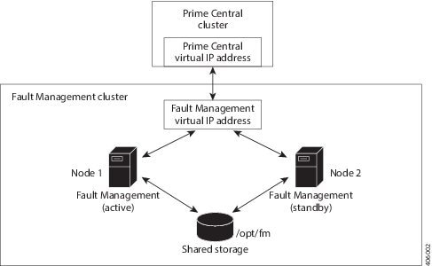
Figure 2-5 shows an example of a Fault Management cluster in an HA configuration.
Figure 2-5 Fault Management Cluster in an HA Configuration
Before You Begin
- Ensure that both PC and FM are installed on different VMs.
- Verify that your system meets all the hardware and software requirements in “Installation Requirements” in the Cisco Prime Central 2.0 Quick Start Guide.
- If you changed the default installation folder (/opt/fm/primeusr/faultmgmt), make the equivalent changes in the following files (look for the section titled “Require manual definition” in each file):
Fault Management HA Setup on RHEL 6.5 or RHEL 6.7 or 6.8
Step 1![]() Create two VMs with the configuration specified in the Cisco Prime Central 2.0 Quick Start Guide.
Create two VMs with the configuration specified in the Cisco Prime Central 2.0 Quick Start Guide.
- Two VMs act as cluster nodes.
- Create two VMs—one with the virtual IP address (virtual hostname) and the other with the node2 IP address (node2 hostname). After the fault management installation is complete, you will then change the virtual IP address to node 1’s IP address (node1 hostname) and then configure the cluster services.
- Shared network storage is required.
Step 2![]() Install RHEL 6.5 or 6.7 or 6.8 on the cluster nodes with the Desktop option selected.
Install RHEL 6.5 or 6.7 or 6.8 on the cluster nodes with the Desktop option selected.
Step 3![]() Disable the firewall on the VMs:
Disable the firewall on the VMs:
Step 4![]() On both cluster nodes, switch the network daemons:
On both cluster nodes, switch the network daemons:
Step 5![]() Disable Security-Enhanced Linux (SELinux) on the VMs:
Disable Security-Enhanced Linux (SELinux) on the VMs:
Adding Clustering to the Installed Red Hat Server (Fault Management)
To install RHEL 6.5, complete the following steps in parallel on both nodes, except where noted:
Note![]() Below steps are specific for RHEL 6.5 and this procedure is also supported for RHEL 6.7 and 6.8. You have to change the folder names and iso file names accordingly for RHEL 6.7 and 6.8.
Below steps are specific for RHEL 6.5 and this procedure is also supported for RHEL 6.7 and 6.8. You have to change the folder names and iso file names accordingly for RHEL 6.7 and 6.8.
Step 1![]() Create local directories named /rhel and /cdrom-6.5.
Create local directories named /rhel and /cdrom-6.5.
Step 2![]() Copy the.iso file that was used for the node installation to the /rhel directory.
Copy the.iso file that was used for the node installation to the /rhel directory.
Step 3![]() Mount the /rhel.iso file to /cdrom-6.5:
Mount the /rhel.iso file to /cdrom-6.5:
Note![]() To permanently mount the drive, update the /etc/fstab file. See http://docs.redhat.com/docs/en-US/Red_Hat_Enterprise_Linux/4/html/Introduction_To_System_Administration/s2-storage-mount-fstab.html.
To permanently mount the drive, update the /etc/fstab file. See http://docs.redhat.com/docs/en-US/Red_Hat_Enterprise_Linux/4/html/Introduction_To_System_Administration/s2-storage-mount-fstab.html.
Step 4![]() Create a file named /etc/yum.repos.d/local.repo. Use UNIX format and be sure there are no spaces before lines.
Create a file named /etc/yum.repos.d/local.repo. Use UNIX format and be sure there are no spaces before lines.
Step 5![]() Save the newly created file in local.repo, as follows:
Save the newly created file in local.repo, as follows:
Step 6![]() Keep the nodes synchronized:
Keep the nodes synchronized:
Step 7![]() Edit the /etc/hosts file to add the node information; for example:
Edit the /etc/hosts file to add the node information; for example:
Step 8![]() Generate an SSH key for the root user:
Generate an SSH key for the root user:
Step 9![]() (On the first node only) Share the node’s public key with the other node so that dynamically creating a secure shell between the nodes does not prompt for a password:
(On the first node only) Share the node’s public key with the other node so that dynamically creating a secure shell between the nodes does not prompt for a password:
Step 10![]() Verify that the.ssh directory has 700 permission and the.ssh/id_rsa file has 600 permission:
Verify that the.ssh directory has 700 permission and the.ssh/id_rsa file has 600 permission:
Step 11![]() Verify that your SSH is working without an authentication or password prompt:
Verify that your SSH is working without an authentication or password prompt:
a.![]() On node fm-ha-node1.cisco.com, enter:
On node fm-ha-node1.cisco.com, enter:
b.![]() On node fm-ha-node2.cisco.com, enter:
On node fm-ha-node2.cisco.com, enter:
c.![]() If you are prompted for a password, check the permissions of all folders and files that you modified in the preceding steps.
If you are prompted for a password, check the permissions of all folders and files that you modified in the preceding steps.
d.![]() If you are prompted to continue connecting, enter yes. (The prompt should appear only the first time you use SSH to connect to the node.)
If you are prompted to continue connecting, enter yes. (The prompt should appear only the first time you use SSH to connect to the node.)
Configuring Multipath
To configure multipath, complete the following steps in parallel on both nodes, except where noted:
Note![]() The examples provided use device mapping names such as mpatha and mpathap1; yours may be different.
The examples provided use device mapping names such as mpatha and mpathap1; yours may be different.
Step 2![]() Set up multipath. Execute the below commands in sequence:
Set up multipath. Execute the below commands in sequence:
Step 3![]() Check for available disks. The names of the multipath disks must be identical on both nodes:
Check for available disks. The names of the multipath disks must be identical on both nodes:
In the output, note mpatha, which is the multipath virtual device or disk that you will use later as shared storage.
Adding Shared Partitions
To add shared partitions, complete the following steps in parallel on both nodes, except where noted:
Note![]() The examples provided use device mapping names such as mpatha and mpathap1; yours may be different.
The examples provided use device mapping names such as mpatha and mpathap1; yours may be different.
Step 1![]() (On the first node only) Create a 100-GB, shared partition:
(On the first node only) Create a 100-GB, shared partition:
Step 3![]() Check for new partitions:
Check for new partitions:
Step 4![]() (On the first node only) Format the new shared partition:
(On the first node only) Format the new shared partition:
Step 5![]() Create target locations on both nodes:
Create target locations on both nodes:
Step 6![]() Verify that both nodes can mount and unmount the shared storage:
Verify that both nodes can mount and unmount the shared storage:
a.![]() On the first node, mount the shared storage and save a file that contains only the value 1 to the shared storage. The test.txt file should exist in the list of contents of /opt/fm:
On the first node, mount the shared storage and save a file that contains only the value 1 to the shared storage. The test.txt file should exist in the list of contents of /opt/fm:
b.![]() On the second node, mount the shared storage and verify that the test.txt file exists and contains the value 1 :
On the second node, mount the shared storage and verify that the test.txt file exists and contains the value 1 :
If you cannot mount or unmount the shared storage, or if the test.txt file does not exist when you mount it to the second node, your multipath is not set up correctly.
Installing Prime Central Fault Management
Step 1![]() Verify that both fault management VMs can ping each other via the hostname and IP address. Also verify that the both VMs can ping the PC cluster nodes and luci node via the hostname and IP address.
Verify that both fault management VMs can ping each other via the hostname and IP address. Also verify that the both VMs can ping the PC cluster nodes and luci node via the hostname and IP address.
Step 2![]() Verify that both VMs can ssh to each other without using the configured password.
Verify that both VMs can ssh to each other without using the configured password.
Step 3![]() Insert the Cisco Prime Central 2.0.0 USB, navigate to the High Availability/RHCS VMWare ESXi Local HA/Fault Management folder, and locate the primefm_v2.0.0_ha_node.tar.gz file.
Insert the Cisco Prime Central 2.0.0 USB, navigate to the High Availability/RHCS VMWare ESXi Local HA/Fault Management folder, and locate the primefm_v2.0.0_ha_node.tar.gz file.
Step 4![]() Use SSH to connect to the virtual IP node.
Use SSH to connect to the virtual IP node.
Step 5![]() Copy the primefm_v2.0.0_ha_node.tar.gz file to the virtual IP node.
Copy the primefm_v2.0.0_ha_node.tar.gz file to the virtual IP node.
Step 6![]() Back up the /root/ha-stuff/fm and /usr/local/bin directories.
Back up the /root/ha-stuff/fm and /usr/local/bin directories.
Step 7![]() Mount the partition to the /opt/fm directory on the virtual IP node:
Mount the partition to the /opt/fm directory on the virtual IP node:
Step 8![]() Distribute the file on both nodes:
Distribute the file on both nodes:
Step 9![]() Navigate to the top-level Fault Management folder and copy the FM2.0.0Build.tar.gz file to the /root/ha-stuff/fm directory:
Navigate to the top-level Fault Management folder and copy the FM2.0.0Build.tar.gz file to the /root/ha-stuff/fm directory:
Step 10![]() Specify all necessary properties in the fm_install.properties file.
Specify all necessary properties in the fm_install.properties file.
Step 11![]() Change HOSTNAME in /etc/sysconfig/network to match the value of PRIMEFM_SERVER_HOSTNAME in fm_install.properties file.
Change HOSTNAME in /etc/sysconfig/network to match the value of PRIMEFM_SERVER_HOSTNAME in fm_install.properties file.
Note![]() The hostname must be a Fully Qualified Distinguished Name (FQDN).
The hostname must be a Fully Qualified Distinguished Name (FQDN).
For example: prime-fm-service.cisco.com
Step 12![]() Change active hostname to the host name used in step 11 (the virtual FQDN hostname) using the command:
Change active hostname to the host name used in step 11 (the virtual FQDN hostname) using the command:
Step 13![]() Install Fault Management:
Install Fault Management:
Step 14![]() After the installation is complete, make sure that FM can be started properly.
After the installation is complete, make sure that FM can be started properly.
Step 15![]() Freeze the Prime Central cluster and then restart the integration layer so that Prime Central displays Fault Management’s status as UP.
Freeze the Prime Central cluster and then restart the integration layer so that Prime Central displays Fault Management’s status as UP.
Step 16![]() Stop Fault Management:
Stop Fault Management:
Step 17![]() Change the IP address from virtual IP (hostname) to node 1’s IP address (hostname).
Change the IP address from virtual IP (hostname) to node 1’s IP address (hostname).
Revert to use the original hostname, if there are any changes in /etc/sysconfig/network file (in Step 11![]() ).
).
Setting Up the Fault Management Cluster Service
Step 1![]() Install the ricci RPMs:
Install the ricci RPMs:
Step 2![]() Start the ricci daemon and configure it to start on boot:
Start the ricci daemon and configure it to start on boot:
Step 3![]() Set the ricci user password:
Set the ricci user password:
You will need to enter this password later.
At this point, both cluster nodes should be running the ricci servers and be ready to be managed by the cluster web user interface (luci).
Configuring the Cluster Web User Interface (luci)
Complete the following procedure to configure luci on the third VM for use with Prime Central Fault Management.
Step 1![]() Launch the URL listed in the last line of the system output (https://prime-ha-luci.cisco.com:8084, in this example) and log in as the root user when prompted.
Launch the URL listed in the last line of the system output (https://prime-ha-luci.cisco.com:8084, in this example) and log in as the root user when prompted.
Step 2![]() Verify that the RHEL DVD is mounted on both cluster nodes.
Verify that the RHEL DVD is mounted on both cluster nodes.
Step 3![]() Select Manage Clusters > Create and then specify a name for the cluster (for example, PrimeFMCluster).
Select Manage Clusters > Create and then specify a name for the cluster (for example, PrimeFMCluster).
Step 4![]() Enter the name (fully-qualified domain name or name specified in the /etc/hosts directory) and password (the password for the user ricci) for the first cluster node.
Enter the name (fully-qualified domain name or name specified in the /etc/hosts directory) and password (the password for the user ricci) for the first cluster node.
Step 5![]() Click Add Another Node and enter the same information described in Step 4 for the second cluster node.
Click Add Another Node and enter the same information described in Step 4 for the second cluster node.
Step 6![]() Do the following, and then click Create Cluster:
Do the following, and then click Create Cluster:
Assuming that the nodes can be contacted, luci will set up each cluster node and add each node to the cluster.
After each node has been set up, the High Availability Management screen opens.
Step 7![]() Create a failover domain:
Create a failover domain:
a.![]() Select the Failover Domains tab and then click Add.
Select the Failover Domains tab and then click Add.
–![]() Name: Enter a name for the failover domain.
Name: Enter a name for the failover domain.
–![]() Prioritized: Select this check box.
Prioritized: Select this check box.
–![]() Restricted: Select this check box.
Restricted: Select this check box.
–![]() No Failback: Select this check box.
No Failback: Select this check box.
–![]() Member: Select the check box for each node.
Member: Select the check box for each node.
–![]() Priority. In the Priority column, enter 1 for node1 and 2 for node2.
Priority. In the Priority column, enter 1 for node1 and 2 for node2.
Step 8![]() Configure fence devices appropriate for the hardware you have, adding a fence device and instance for each node.
Configure fence devices appropriate for the hardware you have, adding a fence device and instance for each node.
The settings you need to configure depend on your particular hardware and software configuration. Refer to the Cluster Administration Guide for help with configuring fence devices.
Complete the following steps to configure VMware fencing:
a.![]() Retrieve the UUID for prime-ha-node1.cisco.com:
Retrieve the UUID for prime-ha-node1.cisco.com:
Keep in mind that VM-Name is the name given to the VM during VM creation, not its hostname.
b.![]() Repeat the previous step for prime-ha-node2.cisco.com.
Repeat the previous step for prime-ha-node2.cisco.com.
c.![]() In luci, select the Fence Devices tab and then click Add.
In luci, select the Fence Devices tab and then click Add.
–![]() Fence type: Select VMWare Fencing (SOAP Interface).
Fence type: Select VMWare Fencing (SOAP Interface).
–![]() Name: Enter a descriptive name for the fence device.
Name: Enter a descriptive name for the fence device.
–![]() IP Address or Hostname: Enter the appropriate VCenter IP address or hostname.
IP Address or Hostname: Enter the appropriate VCenter IP address or hostname.
–![]() IP Port (optional): Leave blank.
IP Port (optional): Leave blank.
–![]() Login: Enter the VCenter username.
Login: Enter the VCenter username.
–![]() Password: Enter the VCenter password.
Password: Enter the VCenter password.
Leave the rest of the fields as is or blank.
f.![]() Select the Nodes tab and then select your first node by clicking its name.
Select the Nodes tab and then select your first node by clicking its name.
g.![]() At the bottom of the node’s window, click Add Fence Method.
At the bottom of the node’s window, click Add Fence Method.
h.![]() Enter a name and then click Submit. Now select Add Fence Instance that appears inside the method box and fill it out as described below:
Enter a name and then click Submit. Now select Add Fence Instance that appears inside the method box and fill it out as described below:
i.![]() Select the fencing device you configured in Step 8d and do the following:
Select the fencing device you configured in Step 8d and do the following:
–![]() VM UUID: Enter the UUID you retrieved in Step 8a (for example, 4209838d-1e91-104c-9f5c-1181ad87ddd8).
VM UUID: Enter the UUID you retrieved in Step 8a (for example, 4209838d-1e91-104c-9f5c-1181ad87ddd8).
–![]() Use SSL: Select this check box. Fencing will not work unless you do so.
Use SSL: Select this check box. Fencing will not work unless you do so.
j.![]() Repeat Steps 8f through 8i for your second node.
Repeat Steps 8f through 8i for your second node.
Note![]() We recommend that you check the bottom of this window for each node and verify that all of the required daemons are running before you test fencing.
We recommend that you check the bottom of this window for each node and verify that all of the required daemons are running before you test fencing.
Step 9![]() To configure KVM fencing, complete the following steps:
To configure KVM fencing, complete the following steps:
a.![]() Retrieve the UUID for prime-pc-node1.cisco.com by executing the below command on the KVM host:
Retrieve the UUID for prime-pc-node1.cisco.com by executing the below command on the KVM host:
b.![]() Repeat the previous step for prime-pc-node2.cisco.com.
Repeat the previous step for prime-pc-node2.cisco.com.
c.![]() In luci, select the Fence Devices tab, and then click Add.
In luci, select the Fence Devices tab, and then click Add.
d.![]() From the Fence Type drop-down list, choose fence_virt(Multicast Mode).
From the Fence Type drop-down list, choose fence_virt(Multicast Mode).
e.![]() In the Name field, enter a descriptive name.
In the Name field, enter a descriptive name.
Note![]() Leave the other fields as is or blank.
Leave the other fields as is or blank.
g.![]() Select the Nodes tab, and then select your primary node by clicking its name.
Select the Nodes tab, and then select your primary node by clicking its name.
h.![]() Click Add Fence method that is available at the bottom of the node window.
Click Add Fence method that is available at the bottom of the node window.
i.![]() Enter a name, and then click Submit. Select the Add Fence Instance that appears inside the method box, and then enter the details as specified below:
Enter a name, and then click Submit. Select the Add Fence Instance that appears inside the method box, and then enter the details as specified below:
–![]() Select the fencing device that you configured in step 9d, and then in the Domain name field, enter the domain name. For example, you can enter 4209838d-1e91-104c-9f5c-1181ad87ddd8.
Select the fencing device that you configured in step 9d, and then in the Domain name field, enter the domain name. For example, you can enter 4209838d-1e91-104c-9f5c-1181ad87ddd8.
Note![]() Leave the Delay field as blank.
Leave the Delay field as blank.
Step 10![]() Set up the network configuration:
Set up the network configuration:
c.![]() Select the UDP Unicast (UDPU) radio button and then click Apply.
Select the UDP Unicast (UDPU) radio button and then click Apply.
Setting Up Shared Resources
You will next create the cluster service (named PrimeService in this example). To begin, open the High Availability Management page (luci) in a browser. From there, you will:
- Identify the virtual IP address for this cluster
- Identify the PrimeService service and add the virtual IP address to this service
At several points, you will run commands from the cluster nodes (ricci) to verify that the configuration you set in luci is working.
Identifying the Cluster Service's Virtual IP Address
From luci, do the following to identify the cluster service's virtual IP address:
Step 1![]() Select the cluster name (for example, PrimeCluster).
Select the cluster name (for example, PrimeCluster).
Step 2![]() Select the Resources tab and then click Add.
Select the Resources tab and then click Add.
Step 4![]() Enter the following information:
Enter the following information:
Creating the Prime Fault Management Service
From luci, with the cluster still selected, add a new service and associate it with the IP address.
Step 1![]() Select the Service Groups tab and then click Add.
Select the Service Groups tab and then click Add.
Step 2![]() Enter the following information for the new service group:
Enter the following information for the new service group:
Step 4![]() Select the IP address you added earlier and then click Submit.
Select the IP address you added earlier and then click Submit.
Step 5![]() Wait 5 minutes and then reboot both cluster nodes.
Wait 5 minutes and then reboot both cluster nodes.
After the VMs come back online, the PrimeFMService service should up and running.
Adding Mount Points and Setting Up File Systems
In the following procedure, you will create mount points on the two nodes. After the mount points have been set up, you can then configure the resources necessary to mount file systems to the proper locations.
Step 1![]() Create a file system resource:
Create a file system resource:
a.![]() From luci, select the Resources tab and then click Add.
From luci, select the Resources tab and then click Add.
b.![]() From the Add Resource to Cluster window, select Filesystem from the dropdown list and then do the following:
From the Add Resource to Cluster window, select Filesystem from the dropdown list and then do the following:
–![]() Name: Enter the name of the file system resource.
Name: Enter the name of the file system resource.
–![]() Filesystem type: Select the ext4 option.
Filesystem type: Select the ext4 option.
–![]() Mount point: Enter the mount point path—/opt/fm
Mount point: Enter the mount point path—/opt/fm
–![]() Device, FS label, or UUID: Enter the appropriate path—in this example, /dev/mapper/mpath2p1
Device, FS label, or UUID: Enter the appropriate path—in this example, /dev/mapper/mpath2p1
–![]() Leave the Mount options and Filesystem ID (optional) field blank.
Leave the Mount options and Filesystem ID (optional) field blank.
–![]() Select the Force Unmount check box.
Select the Force Unmount check box.
–![]() Select the Reboot host node if unmount fails check box.
Select the Reboot host node if unmount fails check box.
Step 2![]() Add the file system resource to the PrimeService service group:
Add the file system resource to the PrimeService service group:
a.![]() From luci, select the Service Groups tab.
From luci, select the Service Groups tab.
b.![]() In the Name column, select the PrimeFMService service group name.
In the Name column, select the PrimeFMService service group name.
c.![]() At the bottom of the page, click Add Resource.
At the bottom of the page, click Add Resource.
d.![]() Click Select a Resource Type.
Click Select a Resource Type.
The filesystem resources you added should appear in the list.
e.![]() From the list, click the filesystem entries you added in the previous step.
From the list, click the filesystem entries you added in the previous step.
Step 3![]() Log in to the node currently running the PrimeFMService service.
Log in to the node currently running the PrimeFMService service.
Step 4![]() Verify that the logical volume ext4 filesystems are mounted with read/write privileges on the node running the PCService service:
Verify that the logical volume ext4 filesystems are mounted with read/write privileges on the node running the PCService service:
Step 5![]() Verify that the logical volume ext4 filesystems are not mounted on the node which is not running the PCService service:
Verify that the logical volume ext4 filesystems are not mounted on the node which is not running the PCService service:
Adding Scripts to the Prime Central Cluster Service
Step 1![]() Add the fm.sh script resource:
Add the fm.sh script resource:
a.![]() From luci, select the Resources tab and then click Add.
From luci, select the Resources tab and then click Add.
b.![]() From the Add Resource to Cluster window, select Script from the dropdown list and then enter the following information:
From the Add Resource to Cluster window, select Script from the dropdown list and then enter the following information:
–![]() Full Path to Script File: Directory in which the script will reside—/usr/local/bin/fm.sh
Full Path to Script File: Directory in which the script will reside—/usr/local/bin/fm.sh
Step 2![]() Add script resources to the PrimeService service group:
Add script resources to the PrimeService service group:
a.![]() From luci, select the Service Groups tab.
From luci, select the Service Groups tab.
b.![]() In the Name column, select the PrimeFMService service group name.
In the Name column, select the PrimeFMService service group name.
c.![]() At the bottom of the page, click Add Resource.
At the bottom of the page, click Add Resource.
d.![]() Click Select a Resource Type.
Click Select a Resource Type.
The script resource you added should appear in the list.
e.![]() Click the script entries from the list you added in the previous step.
Click the script entries from the list you added in the previous step.
Verifying the PrimeService Service Can Be Reached
From each of the cluster nodes, check the status of the PrimeService services you created. Then, from any machine on the network, verify that you can reach the cluster from the IP address you assigned.
Step 1![]() From a shell on each of the cluster nodes, verify that the service group is running by entering the following commands (in bold):
From a shell on each of the cluster nodes, verify that the service group is running by entering the following commands (in bold):
Step 2![]() From a shell anywhere that can reach the cluster over the network, verify that you can ping the IP address associated with the IP address resource you created previously (see Creating the Prime Service):
From a shell anywhere that can reach the cluster over the network, verify that you can ping the IP address associated with the IP address resource you created previously (see Creating the Prime Service):
Note![]() To end the ping, enter Ctrl + C.
To end the ping, enter Ctrl + C.
Step 4![]() Verify that the service has been relocated successfully to the other node.
Verify that the service has been relocated successfully to the other node.
Checking the Cluster Services
Step 1![]() Review the cluster log file in /var/log/messages.
Review the cluster log file in /var/log/messages.
Step 2![]() After the Fault Management service is running in an HA cluster, you cannot restart its components (such as Netcool/Impact, OMNIbus, and Tivoli Common Reporting [TCR]) without first freezing the cluster. After you restart the component, you can unfreeze the cluster.
After the Fault Management service is running in an HA cluster, you cannot restart its components (such as Netcool/Impact, OMNIbus, and Tivoli Common Reporting [TCR]) without first freezing the cluster. After you restart the component, you can unfreeze the cluster.
To restart a Fault Management component:
a.![]() On the active Fault Management node, enter:
On the active Fault Management node, enter:
b.![]() Use SSH to connect to the Fault Management virtual machine and enter:
Use SSH to connect to the Fault Management virtual machine and enter:
c.![]() Use SSH to connect to the active Fault Management node and enter:
Use SSH to connect to the active Fault Management node and enter:
Troubleshooting
The following troubleshooting steps help to solve common problems in HA configuration.
Problem The HA installation fails.
Solution Check the log files to locate the problem and take the appropriate action. Log files contain detailed information about request processing and exceptions and are your best diagnostic tool for troubleshooting. See “Troubleshooting the Installation” in the Cisco Prime Central 2.0 Quick Start Guide.
Problem Prime Central does not start in a clustered setup.
Solution Check the /var/log/messages files for failure to either mount the shared storage or add the virtual IP address. If the shared storage failed to mount, shut down the cluster and verify that you can manually add the shared storage to a node. (Be sure to unmount it after your test.)
If the virtual IP address was not added, verify that it is in the same subnet as the nodes and is not in use by any other computer in the network.
If you find that /usr/local/bin/pc.sh start failed, check /var/halogs/pc.log, which will tell you if the database or other Prime Central components failed to start.Then, to determine which component failed to start:
1.![]() Stop the luci, ricci, rgmanager, and cman services on both nodes to shut down the cluster.
Stop the luci, ricci, rgmanager, and cman services on both nodes to shut down the cluster.
2.![]() On the node where you originally installed Prime Central:
On the node where you originally installed Prime Central:
b.![]() Add the virtual IP address.
Add the virtual IP address.
c.![]() Verify that all services have stopped:
Verify that all services have stopped:
e.![]() Check the output from each of the preceding commands to locate the problem.
Check the output from each of the preceding commands to locate the problem.
Problem You receive the error “<err> 'fsck -p /dev/mapper/mpath2p1' failed, error=4; check /tmp/fs-vmpcfs.fsck.log.mq4986 for errors.”
Solution Enter the following command and reboot when it is finished running:
Problem You receive the error “Timeout exceeded while waiting for ‘/images/fm_status.sh’” in /var/log/messages.
Solution Verify that you can use SSH to connect to each node and virtual machine without an authentication or password prompt. If SSH prompts for authentication or a password, the Prime Central and Fault Management services cannot start.
Problem Your environment uses the wrong fencing device.
Solution The examples in this guide use fence_vmware for VMware Hypervisor and fence_virt for KVM Hypervisor. For information about which fencing device to use in your environment, see the Red Hat Enterprise Linux 6 Cluster Administration: Configuring and Managing the High Availability Add-On.
Problem The cman and rgmanager services do not start.
Solution Check the log files in /var/log/messages and /var/log/cluster. Use the following tool to verify that your multicast address is correct: http://juliandyke.wordpress.com/2010/12/03/testing-multicasting-for-oracle-11-2-0-2-grid-infrastructure/.
Problem Cannot stop the cluster.
Solution Use luci or the command line to shut down your cluster:
- luci—Select the cluster; then, from the drop-down list, choose Stop this cluster.
- Command line—Alternating between the two nodes, shut down the services in the reverse order in which you started them. For example, enter the stop command for rgmanager on node1; then, enter it on node2. Enter the stop command for cman on node1; then, enter it on node2.
Problem When trying to unmount the shared storage, a “device is busy” message is returned.
Solution Verify that all cluster services have stopped and that you have closed all terminal sessions that are accessing the shared storage location. To determine which user is accessing the shared storage, enter:
Problem You do not know if the node can support virtualization.
If the command returns no output, the node does not support virtualization.
If the command output contains vmx or svm flags, the node supports virtualization. For example:
Problem Cannot test the cluster.conf file.
Solution Use rg_test commands. For example:
Problem When you reboot one or both nodes, the node is fenced before it can join the cluster.
Solution To start up, the node might require an additional fencing delay. Edit your cluster.conf file by increasing the value of the post_join_delay attribute:
Problem After you relocate the Prime Central service, the integration layer is shown in the Prime Central Suite Monitoring portlet > Applications tab, but its state is Down.
Solution On servers where the hardware requirements are at or below the minimum for Prime Central high availability, the integration layer requires more time to start up. Do the following:
1.![]() On the active node where Prime Central is running, locate the /opt/pc/primecentral/esb/etc/com.cisco.prime.esb.jms.cfg file.
On the active node where Prime Central is running, locate the /opt/pc/primecentral/esb/etc/com.cisco.prime.esb.jms.cfg file.
2.![]() Edit the file by increasing the waitForStart attribute for the jmsvm.internalBrokerURL property. (If the line is commented, uncomment it.)
Edit the file by increasing the waitForStart attribute for the jmsvm.internalBrokerURL property. (If the line is commented, uncomment it.)
The default waitForStart value is 10,000 milliseconds; increase it depending on the slowness of your server. For example, to increase the waitForStart value to 30 seconds, enter:
Problem The Prime Central portal does not look correct.
Solution The cluster manager might have relocated the server. Clear your browser cache and refresh your screen; then, log back in to the Prime Central portal.
Problem You need to restart a Prime Central or Fault Management component in an HA environment.
Solution Prime Central contains components such as the portal, integration layer, and database. Fault Management contains components such as Netcool/Impact, OMNIbus, and TCR. If you need to perform maintenance on a specific component, you must freeze the HA cluster before you can stop the component. After you restart the component, you can unfreeze the cluster.
Problem After adding multipath, you cannot see the multipath names when listing the /dev/mapper directory.
2.![]() Change the find_multipaths value to no.
Change the find_multipaths value to no.
You should now see the multipath names.
Problem You receive the following error while mounting the storage:
Problem The fmctl status command shows that Fault Management started in KVM, but hangs in “starting” status in the cluster.
Solution Check the SSH password-less connection between the two nodes and KVM.
Problem During HA installation in a VMware and KVM environment, you may see the following warning about the 32-bit gtk2 RPM package on the console:
Solution This warning is harmless and does not indicate a problem which will affect either the installation or operation of Fault Management.
Problem -import: unknown option is displayed during installation.
Solution This error message does not indicate an actual problem and can be ignored.
Problem Error messages are displayed during the installation of the Fault Management component.
Solution The error messages do not indicate actual problems and can be ignored.
Problem Unsuccessful installation.
Solution When an installation fails, perform the below Cleanup procedure, along with the uninstall script:
1.![]() Run uninstall script and remove directories manually.
Run uninstall script and remove directories manually.
Upgrading to Prime Central 2.0.0 in a Local Redundancy HA Configuration
Note![]() As part of Prime Central 2.0.0 release, Direct upgrade from 1.4.1 to 2.0.0, 1.5 to 2.0.0 and 1.5.3 to 2.0.0 are supported. For every upgrade follow the same steps mentioned below.
As part of Prime Central 2.0.0 release, Direct upgrade from 1.4.1 to 2.0.0, 1.5 to 2.0.0 and 1.5.3 to 2.0.0 are supported. For every upgrade follow the same steps mentioned below.
If you are upgrading directly from 1.4.1 to 2.0.0, as part of Prime Central 2.0.0 release, data models have been changed from PSI (Prime Service Inventory) to SSI (Sub System Inventory) internally. Before performing the upgrade of Prime Central application from Release 1.4.1 to Release 2.0.0, it is therefore recommended to check whether there is any inconsistent PSI data. To detect any potential inconsistencies with PSI, contact the Cisco support.
Step 2![]() Insert the Cisco Prime Central 2.0.0 USB, navigate to the High Availability/RHCS Bare Metal Local HA/Prime Central folder, and locate the primecentral_v2.0.0_ha_vm.tar.gz file.
Insert the Cisco Prime Central 2.0.0 USB, navigate to the High Availability/RHCS Bare Metal Local HA/Prime Central folder, and locate the primecentral_v2.0.0_ha_vm.tar.gz file.
Step 3![]() Use SSH to connect to the first node.
Use SSH to connect to the first node.
Step 4![]() Copy the primecentral_v2.0.0_ha_vm.tar.gz file to the first node.
Copy the primecentral_v2.0.0_ha_vm.tar.gz file to the first node.
Step 5![]() Back up the following directories on both nodes:
Back up the following directories on both nodes:
Step 7![]() Navigate to the Base Application folder and copy primecentral_v2.0.0.bin and all available.zip files to the /root/ha-stuff/pc directory:
Navigate to the Base Application folder and copy primecentral_v2.0.0.bin and all available.zip files to the /root/ha-stuff/pc directory:
Step 8![]() Perform the following on the first node:
Perform the following on the first node:
a.![]() Mount the shared partitions:
Mount the shared partitions:
b.![]() Add a virtual IP cluster service address for the Prime Central service:
Add a virtual IP cluster service address for the Prime Central service:
c.![]() Update the install.properties file and verify if all required properties have values. Review the comments at the top of the install.properties file for details.
Update the install.properties file and verify if all required properties have values. Review the comments at the top of the install.properties file for details.
Note![]() To install Prime Central silently, you must edit the /root/ha-stuff/pc/install.properties file. See ‘Sample install.properties Files’ in the Cisco Prime Central 2.0.0 Quick Start Guide.
To install Prime Central silently, you must edit the /root/ha-stuff/pc/install.properties file. See ‘Sample install.properties Files’ in the Cisco Prime Central 2.0.0 Quick Start Guide.
Note![]() Run the PrimeCentral.sh script by adding the preceding command-line parameters. If you do not add the command-line parameters, you are prompted for the required data.
Run the PrimeCentral.sh script by adding the preceding command-line parameters. If you do not add the command-line parameters, you are prompted for the required data.
e.![]() In another terminal window, check the upgrade process:
In another terminal window, check the upgrade process:
f.![]() After the upgrade succeeds, start Prime Central:
After the upgrade succeeds, start Prime Central:
g.![]() Verify if Prime Central is running correctly. If so, stop it:
Verify if Prime Central is running correctly. If so, stop it:
h.![]() Remove virtual IP addresses:
Remove virtual IP addresses:
When upgrade completes, log files will be available in ~/upgrade/1.5.3.0-2.0.0.0/upgrade.log.
Upgrading to Prime Central Fault Management 2.0 in a Local Redundancy HA Configuration
Note![]() As part of Prime Central Fault Management 2.0.0 release, Direct upgrade from 1.4.1 to 2.0.0, 1.5 to 2.0.0 and 1.5.3 to 2.0.0 are supported. For every upgrade follow the same steps mentioned below.
As part of Prime Central Fault Management 2.0.0 release, Direct upgrade from 1.4.1 to 2.0.0, 1.5 to 2.0.0 and 1.5.3 to 2.0.0 are supported. For every upgrade follow the same steps mentioned below.
Step 2![]() Insert the Cisco Prime Central 2.0 USB.
Insert the Cisco Prime Central 2.0 USB.
Step 3![]() Navigate to the High Availability/RHCS VMWare ESXi Local HA/Fault Management folder, and locate the primefm_v2.0_ha_node.tar.gz file.
Navigate to the High Availability/RHCS VMWare ESXi Local HA/Fault Management folder, and locate the primefm_v2.0_ha_node.tar.gz file.
Step 4![]() Use SSH to connect to the virtual IP node.
Use SSH to connect to the virtual IP node.
Step 5![]() Copy the primefm_v2.0_ha_node.tar.gz file to the virtual IP node.
Copy the primefm_v2.0_ha_node.tar.gz file to the virtual IP node.
Step 6![]() Back up the /root/ha-stuff/fm and /usr/local/bin directories.
Back up the /root/ha-stuff/fm and /usr/local/bin directories.
Step 7![]() Mount the partition to the /opt/fm directory on the virtual IP node:
Mount the partition to the /opt/fm directory on the virtual IP node:
Step 9![]() Navigate to the top-level Fault Management folder and copy the FM2.0Build.tar.gz file to the /root/ha-stuff/fm directory:
Navigate to the top-level Fault Management folder and copy the FM2.0Build.tar.gz file to the /root/ha-stuff/fm directory:
Step 10![]() Specify all of the necessary properties in the fm_install.properties file.
Specify all of the necessary properties in the fm_install.properties file.
Change HOSTNAME in /etc/sysconfig/network to match PRIMEFM_SERVER_HOSTNAME. For example:
Step 12![]() Mount the shared partitions:
Mount the shared partitions:
Step 13![]() Start Fault Management:
Start Fault Management:
Step 14![]() Upgrade Fault Management:
Upgrade Fault Management:
Step 15![]() After the upgrade is complete, make sure that FM can be started properly.
After the upgrade is complete, make sure that FM can be started properly.
Step 16![]() Freeze the Prime Central cluster and then restart the integration layer so that Prime Central displays Fault Management’s status as UP.
Freeze the Prime Central cluster and then restart the integration layer so that Prime Central displays Fault Management’s status as UP.
Step 17![]() Stop and start Fault Management:
Stop and start Fault Management:
Step 18![]() Change the IP address from virtual IP (hostname) to node 1’s IP address (hostname). Reverse the hostname, if there are any changes in /etc/sysconfig/network file (in Step 10).
Change the IP address from virtual IP (hostname) to node 1’s IP address (hostname). Reverse the hostname, if there are any changes in /etc/sysconfig/network file (in Step 10).
Upgrading RHEL Operating System
The Operating System (OS) upgrade procedure supports Prime Central 1.5.1 customers to perform upgrade of Operating System from RHEL 5.8 to 6.5 and inline upgrade from RHEL 6.5 to 6.7. For more information, refer the Cisco Prime Central RHEL Operating System Upgrade guide.
Rollback Procedure for Prime Central
After upgrading to Prime Central 2.0.0, you may find the need to revert to the previous version. To do so, complete the following procedure.
Note![]() By default the primeusr home folder is /opt/pc/primecentral. If your primeusr home folder is different, specify that folder instead.
By default the primeusr home folder is /opt/pc/primecentral. If your primeusr home folder is different, specify that folder instead.
Step 1![]() Login as the root user and make sure Cluster is frozen:
Login as the root user and make sure Cluster is frozen:
Step 2![]() Confirm that the /opt/pc/primecentral_2.0.0_backup folder was created during upgrade from Prime Central 1.5.3 to Prime Central 2.0.0.
Confirm that the /opt/pc/primecentral_2.0.0_backup folder was created during upgrade from Prime Central 1.5.3 to Prime Central 2.0.0.
a.![]() If the folder was created, proceed to Step 2.
If the folder was created, proceed to Step 2.
b.![]() If the folder was not created, this indicates that there was a disk space issue and the upgrade was not started. You can stop here.
If the folder was not created, this indicates that there was a disk space issue and the upgrade was not started. You can stop here.
Step 3![]() Change ownership of the /opt/primecentral_1.5.3.0_backup folder:
Change ownership of the /opt/primecentral_1.5.3.0_backup folder:
Step 4![]() Stop all Prime Central processes:
Stop all Prime Central processes:
For distributed server environment (portal and IL are in different servers):
- Execute above portalctl stop command on Portal server as primeusr.
- Execute above itgctl stop command on IL server as primeusr.
Step 5![]() Move the primecentral folder to the tmp folder:
Move the primecentral folder to the tmp folder:
Step 6![]() Rename the /opt/primecentral_1.5.3.0_backup folder:
Rename the /opt/primecentral_1.5.3.0_backup folder:
Step 7![]() Restore the /var/.com.zerog.registry.xml file with the backup file: /var/.com.zerog.registry.xml_backup_for_2.0.0 that was created during Prime Central upgrade process. Execute the below commands:
Restore the /var/.com.zerog.registry.xml file with the backup file: /var/.com.zerog.registry.xml_backup_for_2.0.0 that was created during Prime Central upgrade process. Execute the below commands:
Step 8![]() To find the exact time to restore database, back to the timestamp before upgrade.
To find the exact time to restore database, back to the timestamp before upgrade.
Login to the database as sysdba and execute the below query to get the RMAN backup history:
Step 9![]() Change the permissions of ssh key files as below:
Change the permissions of ssh key files as below:
Step 10![]() Restore database (from the backup taken before upgrading to Prime Central 2.0.0)
Restore database (from the backup taken before upgrading to Prime Central 2.0.0)
Note![]() Restore time should be the time of the full backup taken just before the start of upgrade and should be taken from the result of the query executed in Step 7.
Restore time should be the time of the full backup taken just before the start of upgrade and should be taken from the result of the query executed in Step 7.
Database restore log location: /opt/pc/oracle/prime_logs/restore***_***.log
–![]() Login/ssh to external database as root
Login/ssh to external database as root
–![]() Restore full database to the time of backup taken (manually) just before the start of PC upgrade. Use oracle commands:
Restore full database to the time of backup taken (manually) just before the start of PC upgrade. Use oracle commands:
Step 11![]() Start all Prime Central processes:
Start all Prime Central processes:
For distributed server environment (portal and IL are in different servers):
- Execute above portalctl start command on Portal server as primeusr.
- Execute above itgctl start command on IL server as primeusr.
Step 12![]() Execute this step only if it is distributed server environment (portal and IL are in different servers):
Execute this step only if it is distributed server environment (portal and IL are in different servers):
Repeat the above steps 1 to 6 in IL server.
Rollback Procedure for Fault Management
After upgrading to Prime Central Fault Management 2.0.0, you may find the need to revert to the previous version. To do so, complete the following procedure.
Note![]() By default the primeusr home folder is /opt/fm/primeusr. If your primeusr home folder is different, specify that folder
By default the primeusr home folder is /opt/fm/primeusr. If your primeusr home folder is different, specify that folder
Step 1![]() Login as the root user and make sure Cluster is frozen:
Login as the root user and make sure Cluster is frozen:
Step 2![]() Confirm that the faultmgmt_ 1.5.3.0_backup folder was created.
Confirm that the faultmgmt_ 1.5.3.0_backup folder was created.
- If the folder was created, proceed to Step 2.
- If the folder was not created, this indicates that there was a disk space issue and the upgrade was not started. You can stop here.
Step 3![]() Stop all Fault Management processes:
Stop all Fault Management processes:
(As the root user) pkill nco_pad
Step 4![]() Move the faultmgmt folder to the tmp folder:
Move the faultmgmt folder to the tmp folder:
Step 5![]() Move the faultmgmt_ 1.5.3.0_backup folder to the faultmgmt folder:
Move the faultmgmt_ 1.5.3.0_backup folder to the faultmgmt folder:
Step 6![]() Change ownership of the faultmgmt folder. For example:
Change ownership of the faultmgmt folder. For example:
Step 7![]() Restore debackup obtained before the upgrade:
Restore debackup obtained before the upgrade:
Find the following line and change jre 1.8 to jre 1.7:
Step 9![]() As the root user, start the nco_pad process. For example:
As the root user, start the nco_pad process. For example:
Step 10![]() Perform the below mentioned steps:
Perform the below mentioned steps:
1.![]() Login to the Prime Central portlet.
Login to the Prime Central portlet.
2.![]() Remove Fault Management from the Suite Monitoring portlet.
Remove Fault Management from the Suite Monitoring portlet.
3.![]() Logout from the Prime Central portlet.
Logout from the Prime Central portlet.
As a root user, execute the below commands:
Step 11![]() Reintegrate Fault Management with Prime Central:
Reintegrate Fault Management with Prime Central:
Step 12![]() Restore the /var/.com.zerog.registry.xml file with the backup file: /var/.com.zerog.registry.xml_backup_for_1.5.3 that was created during Prime Central Fault Management upgrade process. Execute below commands:
Restore the /var/.com.zerog.registry.xml file with the backup file: /var/.com.zerog.registry.xml_backup_for_1.5.3 that was created during Prime Central Fault Management upgrade process. Execute below commands:
Uninstalling Prime Central Fault Management
Note![]() If you are also uninstalling Prime Central, you must uninstall the Fault Management component first.
If you are also uninstalling Prime Central, you must uninstall the Fault Management component first.
Step 1![]() From the Prime Central portal, choose Administration > System > Suite Monitoring > Applications tab, and remove Fault Management.
From the Prime Central portal, choose Administration > System > Suite Monitoring > Applications tab, and remove Fault Management.
Step 2![]() Use SSH to connect to the Prime Central active node and do the following:
Use SSH to connect to the Prime Central active node and do the following:
a.![]() Freeze the Prime Central cluster:
Freeze the Prime Central cluster:
b.![]() Restart the integration layer:
Restart the integration layer:
c.![]() Unfreeze the Prime Central cluster:
Unfreeze the Prime Central cluster:
Step 3![]() From the luci web interface, stop the Fault Management Service.
From the luci web interface, stop the Fault Management Service.
Step 4![]() Mount and add the virtual IP address to the node that was used for the Prime Central installation:
Mount and add the virtual IP address to the node that was used for the Prime Central installation:
Step 5![]() Use SSH to connect to the Prime Central Fault Management virtual machine and do the following:
Use SSH to connect to the Prime Central Fault Management virtual machine and do the following:
a.![]() Navigate to the /var/adm/cisco/uninstall/Uninstall_Prime_Central_Fault_Management folder.
Navigate to the /var/adm/cisco/uninstall/Uninstall_Prime_Central_Fault_Management folder.
The uninstall folder contains the installvariables.properties file.
b.![]() Uninstall Prime Central Fault Management:
Uninstall Prime Central Fault Management:
The uninstallation log files are available at /var/adm/cisco/uninstall/PrimeFM-uninstall.log- time-stamp.
Step 6![]() Unmount and remove the virtual IP address:
Unmount and remove the virtual IP address:
Uninstalling Prime Central
Step 1![]() Stop and disable the Prime Central cluster service on both nodes:
Stop and disable the Prime Central cluster service on both nodes:
Step 2![]() Mount and add the virtual IP address to the node that was used for the Prime Central installation:
Mount and add the virtual IP address to the node that was used for the Prime Central installation:
Step 3![]() Uninstall the application:
Uninstall the application:
a.![]() As the root user, log into the Prime Central server. (If you logged in previously as a nonroot user, enter the su - command to become the root user.)
As the root user, log into the Prime Central server. (If you logged in previously as a nonroot user, enter the su - command to become the root user.)
In the preceding command, 192.168.1.120 is the IP address of the second node.
The uninstallation log files are available at /var/adm/cisco/uninstall/UNINSTALL_LOG_ time-stamp.
Step 4![]() Unmount and remove the virtual IP address:
Unmount and remove the virtual IP address:
 Feedback