Cisco Open SDN Controller 1.1 Installation Guide
Bias-Free Language
The documentation set for this product strives to use bias-free language. For the purposes of this documentation set, bias-free is defined as language that does not imply discrimination based on age, disability, gender, racial identity, ethnic identity, sexual orientation, socioeconomic status, and intersectionality. Exceptions may be present in the documentation due to language that is hardcoded in the user interfaces of the product software, language used based on RFP documentation, or language that is used by a referenced third-party product. Learn more about how Cisco is using Inclusive Language.
- Updated:
- July 8, 2015
Chapter: Post-Installation Setup Tasks
- Configuring OpenFlow Support on a Cisco ASR 9000 Series Router
- Configuring OpenFlow Support on a Cisco Nexus 3000 Series Switch
- Enabling OpenFlow Support on the Cisco Open SDN Controller
- Configuring OpenFlow Clusters on Cisco ASR 9000 Series Routers
- Configuring OpenFlow Clusters on Cisco Nexus 3000 Series Switches
- Example: Configuring OpenFlow Clusters on an OVS Switch
Post-Installation Setup Tasks
Now that you have installed Open SDN Controller, complete the tasks described in the following sections to:
- Setting Up BGP-LS and PCEP
- Setting Up NETCONF
- Setting Up OpenFlow
- REST API Integration with an Open SDN Controller Cluster
- Installing Wireshark
Setting Up BGP-LS and PCEP
In this section, we will cover how to set up BGP Link-State (BGP-LS) and Path Computation Element Protocol (PCEP) support in a single node configuration.
A BGP-LS session is required between Open SDN Controller and one or more BGP-LS speakers. BGP-LS is used to communicate the contents of the Interior Gateway Protocol (IGP) link-state database from the network up to Open SDN Controller.
A PCEP session is required between Open SDN Controller and any router running a Path Computation Client (PCC) and functioning as the head-end of an MPLS TE tunnel. PCEP is used to convey parameters that the router will use to setup an MPLS TE tunnel.
Note that if your network contains a BGP peer that sends 100,000 or more route updates, you need to update the datastore’s default configuration in order for the datastore to function properly. To do so:
-
Navigate to the following directory: /opt/cisco/controller/etc
-
Open the datastore configuration file (org.opendaylight.controller.cluster.datastore.cfg) in a text editor.
-
Locate these settings and make the following changes:
-
Save the changes you have made.
The changes will take effect immediately and do not require you to restart the controller.
Single Node Setup
See Sample BGP-LS and PCEP Configurations to view examples of what BGP-LS and PCEP configurations look like.
There are two ways for you to set up BGP and PCEP for use with the controller: either manually or via RESTCONF. Select a method and complete its corresponding procedure.
 Note | Segment routing is not supported in this release of Open SDN Controller. |
Manual Setup
| Step 1 | Install the Cisco Open SDN controller. See the instructions provided earlier in this document. |
| Step 2 | Configure BGP-LS
and BGP-LS peers by completing the procedure described at the following
URL—https://wiki.opendaylight.org/view/BGP_LS_PCEP:User_Guide
Note the following: |
| Step 3 | (Optional) Enable the TCP-MD5 modules and services that both BGP-LS and PCEP will use by completing the procedure described at the following URL—https://wiki.opendaylight.org/view/BGP_LS_PCEP:TCP_MD5_Guide#RESTCONF_Configuration |
| Step 4 | To view BGP-LS and PCEP data, open either the BGPLS Manager or PCEP Manager application in Open SDN Controller. |
RESTCONF Setup
| Step 1 | Install the Cisco Open SDN controller. See the instructions provided earlier in this document. |
| Step 2 | Configure BGP-LS and BGP-LS peers using RESTCONF by completing the procedure described at the following URL—https://wiki.opendaylight.org/view/BGP_LS_PCEP:User_Guide#Configuration_through_RESTCONF |
| Step 3 | (Optional) Enable the TCP-MD5 modules and services that both BGP-LS and PCEP will use by completing the procedure described at the following URL—https://wiki.opendaylight.org/view/BGP_LS_PCEP:TCP_MD5_Guide#RESTCONF_Configuration |
| Step 4 | To view BGP-LS
and PCEP data, do one of the following:
|
Setting Up NETCONF
Note that if your network has 5,000 or more NETCONF-enabled devices connected to the controller, you need to update the datastore’s default configuration in order for the datastore to function properly. To do so:
Configuring NETCONF Support on Cisco ASR 9000 Series and IOS XRv Routers
Enabling NETCONF Support on the Cisco Open SDN Controller
Setting Up OpenFlow
In this section, we will cover the following topics:
Configuring OpenFlow Support on a Cisco ASR 9000 Series Router
| Step 1 | Verify that the following are installed on your ASR 9000 Series router: | ||
| Step 2 | Implement the
OpenFlow Agent, as described at the following URL—http://www.cisco.com/c/en/us/td/docs/routers/asr9000/software/asr9k_r5-1/sysman/configuration/guide/b-sysman-cg51xasr9k/b-sysman-cg51xasr9k_chapter_01110.html
| ||
| Step 3 | Make the
following global configuration changes:
| ||
| Step 4 | Verify that a connection has been established between the ASR 9000 device and the controller by pinging one device from the other. | ||
| Step 5 | Verify that the ASR 9000 device is listed by the Inventory Manager: | ||
| Step 6 | Verify that the
following flows have been installed on the controller by running the following
command:
router#
sh openflow switch 3 flows
Thu Jan 15 04:06:27.684 UTC Logical Switch Id: 3 Total flows: 2 Flow: 1 Match: Actions: drop Priority: 0 Table: 0 Cookie: 0x2b00000000000005 Duration: 8202.287s Number of packets: 0 Number of bytes: 0 Flow: 2 Match: dl_type=0x88cc Actions: CONTROLLER:65535 Priority: 100 Table: 0 Cookie: 0x2b00000000000009 Duration: 8202.288s Number of packets: 0 Number of bytes: 0 router# router# | ||
| Step 7 | In case the ASR
9000 device needs to be operated in Hybrid OpenFlow mode, you must remove the
default flows listed in Step 6 by making the following POST requests:
(POST request #1)
(POST request #2)
|
Configuring OpenFlow Support on a Cisco Nexus 3000 Series Switch
Complete the following procedure to configure OpenFlow support on any of these switches.
| Step 1 | Verify that the following are installed on your Nexus 3000 Series switch: | ||
| Step 2 | Configure the
Cisco Plug-in for OpenFlow, as described at the following URL:
http://www.cisco.com/c/en/us/td/docs/switches/datacenter/sdn/configuration/b_openflow_agent_nxos.html
| ||
| Step 3 | Make the
following global configuration change:
! hardware profile openflow ! | ||
| Step 4 | Make the
following configuration change for each interface on the OpenFlow logical
switch:
! switchport mode trunk spanning-tree port type edge trunk ! | ||
| Step 5 | Verify that a connection has been established between the Nexus 3000 Series switch and the controller by pinging one device from the other. | ||
| Step 6 | Verify that the Nexus 3000 Series switch is listed by the Inventory Manager: | ||
| Step 7 | Open the following RESTCONF URL to check the flows and statistics for the OpenFlow devices you manage: https://<controller’s-IP-address>/controller/restconf/operational/opendaylight-inventory:nodes/node/openflow:openflowid |
Enabling OpenFlow Support on the Cisco Open SDN Controller
Configuring OpenFlow Clusters on Cisco ASR 9000 Series Routers
Configuring OpenFlow Clusters on Cisco Nexus 3000 Series Switches
| Step 1 | In your switch’s
configuration, specify the IP address for each controller node that will belong
to the cluster:
openflow
  switch 1
    protocol-version negotiate
    logging flow-mod
    pipeline 201
    controller ipv4 <controller1-IP-address> port 6653 vrf management security none
    controller ipv4 <controller2-IP-address> port 6653 vrf management security none
    controller ipv4 <controller3-IP-address> port 6653 vrf management security none
    of-port interface ethernet1/1
    of-port interface ethernet1/2
hardware profile openflow
virtual-service ofan3k4
  activate
| ||
| Step 2 | On the switch, open a console
and run the following command:
show openflow switch 1 controllers The following information is returned: Logical Switch Id: 1
Total Controllers: 4
Controller: 1
<controller1-IP-address>:6653
Protocol: tcp
VRF: management
Connected: Yes
Role: Slave
Negotiated Protocol Version: OpenFlow 1.3
state:ACTIVE
sec_since_connect:8
Controller: 2
<controller2-IP-address>:6653
Protocol: tcp
VRF: management
Connected: Yes
Role: Unknown
Negotiated Protocol Version: OpenFlow 1.3
state:ACTIVE
sec_since_connect:19
Controller: 3
<controller3-IP-address>:6653
Protocol: tcp
VRF: management
Connected: Yes
Role: Unknown
Negotiated Protocol Version: OpenFlow 1.3
state:ACTIVE
sec_since_connect:14
| ||
| Step 3 | For each controller, view the values configured for the following
fields:
|
Example: Configuring OpenFlow Clusters on an OVS Switch
The following example describes how to configure an OpenFlow cluster on an OVS switch using Mininet.
| Step 1 | Open Mininet and run the
following commands:
The following information is returned: mininet@mininet-vm:~$ sudo ovs-vsctl list CONTROLLER
_uuid : db748dc0-56fb-465a-9cee-66b8e497f64f
connection_mode : []
controller_burst_limit: []
controller_rate_limit: []
enable_async_messages: []
external_ids : {}
inactivity_probe : []
is_connected : true
local_gateway : []
local_ip : []
local_netmask : []
max_backoff : []
other_config : {}
role : slave
status : {sec_since_connect="3", state=ACTIVE}
target : "tcp: <controller3-IP-address>:6653"
_uuid : 68e7d74e-f0a9-4aa5-998b-209e00b21ff3
connection_mode : []
controller_burst_limit: []
controller_rate_limit: []
enable_async_messages: []
external_ids : {}
inactivity_probe : []
is_connected : true
local_gateway : []
local_ip : []
local_netmask : []
max_backoff : []
other_config : {}
role : slave
status : {sec_since_connect="3", state=ACTIVE}
target : "tcp: <controller2-IP-address>:6653"
_uuid : bcd393bf-e8e1-4969-b979-a3e056f17776
connection_mode : []
controller_burst_limit: []
controller_rate_limit: []
enable_async_messages: []
external_ids : {}
inactivity_probe : []
is_connected : true
local_gateway : []
local_ip : []
local_netmask : []
max_backoff : []
other_config : {}
role : master
status : {sec_since_connect="3", state=ACTIVE}
target : "tcp: <controller1-IP-address>:6653"
mininet@mininet-vm:~$
|
| Step 2 | Verify that either the master or slave role is assigned to each controller. |
REST API Integration with an Open SDN Controller Cluster
Open SDN Controller supports both single and three node cluster deployments. A cluster provides high availability (HA) for the controller in the event of a node failure. When integrating external applications that utilize the REST API with the controller, you need to deploy an external 3rd party load balancer (either hardware or software) to distribute API requests among the controller nodes equally.
To eliminate the possibility of the load balancer being a single point of failure, you can deploy multiple load balancers in either a clustered or active/standby manner, depending on how the load balancers implement HA.
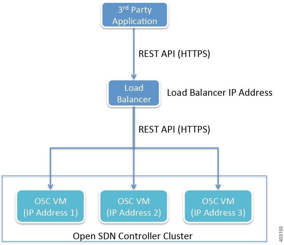
The following considerations need to be made when selecting the load balancer you want to use:
Once you have chosen a load balancer, refer to its documentation for information on how to configure it for use with the Open SDN Controller cluster. After you have done so, you will then need to register the IP address for each cluster node with the load balancer. Again, refer to the load balancer’s documentation for details.
Here are a few points to keep in mind when using a load balancer with a cluster:
-
When sending REST API requests, client applications will access the load balancer’s IP address (or Virtual IP address in HA deployments).
-
Open SDN Controller uses token-based authentication, where the initial HTTPS request uses basic authentication to obtain a token and all subsequent requests are sent with this token. This mechanism should be transparent to the load balancer.
-
Since Open SDN Controller utilizes a common cluster-wide token cache, a REST API request does not have any session affinity and can potentially be sent to a different cluster node.
-
The load balancer needs to be configured to pass through all HTTP methods (including the OPTIONS method).
-
The use of a load balancer will help prevent or minimize the impact of a denial-of-service (DoS) attack.
Installing Wireshark
-
Verify that your controller has an internet connection.
-
Download a local copy of the Wireshark source code:
-
Open the Wireshark download page - https://www.wireshark.org/download.html
-
From the Stable Release (1.12.4) section, click the Source Code link.
Ensure that you are downloading the tar file named wireshark-1.12.4.tar.bz2.
-
Enable read/write permissions to the tar file:
-
-
In the following procedure, note that <directory-1> is the local directory in which you downloaded the Wireshark source code and <directory-2> is the directory on the controller in which you placed a copy of the Wireshark source code.
| Step 1 | From an SSH
client, log into the controller, entering
sysadmin as the
username and
cisco as the
password.
The OS Configuration Console opens. | ||
| Step 2 | Select the Drop to shell option and then press Enter. | ||
| Step 3 | Stop the
iptables service:
sudo service iptables stop | ||
| Step 4 | Enter the
following commands to install the necessary libraries:
| ||
| Step 5 | Use either cURL
or SFTP to transfer the Wireshark source code to the controller.
(Via cURL) Open the cURL tool and enter the following command:
(Via SFTP) | ||
| Step 6 | Configure Wireshark on your controller: | ||
| Step 7 | Verify that
Wireshark installed successfully:
./tshark -G protocols | grep -i openflow The resulting output should look like this: OpenFlow openflow openflow OpenFlow 1.0 openflow_v1 openflow_v1 OpenFlow 1.3 openflow_v4 openflow_v4 OpenFlow 1.4 openflow_v5 openflow_v5 | ||
| Step 8 | Use Tshark
(terminal-based Wireshark) to capture packets on your controller.
For example, say you want to capture packets for interface eth0 and UDP port 1812. To do so, enter the following commands:
Note that the time it takes to complete this step varies, depending on the number of packets that need to be captured. | ||
| Step 9 | Start the
iptables service:
sudo service iptables start |
 Feedback