- Preface
-
- Introducing the Cisco SNS 3415 and Cisco SNS 3495 Hardware Appliances
- Preparing to Install the Cisco SNS 3415 and Cisco SNS 3495 Hardware Appliances
- Installing the Cisco SNS 3415 and Cisco SNS 3495 Hardware Appliances
- Installing and Configuring Cisco Secure Access Control System with Cisco SNS 3415 and Cisco SNS 3495 Appliances
-
- Introducing the Cisco SNS 3515 and Cisco SNS 3595 Hardware Appliances
- Preparing to Install the Cisco SNS 3515 and Cisco SNS 3595 Hardware Appliances
- Installing the Cisco SNS 3515 and Cisco SNS 3595 Hardware Appliances
- Installing and Configuring Cisco Secure Access Control System with Cisco SNS 3515 and Cisco SNS 3595 Appliances
Installation and Upgrade Guide for Cisco Secure Access Control System 5.8.1
Bias-Free Language
The documentation set for this product strives to use bias-free language. For the purposes of this documentation set, bias-free is defined as language that does not imply discrimination based on age, disability, gender, racial identity, ethnic identity, sexual orientation, socioeconomic status, and intersectionality. Exceptions may be present in the documentation due to language that is hardcoded in the user interfaces of the product software, language used based on RFP documentation, or language that is used by a referenced third-party product. Learn more about how Cisco is using Inclusive Language.
- Updated:
- March 22, 2016
Chapter: Installing the Cisco 1121 Secure Access Control System Hardware
Installing the Cisco 1121 Secure Access Control System Hardware
This chapter describes how to install your CSACS-1121 Series appliance and connect it to the network.
■![]() Rack-Mounting Configuration Guidelines
Rack-Mounting Configuration Guidelines
■![]() Mounting the CSACS-1121 Series Appliance in a 4-Post Rack
Mounting the CSACS-1121 Series Appliance in a 4-Post Rack
■![]() Powering Up the CSACS-1121 Series Appliance
Powering Up the CSACS-1121 Series Appliance
■![]() Preparing to Transport the Rack Cabinet
Preparing to Transport the Rack Cabinet
■![]() Removing or Replacing the CSACS-1121 Series Appliance
Removing or Replacing the CSACS-1121 Series Appliance
Before you begin the installation, read the Regulatory Compliance and Safety Information for the Cisco 1121 Secure Access Control System .
Warning: Only trained and qualified personnel should be allowed to install, replace, or service this equipment. Statement 1030![]()
Warning: This unit is intended for installation in restricted access areas. A restricted access area can be accessed only through the use of a special tool, lock and key, or other means of security.
Statement 1017![]()
Rack-Mounting Configuration Guidelines
Each CSACS-1121 Series appliance has a set of rack handles (installed at the factory). You will use these handles later when you install the appliance in a 4-post rack. You can front (flush) mount or mid-mount the appliance in a 19-inch (48.3-cm) equipment rack that conforms to the 4-post rack specification (the inside width of the rack should be 17.5 inches [44.45 cm]).
Mount the appliance in the brackets. When the appliance is installed in the rack, it requires one EIA 1.75-inch (4.4-cm) vertical mounting space or 1 rack unit (RU) for mounting.
Caution: You must leave clearance in the front and rear of the CSACS-1121 Series appliance, to allow cooling air to be drawn in through the front and circulated through the appliance and out the rear of the appliance.![]()
The Rack Installation Safety Guidelines and the following information will help you plan the equipment rack configuration:
■![]() When mounting an appliance in an equipment rack, ensure that the rack is bolted to the floor.
When mounting an appliance in an equipment rack, ensure that the rack is bolted to the floor.
■![]() Because you may install more than one appliance in the rack, ensure that the weight of all the appliances installed does not make the rack unstable.
Because you may install more than one appliance in the rack, ensure that the weight of all the appliances installed does not make the rack unstable.
Caution: Some equipment racks are also secured to ceiling brackets due to the weight of the equipment in the rack. If you use this type of installation, ensure that the rack you are using to install the appliances is secured to the building structure.![]()
■![]() As mentioned in Airflow Guidelines, maintain a 6-inch (15.2-cm) clearance at the front and rear of the appliance to ensure adequate air intake and exhaust.
As mentioned in Airflow Guidelines, maintain a 6-inch (15.2-cm) clearance at the front and rear of the appliance to ensure adequate air intake and exhaust.
■![]() Avoid installing appliances in an overly congested rack. Air flowing to or from other appliances in the rack might interfere with the normal flow of cooling air through the appliances, increasing the potential for overtemperature conditions within the appliances.
Avoid installing appliances in an overly congested rack. Air flowing to or from other appliances in the rack might interfere with the normal flow of cooling air through the appliances, increasing the potential for overtemperature conditions within the appliances.
■![]() Allow at least 24 inches (61 cm) of clearance at the front and rear of the rack for appliance maintenance.
Allow at least 24 inches (61 cm) of clearance at the front and rear of the rack for appliance maintenance.
Caution: To prevent appliance overheating, never install an appliance in an enclosed rack or a room that is not properly ventilated or air conditioned.![]()
■![]() Follow your local practices for cable management. Ensure that cables to and from appliances do not impede access for performing equipment maintenance or upgrades.
Follow your local practices for cable management. Ensure that cables to and from appliances do not impede access for performing equipment maintenance or upgrades.
Note: The rack-mount hardware kit does not include a 2-post equipment rack.
Mounting the CSACS-1121 Series Appliance in a 4-Post Rack
Warning: When the appliance is installed in a rack and is fully extended on its slide rail, it is possible for the rack to become unstable and tip over, which could cause serious injury. To eliminate the risk of rack instability from extending the rail or in the event of an earthquake, you should affix the rack to the floor.![]()
■![]() 4-Post Rack-Mount Hardware Kit
4-Post Rack-Mount Hardware Kit
■![]() Installing the Slide Rails in a Rack
Installing the Slide Rails in a Rack
■![]() Installing the Appliance into the Slide Rails
Installing the Appliance into the Slide Rails
4-Post Rack-Mount Hardware Kit
Figure 1 shows the items that you need to install the CSACS-1121 Series appliance in a 4-post rack.
Figure 1 Release Levers on the Slide Rail Hardware
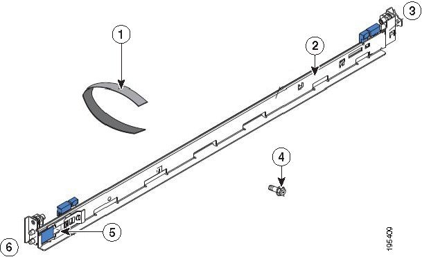
The following table describes the callouts in Figure 1.
|
|
|
||
|
|
|
||
|
|
|
Table 1 lists the contents of the rack-mount hardware kit (Cisco part number CSACS-1U-RAILS).
|
|
|
|---|---|
Installing the Slide Rails in a Rack
To install the CSACS-1121 Series appliance in a rack:
1.![]() Press on the rail-adjustment bracket on the rear of the slide rail (see Figure 2) to prevent the bracket from moving.
Press on the rail-adjustment bracket on the rear of the slide rail (see Figure 2) to prevent the bracket from moving.
2.![]() Press the adjustment tabs 1 and 2 (see Figure 2) and slide the rail-locking carrier toward the front of the slide rail until it snaps into place.
Press the adjustment tabs 1 and 2 (see Figure 2) and slide the rail-locking carrier toward the front of the slide rail until it snaps into place.
3.![]() Press the adjustment Tabs 1 and 2 and slide the rail-locking carrier toward the rear of the slide until it snaps into place.
Press the adjustment Tabs 1 and 2 and slide the rail-locking carrier toward the rear of the slide until it snaps into place.
Figure 2 Installing the Slide Rail into the Rack
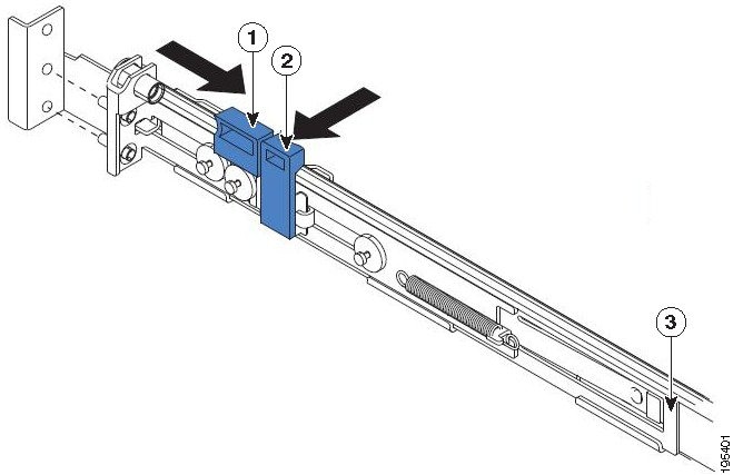
The following table describes the callouts in Figure 2.
|
|
|
||
|
|
|
If you need to adjust the slide-rail length, lift the release tab (see Figure 3) and fully extend the rail-adjustment bracket from the rear of the slide rail until it snaps into place.
4.![]() Align the pins on the rear rail-locking carrier with the holes on the rear mounting flange.
Align the pins on the rear rail-locking carrier with the holes on the rear mounting flange.
5.![]() Press the adjustment tab (see Figure 3) to secure the rear of the slide rail to the rear mounting flange.
Press the adjustment tab (see Figure 3) to secure the rear of the slide rail to the rear mounting flange.
Note: Ensure that the pins are fully extended through the mounting flange and slide rail.
Figure 3 Adjusting the Slide-rail Length
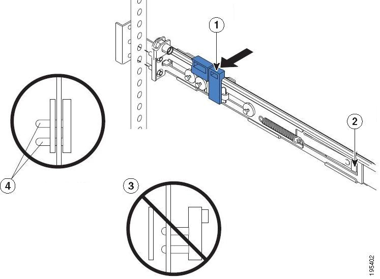
The following table describes the callouts in Figure 3.
|
|
|
Pins not extended through the mounting flange and slide rail |
|
|
|
|
6.![]() Align the pins (see Figure 4) on the front rail-locking carrier to the front mounting flange.
Align the pins (see Figure 4) on the front rail-locking carrier to the front mounting flange.
If you have adjusted the rail length, push the rail-locking carrier back toward the rear of the slide rail to align the slide rail with the mounting flange.
7.![]() Press the adjustment tab to secure the front of the slide rail to the front mounting flange.
Press the adjustment tab to secure the front of the slide rail to the front mounting flange.
Note: Ensure that the pins are fully extended through the mounting flange and the slide rail.
8.![]() Repeat these steps for the other slide rail.
Repeat these steps for the other slide rail.
Figure 4 Aligning the Slide Rail with the Mounting Flange
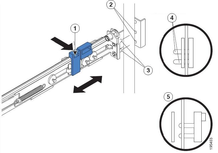
The following table describes the callouts in Figure 4.
|
|
|
||
|
|
|
Pins not extended through the mounting flange and slide rail |
|
|
|
|
Installing the Appliance into the Slide Rails
To install the CSACS-1121 Series appliance into the slide rails:
1.![]() Align the server on the slide rails and push it fully into the rack cabinet.
Align the server on the slide rails and push it fully into the rack cabinet.
2.![]() Secure the server to the front mounting flanges with the captive thumbscrews (see Figure 5).
Secure the server to the front mounting flanges with the captive thumbscrews (see Figure 5).
Note: You must leave the shipping brackets attached to the slide rails unless the shipping brackets impede the server from sliding fully into the rack cabinet. If you need to remove the shipping brackets, see Step 3.
Figure 5 Aligning the Server on the Slide Rails
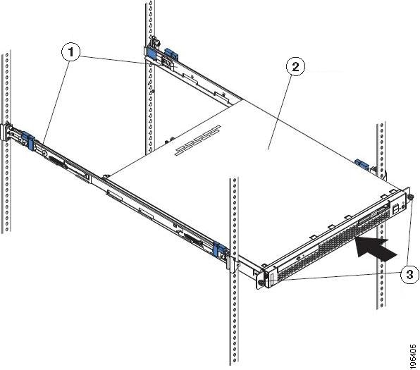
The following table describes the callouts in Figure 5.
|
|
|
||
|
|
|
3.![]() Press the release tab (see Figure 6) as indicated on the shipping bracket, and remove the shipping bracket from the slide rail.
Press the release tab (see Figure 6) as indicated on the shipping bracket, and remove the shipping bracket from the slide rail.
4.![]() Repeat step 3 for the other shipping bracket. Store the shipping brackets for future use.
Repeat step 3 for the other shipping bracket. Store the shipping brackets for future use.
Note: You must reinstall the shipping brackets on the slide rails before you transport the rack cabinet with the server installed. To reinstall the shipping brackets, reverse the steps.
Figure 6 Removing the Shipping Brackets
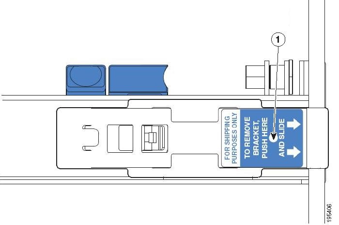
The following table describes the callout in Figure 6.
|
|
|
Connecting Cables
This section describes how to connect your CSACS-1121 Series appliance to the network and the appliance console. This section includes:
■![]() Connecting the Network Interface
Connecting the Network Interface
■![]() Connecting the Keyboard and Video Monitor
Connecting the Keyboard and Video Monitor
Figure 7 CSACS-1121 Series Appliance Rear View
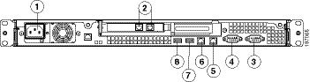
The following table describes the callouts in Figure 7.
|
|
|
||
|
|
|
||
|
|
|
||
|
|
|
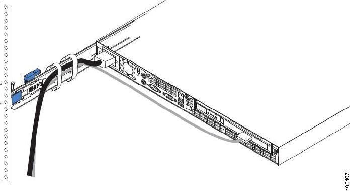
Attach cables (such as keyboard, monitor cables, if required) to the rear of the server. Route the cables to the left corner of the server (as viewed from the rear in Figure 8) and use the cable straps to secure the cables to the slide rails.
Figure 8 Connecting the Cables
Connecting the Network Interface
Warning: Do not work on the system or connect or disconnect cables during periods of lightning activity. Statement 1001![]()
This section describes how to connect the CSACS-1121 Series appliance Ethernet port.
The Ethernet connector supports Serial over LAN (SOL) cables. The RJ-45 port supports standard straight-through and crossover Category 5 unshielded twisted-pair (UTP) cables. Cisco does not supply Category 5 UTP cables; these cables are available commercially.
To connect the cable to the appliance Ethernet port:
1.![]() Verify that the appliance is turned off.
Verify that the appliance is turned off.
2.![]() Connect one end of the cable to the GigabitEthernet 0 port on the appliance.
Connect one end of the cable to the GigabitEthernet 0 port on the appliance.
3.![]() Connect the other end to a switch in your network.
Connect the other end to a switch in your network.
Ethernet Port Connector
The CSACS 1121 Series appliance has two integrated dual-port Ethernet controllers. The SNS-3400 series appliance has four integrated dual-port Ethernet controllers. ACS supports multiple NICs. See Multiple Network Interface Connectors for more information. These controllers provide an interface for connecting to 10-Mb/s, 100-Mb/s, or 1000-Mb/s networks and provide full-duplex (FDX) capability, which enables simultaneous transmission and reception of data on the Ethernet LAN.
To access the Ethernet port, connect a Category 3, 4, 5, 5E, or 6 unshielded twisted-pair (UTP) cable to the RJ-45 connector on the back of the appliance.
Table 2 describes the UTP cable Categories.
|
|
|
|---|---|
EIA Categories 3, 4, or 5 UTP (2 or 4 pair) up to 328 ft (100 m) |
|
EIA Category 6 UTP (recommended), Category 5E UTP or 5 UTP (2 pair) up to 328 ft (100 m) |
Figure 9 shows the Ethernet RJ-45 port and plug.
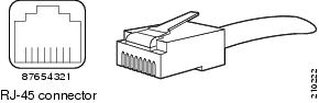
Table 3 lists and describes the RJ-45 pin signals used on the connector.
|
|
|
|
|---|---|---|
Multiple Network Interface Connectors
ACS 5.8.1 with the Cisco SNS 3500 or Cisco SNS 3400, Virtual machine, or CSACS-1121 platform allows you to use up to six network interfaces: Ethernet 0, Ethernet 1, Ethernet 2, Ethernet 3, Ethernet 4, and Ethernet 5.
Note: To avoid system failures, you must ensure that Ethernet interface 0 is up and running successfully.
Table 4 lists the ACS 5.8.1 services that are distributed among the network interfaces.
|
|
|
|---|---|
ACS management functions use only Ethernet interface 0, whereas authentication, authorization, and accounting (AAA) protocols use all of the configured network interfaces. You must connect the ACS nodes in the distributed deployment only to Ethernet 0. The syslog messages are sent and received at the log collector’s Ethernet 0 interface. Data forwarding from one interface to another interface is prohibited to prevent potential security issues. The external identity stores are supported only on Ethernet interface 0. In ACS 5.8.1, multiple network interface connectors are also supported for the RADIUS and TACACS+ proxy functionalities.
Cisco recommends you to use IP address from different subnets for different interfaces in ACS. If you use IP address from same subnet for different interfaces in ACS, it results in ACS to send ARP replies with same MAC address for the IP addresses from the same subnet. This recommendation is not applicable for NIC bonding feature. The CLI and ACS management interfaces are accessible from both Ethernet 0 and Ethernet 1 interfaces if you configure both the Ethernet 0 and Ethernet 1 interfaces with IP addresses from the same subnet. Therefore, the IP addresses for the Ethernet 0 and Ethernet 1 interfaces should be from different subnets to restrict accessing ACS (CLI and ACS Web interface) only using Ethernet interface 0.
Configuring Multiple Network Interfaces
By default, Ethernet interface 0 takes the IP address that is assigned for ACS. However, for the other Ethernet ports, you must configure the IP address manually.
To configure the IP address for Ethernet ports, complete the following steps:
1.![]() Log in to the ACS CLI using the CLI username and password.
Log in to the ACS CLI using the CLI username and password.
2.![]() Enter config t to enter configuration mode of the ACS CLI.
Enter config t to enter configuration mode of the ACS CLI.
3.![]() Enter the interface GigabitEthernet number command.
Enter the interface GigabitEthernet number command.
4.![]() Enter the no shutdown command to bring up the interface.
Enter the no shutdown command to bring up the interface.
5.![]() Enter the ip address ip address subnet mask command.
Enter the ip address ip address subnet mask command.
The console displays the following message:
Changing the IP may result in undesired side effects on any installed application(s).
Are you sure you want to proceed? Y/N [N]:
The specified interface is configured with the given IP address.
ACS restarts automatically. Wait for some time to ensure that all the processes are up and running successfully.
In an IPv6-enabled network, the Ethernet interface 0 can work as a dual-stack interface, but configuring an IPv4 address is mandatory. The Ethernet interfaces other than Ethernet 0 use an IPv6 address or an IPv4 address or both of them. If you want to use an IPv4 address for the other Ethernet ports, you must configure IPv4 addresses using the ip address Ipv4 address ip-mask command as described above.
Note: ACS 5.8.1 supports IPv4 and IPv6 dual-stack networking but does not support pure IPv6 network.
Bonding Ethernet Interfaces
ACS supports bonding of two physical interfaces into a single virtual interface. This feature is called Network Interface Card (NIC) Bonding. This bonding of two physical interfaces into one virtual interface helps ACS process access requests when one of the two interfaces go down. When one physical interface in the bond goes down, the other physical interface in the same bond works as a backup for the other one and processes all the requests that come to this bonding. The NIC Bonding feature in ACS provides only a backup of one physical interface when the other interface is down. The other general features of NIC bonding, such as load balancing, are not supported. In ACS 5.8.1, with six Ethernet interfaces being available, you can create three bonds.
Guidelines for creating NIC bonding in ACS:
■![]() Bond 0—You can combine Ethernet interface 0 and Ethernet interface 1 to make bond 0. Ethernet interfaces 0 and 1 act as slaves of bond 0. For bond 0, Ethernet interface 0 is the primary slave, and Ethernet interface 1 is the secondary slave. Therefore, when Ethernet interface 0 goes down, Ethernet interface 1 acts as a backup for Ethernet interface 0 and processes all requests. Ethernet interface 1 cannot be the primary slave in bond 0. Bond 0 takes the IP address of Ethernet interface 0 and removes the IP address of Ethernet interface 1. Bond 0 takes the MAC address of Ethernet interface 0 and assigns the same to Ethernet interface 1.
Bond 0—You can combine Ethernet interface 0 and Ethernet interface 1 to make bond 0. Ethernet interfaces 0 and 1 act as slaves of bond 0. For bond 0, Ethernet interface 0 is the primary slave, and Ethernet interface 1 is the secondary slave. Therefore, when Ethernet interface 0 goes down, Ethernet interface 1 acts as a backup for Ethernet interface 0 and processes all requests. Ethernet interface 1 cannot be the primary slave in bond 0. Bond 0 takes the IP address of Ethernet interface 0 and removes the IP address of Ethernet interface 1. Bond 0 takes the MAC address of Ethernet interface 0 and assigns the same to Ethernet interface 1.
■![]() Bond 1—You can combine Ethernet interface 2 and Ethernet interface 3 to make bond 1. Ethernet interfaces 2and 3 act as slaves of bond 1. For bond 1, Ethernet interface 2 is the primary slave, and Ethernet interface 3 is the secondary slave. Therefore, when Ethernet interface 2 goes down, Ethernet interface 3 acts as a backup for Ethernet interface 2 and processes all requests. Ethernet interface 3 cannot be the primary slave in bond 1. Bond 1 takes the IP address of Ethernet interface 2 and removes the IP address of Ethernet interface 3. Bond 1 takes the MAC address of Ethernet interface 2 and assigns the same to Ethernet interface 3.
Bond 1—You can combine Ethernet interface 2 and Ethernet interface 3 to make bond 1. Ethernet interfaces 2and 3 act as slaves of bond 1. For bond 1, Ethernet interface 2 is the primary slave, and Ethernet interface 3 is the secondary slave. Therefore, when Ethernet interface 2 goes down, Ethernet interface 3 acts as a backup for Ethernet interface 2 and processes all requests. Ethernet interface 3 cannot be the primary slave in bond 1. Bond 1 takes the IP address of Ethernet interface 2 and removes the IP address of Ethernet interface 3. Bond 1 takes the MAC address of Ethernet interface 2 and assigns the same to Ethernet interface 3.
■![]() Bond 2—You can combine Ethernet interface 4 and Ethernet interface 5 to make bond 2. Ethernet interfaces 4 and 5 act as slaves of bond 2. For bond 2, Ethernet interface 4 is the primary slave, and Ethernet interface 5 is the secondary slave. Therefore, when Ethernet interface 4 goes down, Ethernet interface 5 acts as a backup for Ethernet interface 4 and processes all requests. Ethernet interface 5 cannot be the primary slave in bond 2. Bond 2 takes the IP address of Ethernet interface 4 and removes the IP address of Ethernet interface 5. Bond 2 takes the MAC address of Ethernet interface 4 and assigns the same to Ethernet interface 5.
Bond 2—You can combine Ethernet interface 4 and Ethernet interface 5 to make bond 2. Ethernet interfaces 4 and 5 act as slaves of bond 2. For bond 2, Ethernet interface 4 is the primary slave, and Ethernet interface 5 is the secondary slave. Therefore, when Ethernet interface 4 goes down, Ethernet interface 5 acts as a backup for Ethernet interface 4 and processes all requests. Ethernet interface 5 cannot be the primary slave in bond 2. Bond 2 takes the IP address of Ethernet interface 4 and removes the IP address of Ethernet interface 5. Bond 2 takes the MAC address of Ethernet interface 4 and assigns the same to Ethernet interface 5.
■![]() ACS can have only three bonds, bond 0, bond 1, and bond 2, as stated above. You cannot bond interfaces 1 and 2, 3 and 4, and 1 and 5, together. It is not possible to make the Ethernet 2 or Ethernet 3 interfaces a backup interface for Ethernet 0 and so on.
ACS can have only three bonds, bond 0, bond 1, and bond 2, as stated above. You cannot bond interfaces 1 and 2, 3 and 4, and 1 and 5, together. It is not possible to make the Ethernet 2 or Ethernet 3 interfaces a backup interface for Ethernet 0 and so on.
■![]() Within a single bond, the two physical Ethernet interfaces that are involved should be from the same subnet. You cannot create interface bonding with Ethernet interfaces from different subnets. Ethernet interface 0 should be assigned an IPv4 address before creating bond 0. Similarly, you cannot create bond 1 without an IPv4 or IPv6 address assigned to Ethernet 2 interface.
Within a single bond, the two physical Ethernet interfaces that are involved should be from the same subnet. You cannot create interface bonding with Ethernet interfaces from different subnets. Ethernet interface 0 should be assigned an IPv4 address before creating bond 0. Similarly, you cannot create bond 1 without an IPv4 or IPv6 address assigned to Ethernet 2 interface.
■![]() Ethernet interface 0 acts as both the management interface and the runtime interface, whereas the other interfaces act as runtime interfaces. In ACS, you can create bond 0 and leave the other Ethernet interfaces as is. In this case, bond 0 acts as a manangement and runtime interface, and other Ethernet interfaces act as runtime interfaces. If you create three bonds, bond 0, bond 1, and bond 2, bond 0 acts as a management and runtime interface, and bond 1 and bond 2 act as a runtime interfaces.
Ethernet interface 0 acts as both the management interface and the runtime interface, whereas the other interfaces act as runtime interfaces. In ACS, you can create bond 0 and leave the other Ethernet interfaces as is. In this case, bond 0 acts as a manangement and runtime interface, and other Ethernet interfaces act as runtime interfaces. If you create three bonds, bond 0, bond 1, and bond 2, bond 0 acts as a management and runtime interface, and bond 1 and bond 2 act as a runtime interfaces.
■![]() You can change the IP address of the primary slave interface in a bonding. The new IP address is assigned to the bonding interface because bonding takes the IP address of the primary slave.
You can change the IP address of the primary slave interface in a bonding. The new IP address is assigned to the bonding interface because bonding takes the IP address of the primary slave.
■![]() When you break the interface bonding, the IP address assigned to the bonding interface is assigned back to the primary slave interface. The secondary slave will be down without any IP address. You must manually configure an IP address for the secondary slave.
When you break the interface bonding, the IP address assigned to the bonding interface is assigned back to the primary slave interface. The secondary slave will be down without any IP address. You must manually configure an IP address for the secondary slave.
■![]() If you want to configure interface bonding to an ACS instance in a distributed deployment, deregister the ACS instance from the deployment, configure interface bonding, and then register the ACS instance back to the deployment.
If you want to configure interface bonding to an ACS instance in a distributed deployment, deregister the ACS instance from the deployment, configure interface bonding, and then register the ACS instance back to the deployment.
■![]() Use the show running-config and show interface commands to see the bonding interface information.
Use the show running-config and show interface commands to see the bonding interface information.
Configuring Interface Bonding
To create bond 0, complete the following steps:
1.![]() Log in to the ACS CLI using the CLI username and password.
Log in to the ACS CLI using the CLI username and password.
2.![]() Enter config t to enter configuration mode.
Enter config t to enter configuration mode.
3.![]() Enter the interface GigabitEthernet 0 command.
Enter the interface GigabitEthernet 0 command.
4.![]() Enter the no shutdown command to bring up the interface up.
Enter the no shutdown command to bring up the interface up.
5.![]() Enter the backup interface GibabitEthernet 1 command.
Enter the backup interface GibabitEthernet 1 command.
The console displays the following message:
WARN: IP address of interface eth1 will be removed once NIC bonding is enabled.
Configuring backup interface may result in undesired side effects on any installed application(s).
Are you sure you want to proceed? Y/N [N]:
The console displays the following message:
ACS restarts automatically. Wait for some time to ensure that all processes are up and running successfully.
To create bond 1, complete the following steps:
1.![]() Log in to the ACS CLI using the CLI username and password.
Log in to the ACS CLI using the CLI username and password.
2.![]() Enter config t to enter configuration mode.
Enter config t to enter configuration mode.
3.![]() Enter the interface GigabitEthernet 2 command.
Enter the interface GigabitEthernet 2 command.
4.![]() Enter the no shutdown command to bring up the interface.
Enter the no shutdown command to bring up the interface.
5.![]() Enter the backup interface GigabitEthernet 3 command.
Enter the backup interface GigabitEthernet 3 command.
The console displays the following message:
WARN: IP address of interface eth3 will be removed once NIC bonding is enabled.
Configuring backup interface may result in undesired side effects on any installed application(s).
Are you sure you want to proceed? Y/N [N]:
The console displays the following message:
ACS restarts automatically. Wait for some time to ensure that all processes are up and running successfully.
To create bond 2, complete the following steps:
1.![]() Log in to the ACS CLI using the CLI username and password.
Log in to the ACS CLI using the CLI username and password.
2.![]() Enter config t to enter configuration mode.
Enter config t to enter configuration mode.
3.![]() Enter the interface GigabitEthernet 4 command.
Enter the interface GigabitEthernet 4 command.
4.![]() Enter the no shutdown command to bring up the interface.
Enter the no shutdown command to bring up the interface.
5.![]() Enter the backup interface GigabitEthernet 5 command.
Enter the backup interface GigabitEthernet 5 command.
The console displays the following message:
WARN: IP address of interface eth5 will be removed once NIC bonding is enabled.
Configuring backup interface may result in undesired side effects on any installed application(s).
Are you sure you want to proceed? Y/N [N]:
The console displays the following message:
ACS restarts automatically. Wait for some time to ensure that all processes are up and running successfully.
Removing NIC Bond
Use the no form of the backup interface command to remove NIC bonding from ACS.
To remove bond 0, complete the following steps:
1.![]() Log in to ACS CLI using the CLI username and password.
Log in to ACS CLI using the CLI username and password.
2.![]() Enter config t to enter configuration mode.
Enter config t to enter configuration mode.
3.![]() Enter the interface GigabitEthernet 0 command.
Enter the interface GigabitEthernet 0 command.
4.![]() Enter the no backup interface GigabitEthernet 1 command.
Enter the no backup interface GigabitEthernet 1 command.
The console displays the following message:
Removing backup interface configuration may result in undesired side effects on any installed application(s).
Are you sure you want to proceed? Y/N [N]:
The console displays the following message:
ACS restarts automatically. Wait for some time to ensure that all processes are up and running successfully.
To remove bond 1, complete the following steps:
1.![]() Log in to ACS CLI using the CLI username and password.
Log in to ACS CLI using the CLI username and password.
2.![]() Enter config t to enter configuration mode.
Enter config t to enter configuration mode.
3.![]() Enter the interface GigabitEthernet 2 command.
Enter the interface GigabitEthernet 2 command.
4.![]() Enter the no backup interface GigabitEthernet 3 command.
Enter the no backup interface GigabitEthernet 3 command.
The console displays the following message:
Removing backup interface configuration may result in undesired side effects on any installed application(s).
Are you sure you want to proceed? Y/N [N]:
The console displays the following message:
ACS restarts automatically. Wait for some time to ensure that all processes are up and running successfully.
To remove bond 2, complete the following steps:
1.![]() Log in to ACS CLI using the CLI username and password.
Log in to ACS CLI using the CLI username and password.
2.![]() Enter config t to enter configuration mode.
Enter config t to enter configuration mode.
3.![]() Enter the interface GigabitEthernet 4 command.
Enter the interface GigabitEthernet 4 command.
4.![]() Enter the no backup interface GigabitEthernet 5 command.
Enter the no backup interface GigabitEthernet 5 command.
The console displays the following message:
Removing backup interface configuration may result in undesired side effects on any installed application(s).
Are you sure you want to proceed? Y/N [N]:
The console displays the following message:
ACS restarts automatically. Wait for some time to ensure that all processes are up and running successfully.
Connecting the Console
Warning: Do not work on the system or connect or disconnect cables during periods of lightning activity. Statement 1001![]()
Your CSACS-1121 Series appliance has a DCE-mode console port for connecting a console terminal to your appliance. The appliance uses a DB-9 serial connector for the console port.
The console port on the CSACS-1121 Series appliance includes an EIA/TIA-232 asynchronous serial (DB-9) connector. This serial console connector (port) allows you to access the appliance locally by connecting a terminal—either a PC running terminal-emulation software or an ASCII terminal—to the console port.
To connect a PC running terminal-emulation software to the console port, use a DB-9 female to DB-9 female straight-through cable.
To connect an ASCII terminal to the console port, use a DB-9 female to DB-25 male straight-through cable with a DB-25 female to DB-25 female gender changer.
To connect a terminal or a PC running terminal-emulation software to the console port on the CSACS-1121 Series appliance:
1.![]() Connect the terminal using a straight-through cable to the console port.
Connect the terminal using a straight-through cable to the console port.
2.![]() Configure your terminal or terminal-emulation software for 9600 baud, 8 data bits, no parity, 1 stop bit, and no hardware flow control.
Configure your terminal or terminal-emulation software for 9600 baud, 8 data bits, no parity, 1 stop bit, and no hardware flow control.
Serial (Console) Port Connector
The CSACS 1121 Series appliance has one serial port connector located on the back panel of the appliance.
Figure 10 shows the pin number assignments for the 9-pin, male D-shell serial port connector located on the back panel of the appliance. These pin number assignments are those defined for RS-232-C and conform to industry standards.
Figure 10 Serial Port Connector
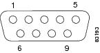
Table 5 lists and describes the serial (console) port pin-out.
|
|
|
|
|---|---|---|
Connecting the Keyboard and Video Monitor
Warning: Do not work on the system or connect or disconnect cables during periods of lightning activity. Statement 1001![]()
This section describes how to connect a keyboard and video monitor to the CSACS-1121 Series appliance.
As an alternative to the keyboard and video monitor, you can use a serial console to connect to the CSACS-1121 appliance.
The CSACS-1121 appliance does not provide support for a mouse.
The CSACS-1121 provides USB ports on the front and rear of the appliance that can be used to connect a keyboard and video monitor.
To connect a keyboard and video monitor to the appliance:
1.![]() Verify that the appliance is turned off.
Verify that the appliance is turned off.
2.![]() Connect the end of the keyboard cable to the PS/2 (keyboard) port which is located on the back panel of the appliance.
Connect the end of the keyboard cable to the PS/2 (keyboard) port which is located on the back panel of the appliance.
3.![]() Connect the end of the video monitor cable to the PS/2 (video monitor) port which is located on the back panel of the appliance.
Connect the end of the video monitor cable to the PS/2 (video monitor) port which is located on the back panel of the appliance.
Cable Management
Cable management is the most visual aspect of your appliance setup. However, cable management is often overlooked because it can be time consuming.
Equipment racks and enclosures house more equipment today than ever before. This growth has increased the need for organized cable management both inside and outside the rack. Poor cable management not only leads to damaged cables or increased time for adding or changing cables, but also blocks critical airflow or access. These problems can lead to inefficiencies in the performance of your equipment or even downtime.
There are many solutions to address cable management. They can range from simple cable management rings, to vertical or horizontal organizers, to troughs and ladders.
All CSACS-1121 Series appliance cables should be properly dressed so as not to interfere with each other or other pieces of equipment. Use local practices to ensure that the cables attached to your appliance are properly dressed.
Proceed to the next section, Powering Up the CSACS-1121 Series Appliance, to continue the installation process.
Powering Up the CSACS-1121 Series Appliance
Warning: Do not touch the power supply when the power cord is connected. For systems with a power switch, line voltages are present within the power supply even when the power switch is off and the power cord is connected. For systems without a power switch, line voltages are present within the power supply when the power cord is connected. Statement 4![]()
Warning: This equipment is intended to be grounded. Ensure that the host is connected to earth ground during normal use. Statement 39![]()
Checklist for Power Up
You are ready to power up the CSACS-1121 Series appliance if:
■![]() The appliance is securely mounted.
The appliance is securely mounted.
■![]() Power, network, and interface cables are properly connected.
Power, network, and interface cables are properly connected.
Power-Up Procedure
To power up the CSACS-1121 Series appliance and verify its initialization and self-test, follow this procedure. When the procedure is completed, the appliance is ready to be configured.
1.![]() Review the information in Safety Guidelines.
Review the information in Safety Guidelines.
2.![]() Plug the AC power cord into the power cord receptacle at the rear of the appliance. (See location 1 in Figure 7.)
Plug the AC power cord into the power cord receptacle at the rear of the appliance. (See location 1 in Figure 7.)
3.![]() Connect the other end of the power cord to a power source at your installation site.
Connect the other end of the power cord to a power source at your installation site.
4.![]() Press the power button on the front of the appliance. (See location 2 in Figure 11.)
Press the power button on the front of the appliance. (See location 2 in Figure 11.)
The appliance should begin booting. After the operating system boots, you are ready to initialize the basic software configuration. For configuration procedures, see the software installation guide or user guide.
Figure 11 CSACS-1121 Series Appliance Front View
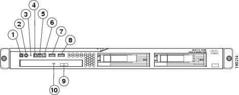
The following table describes the callouts in Figure 11.
|
|
|
||
|
|
|
||
|
|
|
||
|
|
|
||
|
|
|
Checking the LEDs
When the CSACS-1121 Series appliance is up and running, observe the front-panel LEDs. The following LEDs provide power, activity, and status information:
CSACS-1121 Appliance Front-Panel LEDs
–![]() Off when power is off or an error condition has been detected in the operating voltages.
Off when power is off or an error condition has been detected in the operating voltages.
–![]() On when appliance software has booted up and the appliance is operational.
On when appliance software has booted up and the appliance is operational.
–![]() Off when appliance has not yet booted or an error condition has been detected in the boot process.
Off when appliance has not yet booted or an error condition has been detected in the boot process.
For more detailed information about the LEDs, see Troubleshooting.
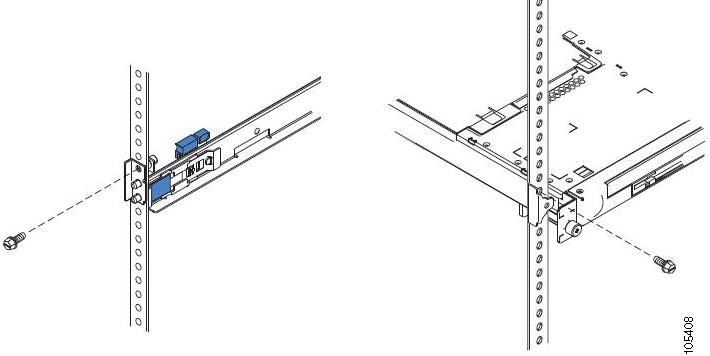
Preparing to Transport the Rack Cabinet
To transport the CSACS-1121 Series appliance to another location with the server installed:
1.![]() Remove the large screw (see Figure 12) and discard it.
Remove the large screw (see Figure 12) and discard it.
2.![]() Remove and save the front screw.
Remove and save the front screw.
3.![]() Loosen the other two rear screws.
Loosen the other two rear screws.
4.![]() Fully extend the rail and insert the screw you saved into the position where the large screw had been located.
Fully extend the rail and insert the screw you saved into the position where the large screw had been located.
5.![]() Tighten all screws to secure the rail.
Tighten all screws to secure the rail.
6.![]() Repeat the steps from Remove the large screw (see Figure 12 on page 19) and discard it. to Tighten all screws to secure the rail. for the other rail.
Repeat the steps from Remove the large screw (see Figure 12 on page 19) and discard it. to Tighten all screws to secure the rail. for the other rail.
Figure 12 Preparing to Transport the Rack Cabinet
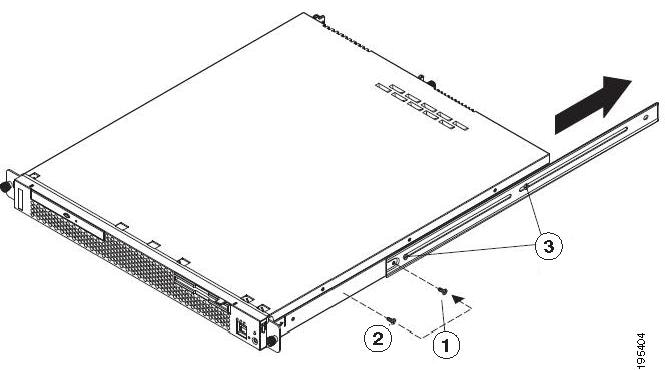
The following table describes the callouts in Figure 12.
|
|
|
||
|
|
|
7.![]() You must secure the server to the rack, by doing the following:
You must secure the server to the rack, by doing the following:
a.![]() If necessary, disconnect the cables from the rear of the server.
If necessary, disconnect the cables from the rear of the server.
b.![]() Slide the server out of the rack 150 mm (6 inches) and insert the M6 screws in each slide rail.
Slide the server out of the rack 150 mm (6 inches) and insert the M6 screws in each slide rail.
c.![]() Secure the server to the rack cabinet with the M6 screws. See Figure 13.Preparing to Move the Rack Cabinet to Another LocationPreparing to Move the Rack Cabinet to Another Location
Secure the server to the rack cabinet with the M6 screws. See Figure 13.Preparing to Move the Rack Cabinet to Another LocationPreparing to Move the Rack Cabinet to Another Location
8.![]() Ensure that the rails are fully extended to the rear of the rack cabinet.
Ensure that the rails are fully extended to the rear of the rack cabinet.
If you have removed the shipping brackets on the slide rails, you must reinstall them before you transport the rack cabinet with the server installed. Reverse the instructions on the shipping bracket to reinstall it, as shown in Figure 6.
Figure 13 Preparing to Move the Rack Cabinet to Another Location
Removing or Replacing the CSACS-1121 Series Appliance
Warning: Before working on a system that has an On/Off switch, turn OFF the power and unplug the power cord. Statement 1![]()
Warning: Ultimate disposal of this product should be handled according to all national laws and regulations. Statement 1040![]()
■![]() Removing a CSACS-1121 Series Appliance
Removing a CSACS-1121 Series Appliance
■![]() Replacing a CSACS-1121 Series Appliance
Replacing a CSACS-1121 Series Appliance
Removing a CSACS-1121 Series Appliance
To remove a CSACS-1121 Series appliance from your network:
2.![]() Disconnect the power cords and network cables.
Disconnect the power cords and network cables.
3.![]() Physically remove the appliance from the rack.
Physically remove the appliance from the rack.
The appliance is in constant communication on your network; thus, when the network notices that the appliance is no longer responding to it, the network stops sending requests to the appliance. This change is visible to users.
Note: If other appliances are attached to the network, the network continues sending requests to the other appliances.
Replacing a CSACS-1121 Series Appliance
1.![]() Remove the appliance from the network.
Remove the appliance from the network.
2.![]() Install a new appliance using the same installation procedures that you used for the previous appliance.
Install a new appliance using the same installation procedures that you used for the previous appliance.
3.![]() Configure the new appliance using the same configuration parameters that you used for the removed appliance.
Configure the new appliance using the same configuration parameters that you used for the removed appliance.
 Feedback