- Preface
- Chapter 1 - Broadband Access Center Overview
- Chapter 2 - Broadband Access Center Architecture
- Chapter 3 - Configuration Workflows and Checklists
- Chapter 4 - DOCSIS Configuration
- Chapter 5 - PacketCable Voice Configuration
- Chapter 6 - Troubleshooting PacketCable eMTA Provisioning
- Chapter 7 - CableHome Configuration
- Chapter 8 - Configuration Templates Management
- Chapter 9 - Understanding the Administrator User Interface
- Chapter 10 - Using the Administrator User Interface
- Chapter 11 - Configuring Broadband Access Center
- Chapter 12 - Configuring and Using the Sample User Interface
- Chapter 13 - Support Tools and Advanced Concepts
- Chapter 14 - Database Management
- Appendix A - Alert and Error Messages
- Appendix B - PacketCable DHCP Options to BAC Properties Mapping
- Appendix C - API Use Cases
- Glossary
- Index
Cisco Broadband Access Center Administrator Guide, Release 2.7.1
Bias-Free Language
The documentation set for this product strives to use bias-free language. For the purposes of this documentation set, bias-free is defined as language that does not imply discrimination based on age, disability, gender, racial identity, ethnic identity, sexual orientation, socioeconomic status, and intersectionality. Exceptions may be present in the documentation due to language that is hardcoded in the user interfaces of the product software, language used based on RFP documentation, or language that is used by a referenced third-party product. Learn more about how Cisco is using Inclusive Language.
- Updated:
- September 14, 2007
Chapter: Chapter 11 - Configuring Broadband Access Center
- Configuring Class of Service
- Configuring Custom Properties
- Configuring Defaults
- Configuring DHCP Criteria
- Managing External Files
- Managing License Keys
- Managing RDU Extensions
- Publishing Provisioning Data
- Configuring SRV Records in the Network Registrar DNS Server
- Configuring SNMPv3 Cloning on the RDU and DPE for
Secure Communication with PacketCable MTAs - Automatic FQDN Generation
Configuring Broadband Access Center
This chapter describes the Broadband Access Center (BAC) configuration tasks that you perform by selecting the options in the Configuration menu:
•![]() Configuring Custom Properties
Configuring Custom Properties
•![]() Configuring SRV Records in the Network Registrar DNS Server
Configuring SRV Records in the Network Registrar DNS Server
•![]() Configuring SNMPv3 Cloning on the RDU and DPE for Secure Communication with PacketCable MTAs
Configuring SNMPv3 Cloning on the RDU and DPE for Secure Communication with PacketCable MTAs
Configuring Class of Service
By using the BAC administrator user interface, you can configure the Class of Service offered to your customers. For example, you can associate DOCSIS options with different DOCSIS Class of Service. You use the BAC administrator user interface to add, modify, view, or delete any selected
Class of Service.
Figure 11-1 describes the Manage Class of Service page.
Figure 11-1 Manage Class of Service Page
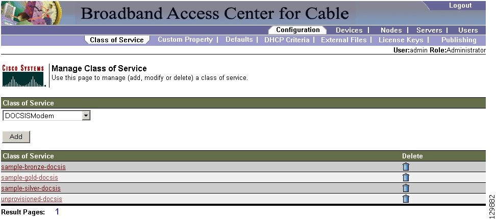
Table 11-1 identifies the fields and buttons shown in Figure 11-1.
|
|
|
|---|---|
|
|
|
Class of Service |
A drop-down list that identifies the technology Class of Service that you can search for. Available options are: • • • • • • • Note |
Add |
Lets you add a new Class of Service. |
Class of Service list |
Displays the names of Class of Service objects. |
Delete |
Lets you delete the selected Class of Service. |
Adding a Class of Service
To add a specific Class of Service:
Step 1 ![]() Choose Configuration > Class of Service.
Choose Configuration > Class of Service.
Step 2 ![]() Click Add. The Add Class of Service page appears. This page identifies the various settings for the selected Class of Service.
Click Add. The Add Class of Service page appears. This page identifies the various settings for the selected Class of Service.
Step 3 ![]() Enter the name of your new Class of Service.
Enter the name of your new Class of Service.
Step 4 ![]() Choose a Class of Service Type.
Choose a Class of Service Type.
For example, assume that you want to create a new Class of Service called Gold-Classic for DOCSIS modems. You might enter Gold-Classic as the Class of Service Name, and choose DOCSIS from the service type drop-down list.
Step 5 ![]() Enter a Property Name and Property Value in the appropriate fields.
Enter a Property Name and Property Value in the appropriate fields.
For example, choose as the property name /cos/docsis/file. Enter Gold-Classic.cm in the Property Value field, and continue with the rest of this procedure.
Multiple Property Name:Property Value pairs could appear on this page. You use the Delete button to remove any unwanted pairs from the Class of Service.

Note ![]() When adding a DOCSISModem Class of Service, you must specify the
When adding a DOCSISModem Class of Service, you must specify the /cos/docsis/file property with the value being the name of a previously added external file. This file is used when provisioning a DOCSIS device that has this Class of Service.
BAC provides automatic selection of a cable modem configuration file that enables the highest DOCSIS version compatible with the modem. To enable this feature, you must configure the Class of Service with multiple configuration files, one for each DOCSIS level. Use the following properties to allow the selection of a configuration file specific to a DOCSIS version:
•![]()
/cos/docsis/file/1.0—Selects a configuration file specific to DOCSIS 1.0.
•![]()
/cos/docsis/file/1.1—Selects a configuration file specific to DOCSIS 1.1.
•![]()
/cos/docsis/file/2.0—Selects a configuration file specific to DOCSIS 2.0.
When adding a PacketCable Class of Service, you must specify the /cos/packetCableMTA/file property with the value being the name of a previously added external file. This file is used when provisioning a PacketCable device that has this Class of Service.
When adding a CableHome WAN-MAN Class of Service, you must specify the /cos/cableHomeWanMan/file property with the value being the name of a previously added external file. This file is used when provisioning a CableHome WAN-MAN device that has this Class of Service.
Step 6 ![]() Click Add to add the property to the defining Class of Service.
Click Add to add the property to the defining Class of Service.
Step 7 ![]() Click Submit to finalize the process or Reset to return all fields to their previous setting.
Click Submit to finalize the process or Reset to return all fields to their previous setting.
After submitting the Class of Service, the Manage Class of Service page appears to show the newly added Class of Service for that particular device type.
Modifying a Class of Service
You modify your Class of Service by selecting the various properties and assigning appropriate property values. When creating a Class of Service for the first time you must select all the required properties and assign values to them. If you make a mistake, or your business requirements for a certain Class of Service change, you can either change the property value before submitting your previous changes or delete the Property Name:Property Value pair altogether.
Note ![]() Changes to the Class of Service object trigger the Configuration Regeneration Service (CRS) to regenerate configurations for all affected devices and send configurations to the DPEs. The CRS performs this task as a background job.
Changes to the Class of Service object trigger the Configuration Regeneration Service (CRS) to regenerate configurations for all affected devices and send configurations to the DPEs. The CRS performs this task as a background job.
You can view the status of the CRS from the View RDU Details page.
To add, delete, or modify Class of Service properties:
Step 1 ![]() Choose Configuration > Class of Service.
Choose Configuration > Class of Service.
Step 2 ![]() Choose the Class of Service to be modified.
Choose the Class of Service to be modified.
Step 3 ![]() Click the link corresponding to the correct Class of Service. The Modify Class of Service page appears; note that the selected Class of Service name and type appear below the page description.
Click the link corresponding to the correct Class of Service. The Modify Class of Service page appears; note that the selected Class of Service name and type appear below the page description.
•![]() To add a new property to the selected Class of Service:
To add a new property to the selected Class of Service:
–![]() Select the first property that you want assigned to the selected Class of Service, from the Property Name drop-down list and then, after choosing the appropriate value for that property, click Add.
Select the first property that you want assigned to the selected Class of Service, from the Property Name drop-down list and then, after choosing the appropriate value for that property, click Add.
–![]() Repeat for any other properties you want to assign to the selected Class of Service.
Repeat for any other properties you want to assign to the selected Class of Service.
•![]() To delete a property for the selected Class of Service:
To delete a property for the selected Class of Service:
–![]() Locate the unwanted property in the list immediately above the Property Name drop-down list.
Locate the unwanted property in the list immediately above the Property Name drop-down list.
–![]() Click Delete.
Click Delete.
•![]() To modify the value currently assigned to a property:
To modify the value currently assigned to a property:
–![]() Delete the appropriate property as described above.
Delete the appropriate property as described above.
–![]() Add the same property back to the Class of Service while entering the new Property Value.
Add the same property back to the Class of Service while entering the new Property Value.
Note ![]() If you delete a property that is required for your business process, you must add it back, and select the appropriate value, before you submit the change.
If you delete a property that is required for your business process, you must add it back, and select the appropriate value, before you submit the change.
Step 4 ![]() Click Submit to make the modifications to the Class of Service. Each property added to a Class of Service appears when you click Submit. After doing so, a confirmation page appears to regenerate the configurations for the devices with the selected Class of Service.
Click Submit to make the modifications to the Class of Service. Each property added to a Class of Service appears when you click Submit. After doing so, a confirmation page appears to regenerate the configurations for the devices with the selected Class of Service.
Step 5 ![]() Click OK. The modified Class of Service will be available in the Manage Class of Service page.
Click OK. The modified Class of Service will be available in the Manage Class of Service page.
Deleting a Class of Service
You can delete any existing Class of Service, but before you attempt to do so, you must ensure that there are no devices associated with that Class of Service.

Tip ![]() When large numbers of devices associated with a Class of Service need to be deleted, use the BAC application programming interface (API) to write a program to iterate through these devices to reassign another Class of Service to the devices.
When large numbers of devices associated with a Class of Service need to be deleted, use the BAC application programming interface (API) to write a program to iterate through these devices to reassign another Class of Service to the devices.
To delete a Class of Service:
Step 1 ![]() Choose Configuration > Class of Service.
Choose Configuration > Class of Service.
Step 2 ![]() Click the Delete icon (
Click the Delete icon ( ) for the correct Class of Service, and a confirmation dialog box appears.
Note ![]() A Class of Service cannot be deleted if devices are associated with it or if it is designated as the default Class of Service. Therefore, you cannot delete the unprovisioned-docsis Class of Service object.
A Class of Service cannot be deleted if devices are associated with it or if it is designated as the default Class of Service. Therefore, you cannot delete the unprovisioned-docsis Class of Service object.
Step 3 ![]() Click OK to delete the file, or Cancel to return to the Manage Class of Service page (see Figure 11-1).
Click OK to delete the file, or Cancel to return to the Manage Class of Service page (see Figure 11-1).
If you try to delete a Class of Service with devices associated with it, this error message appears:
The following error(s) occurred while processing your request.
Error: Class Of Service [sample-COS] has devices associated with it, unable to delete

Please correct the error(s) and resubmit your request.
The specific Class of Service is specified within the error message. In this example, this information is represented by sample-COS.
Configuring Custom Properties
Custom properties let you specify additional customizable device information to be stored in the RDU database. The Manage BAC Custom Properties configuration page is found under the Configuration menu. You use this page to add or delete custom properties.

After the custom property is defined, you can use it in this property hierarchy. Properties can be configured on the following objects for use in the property hierarchy:
•![]() Device
Device
•![]() Provisioning Group
Provisioning Group
•![]() Class of Service
Class of Service
•![]() Device Type
Device Type
•![]() System defaults
System defaults
Additionally, properties can be configured on Node and Node Type objects, but they will not be part of the property hierarchy.
To configure custom properties:
Step 1 ![]() Choose Configuration on the Primary Navigation bar.
Choose Configuration on the Primary Navigation bar.
Step 2 ![]() Choose Custom Property on the Secondary Navigation bar.
Choose Custom Property on the Secondary Navigation bar.
The Manage BAC Custom Properties page appears.
•![]() To add a custom property:
To add a custom property:
–![]() Click Add on the Manage BAC Custom Properties page, and the Add Custom Property page appears.
Click Add on the Manage BAC Custom Properties page, and the Add Custom Property page appears.
–![]() Enter the name of the new custom property.
Enter the name of the new custom property.
–![]() Choose a custom property type from the drop-down list.
Choose a custom property type from the drop-down list.
–![]() Click Submit when complete.
Click Submit when complete.
After the property has been added to the database, the Manage BAC Custom Properties page appears.
•![]() To delete a custom property:
To delete a custom property:
–![]() Identify the custom property to be deleted from the Manage BAC Custom Properties page.
Identify the custom property to be deleted from the Manage BAC Custom Properties page.
–![]() Click the Delete icon corresponding to the desired custom property, and the dialog box for deleting custom properties appears.
Click the Delete icon corresponding to the desired custom property, and the dialog box for deleting custom properties appears.
–![]() Click OK to delete the custom property.
Click OK to delete the custom property.
Configuring Defaults
The Configure Defaults page, found under the Configuration option, lets you access the default settings for the overall system, including the Regional Distribution Unit (RDU), Network Registration extensions, and all supported technologies.
Selecting Configuration Options
The procedure for configuring specific default types is identical. Complete this procedure to access the defaults page and then refer to the appropriate section for a description of the various page components.
Step 1 ![]() Choose Configuration on the Primary Navigation bar or Main Menu page.
Choose Configuration on the Primary Navigation bar or Main Menu page.
Step 2 ![]() Choose Defaults from the Secondary Navigation bar. The Configure Defaults page appears.
Choose Defaults from the Secondary Navigation bar. The Configure Defaults page appears.
Step 3 ![]() Click the specific default link from the Default links on the left of the screen. The appropriate defaults page appears.
Click the specific default link from the Default links on the left of the screen. The appropriate defaults page appears.
ATA 186 Defaults
The Cisco ATA 186 is a handset-to-Ethernet adaptor that turns a traditional telephone into an Ethernet IP telephone. You can take advantage of the many IP telephony applications by connecting an existing analog telephone to this device.
The ATA 186 Defaults page displays a list of default values currently available to support the ATA 186. See Figure 11-2.
Figure 11-2 Configure Defaults-ATA 186 Defaults Page
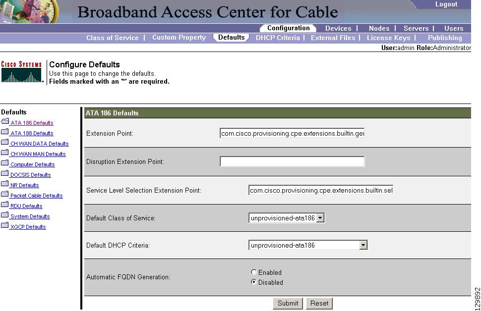
Table 11-2 identifies the fields and buttons shown in Figure 11-2. In many cases, the parameters that appear on this page also appear in other default pages.
|
|
|
|---|---|
Extension Point |
Identifies the extension point to execute when generating a configuration for a device of this technology. |
Disruption Extension Point |
Identifies the extension point to be executed to disrupt a device of this technology. |
Service Level Selection Extension Point |
Identifies the extension used to determine the DHCP criteria and Class of Service required for a device. |
Default Class of Service |
Identifies the current default Class of Service for a specific device technology, in this example, ATA186. New, unrecognized devices of that technology type will be assigned to this Class of Service. Use the drop-down list to select a new default value. |
Default DHCP Criteria |
Identifies the current default DHCP criteria for a specific device technology, in this example, ATA186. New, unrecognized devices of that technology type will have this default DHCP criteria assigned. Use the drop-down list to select a new default value. |
Automatic FQDN Generation |
Automatically generates a host and domain name for the device. Two selectable options are available: • • Note |
Submit |
Activates the changes you have made. After the administrative database has been updated the Configure Defaults page will reflect the changes you have made. |
Reset |
Returns all settings to their previous setting. |
ATA 188 Defaults
The Cisco ATA 188 interfaces regular telephones with IP-based ethernet telephony networks. The ATA 188 provides true, next-generation VoIP terminations to support the needs of the enterprise, small-office environments, and emerging VoIP managed voice services and local services market.
The Configure ATA 188 Defaults page displays a list of default values currently available to support the ATA 188. The default parameters displayed for the ATA 188 are identical to those displayed for the ATA 186, although the values you select could be different.
CableHome WAN Defaults
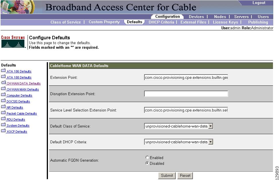
There are two distinct CableHome WAN default screens: one for WAN-Data devices and one for WAN-MAN devices. In either case, select the desired defaults from the list on the left pane. Each WAN default page contains identical fields and buttons as described in Table 11-3.
|
|
|
|---|---|
Extension Point |
Identifies the extension point to execute when generating a configuration for a WAN device. |
Disruption Extension Point |
Identifies the extension point to be executed to disrupt a WAN device. |
Service Level Selection Extension Point |
Identifies the extension used to determine the DHCP criteria and Class of Service required for a device. |
Default Class of Service |
Identifies the current default Class of Service for a WAN-Data. New, unrecognized WAN devices are assigned to this Class of Service. Use the drop-down list to select a new default value. |
Default DHCP Criteria |
Identifies the current default DHCP criteria for a specific device technology. New, unrecognized WAN devices are assigned this default DHCP criteria. Use the drop-down list to select a new default value. |
Automatic FQDN Generation |
Automatically generates a host and domain name for the device. Two selectable options are available: • • Note |
Submit |
Activates the changes you have made. After the administrative database has been updated the Configure Defaults page will reflect the changes you have made. |
Reset |
Returns all settings to their previous setting. |
CableHome WAN-Data Defaults
When you select the CH WAN-Data Defaults link, the CableHome WAN-Data Defaults page appears. See Figure 11-3. Use this page to configure the WAN-Data device.
Figure 11-3 Configure Defaults-CableHome WAN-Data Defaults Page
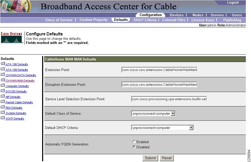
CableHome WAN-MAN Defaults
When you select the CH WAN-MAN Defaults link, the CableHome WAN-MAN Defaults page appears. See Figure 11-4. Use this page to configure the WAN-MAN device type.
Figure 11-4 Configure Defaults-CableHome WAN-MAN Defaults Page
Computer Defaults
The Computer Defaults page displays a list of default values currently applied to the computers supported by BAC. See Figure 11-5.
Figure 11-5 Configure Defaults-Computer Defaults Page
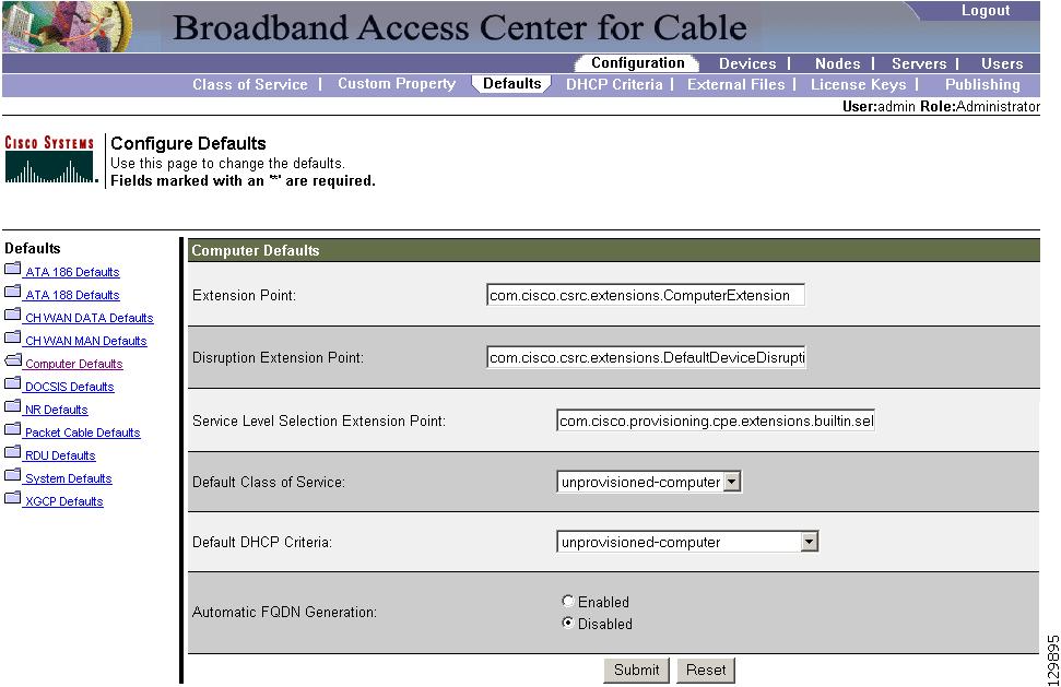
Refer to Table 11-2 for the description of all fields and buttons appearing in Figure 11-5.
Note ![]() Changes to the default Class of Service or default DHCP criteria cause regeneration to occur. Other changes made to this page do not affect existing devices.
Changes to the default Class of Service or default DHCP criteria cause regeneration to occur. Other changes made to this page do not affect existing devices.
DOCSIS Defaults
When the DOCSIS Defaults option is selected, the DOCSIS Defaults page appears. See Figure 11-6.
Use this page to display a list of default DOCSIS values currently applied to cable modems that
BAC supports.
Figure 11-6 Configure Defaults-DOCSIS Defaults Page

Note ![]() Changes to the default Class of Service or default DHCP criteria cause regeneration to occur. Changes to any TFTP option come into effect starting from the next TFTP transfer.
Changes to the default Class of Service or default DHCP criteria cause regeneration to occur. Changes to any TFTP option come into effect starting from the next TFTP transfer.
Refer to Table 11-4 for the description of all fields and buttons appearing in Figure 11-6.
|
|
|
|---|---|
Extension Point |
Identifies the extension point to execute when generating a configuration for a DOCSIS device. |
Disruption Extension Point |
Identifies the extension point to be executed to disrupt a DOCSIS device. |
Service Level Selection Extension Point |
Identifies the extension used to determine the DHCP criteria and Class of Service required for a device. |
Default Class of Service |
Identifies the current default Class of Service for a device. New, unrecognized devices are assigned to this Class of Service. Use the drop-down list to select a new default value. |
Default DHCP Criteria |
Identifies the current default DHCP criteria for a specific device technology. New, unrecognized devices are assigned this default DHCP criteria. Use the drop-down list to select a new default value. |
TFTP Modem Address Option |
Identifies whether the TFTP modem address option is enabled. |
TFTP Time Stamp Option |
Identifies whether the TFTP server will issue a timestamp. |
Automatic FQDN Generation |
Automatically generates a host and domain name for the device. Two selectable options are available: • • Note |
CMTS Shared Secret |
Identifies the character string that BAC uses in the calculation of the CMTS MIC in the configuration file. The CMTS uses it to authenticate the configuration file that a cable modem submits to the CMTS for authorization. |
CMTS Default Docsis Version |
Specifies the default DOCSIS version used by all CMTSs. If you do not enter a DOCSIS version in this field, it will default to version 1.0. |
Relay Agent IP Address to CMTS Version Mapping file |
Identifies the mapping file used by the CMTS. This file specifies the DOCSIS version that the CMTS will use. |
Submit |
Activates the changes you have made. After the administrative database has been updated the Configure Defaults page will reflect the changes you have made. |
Reset |
Returns all settings to their previous setting. |
Note ![]() If you enable either or both of the TFTP options on this page, that appropriate TFTP information is included in the TFTP file before it is sent to the DOCSIS cable modem.
If you enable either or both of the TFTP options on this page, that appropriate TFTP information is included in the TFTP file before it is sent to the DOCSIS cable modem.
Network Registrar Defaults
BAC provides Network Registrar (NR) extension points that allow BAC to pull information from incoming DHCP packets to detect a device's technology. The extension points also let BAC respond to device DHCP requests with options that correspond to the configuration stored at the DPE.
When the NR Defaults option is selected, the NR Defaults page appears. See Figure 11-7.
Figure 11-7 Configure Defaults-NR Defaults Page
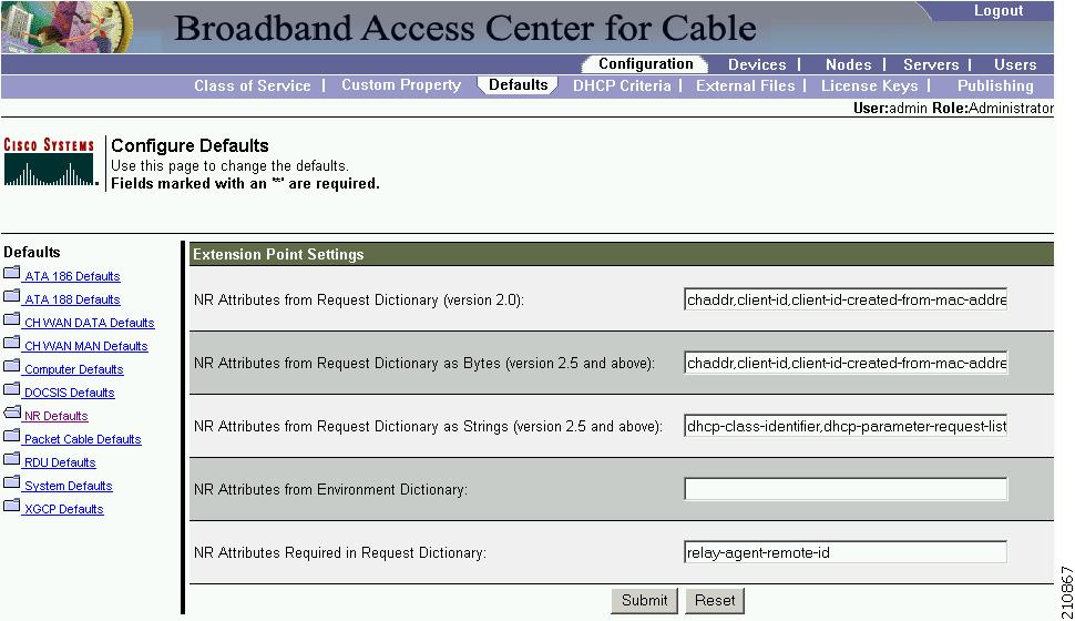
Refer to Table 11-5 for the description of all fields and buttons appearing in Figure 11-7.
Note ![]() Changes made to this page do not take effect until the Network Registrar extensions are reloaded.
Changes made to this page do not take effect until the Network Registrar extensions are reloaded.
PacketCable Defaults
The PacketCable Defaults page identifies those defaults necessary to support the PacketCable voice technology. When selected the PacketCable Defaults page appears. See Figure 11-8.
Figure 11-8 Configure Defaults-PacketCable Defaults Page

Table 11-6 identifies the fields and buttons that are unique to this defaults page.
RDU Defaults
When you select the RDU defaults link, the RDU Defaults page appears. See Figure 11-9. Use this page to configure the RDU to communicate with Network Registrar. For additional information, refer to the Cisco Network Registrar User's Guide, 6.2.1.
Figure 11-9 Configure Defaults-RDU Defaults Page
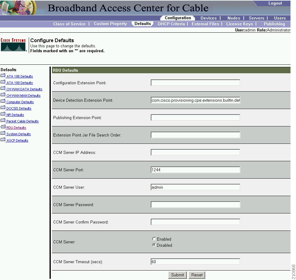
Table 11-7 describes all fields and buttons appearing in Figure 11-9.
Note ![]() See Managing RDU Extensions, for information on RDU extension points.
See Managing RDU Extensions, for information on RDU extension points.
System Defaults
When you select the Systems Defaults link, the System Defaults page appears. See Figure 11-10.
Figure 11-10 Configure Defaults-System Defaults Page
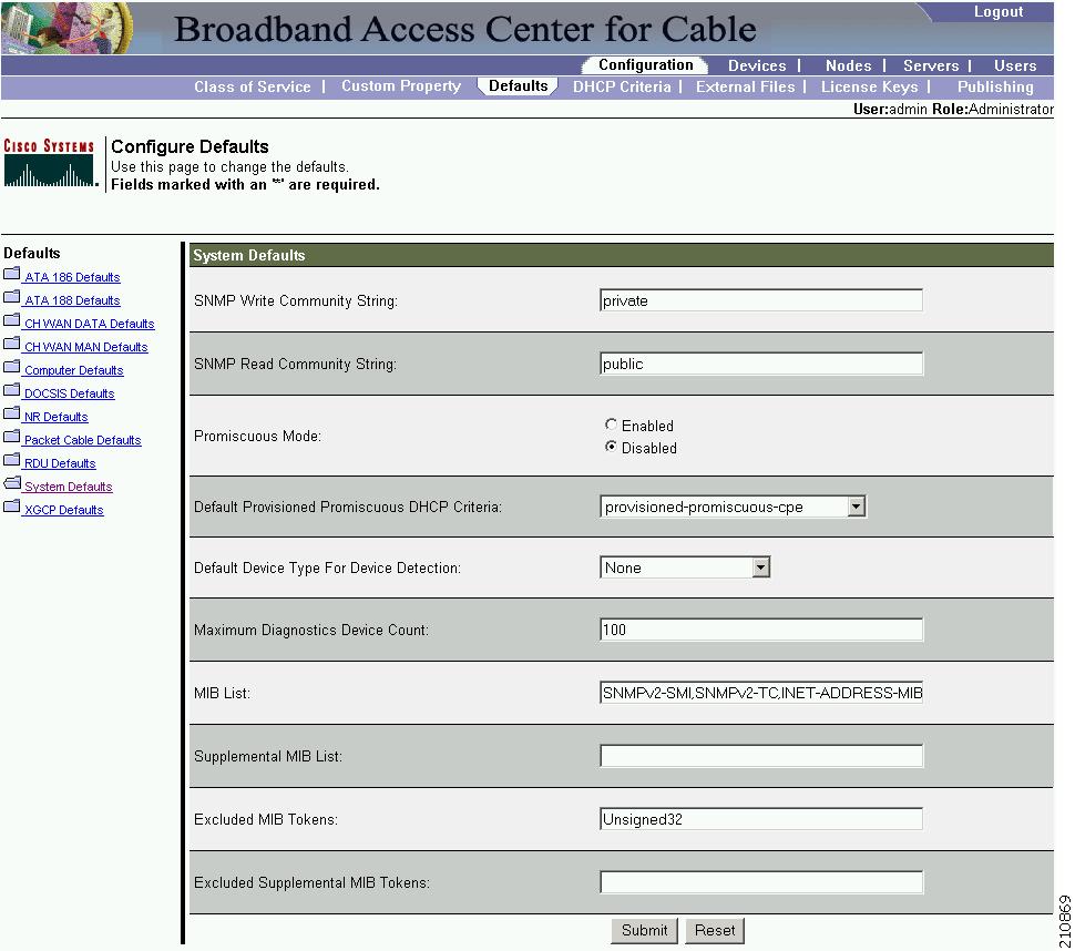
Note ![]() You can configure the default values by using the BAC API.
You can configure the default values by using the BAC API.
Table 11-8 describes all fields and buttons appearing in Figure 11-10.
Gateway (xGCP) Control Protocol Defaults
XGCP is a Gateway Control Protocol that lets external call agents control gateways in a VoIP environment. The xGCP Defaults page (Figure 11-11) displays a list of default values currently applied to the xGCP gateway devices supported by BAC.
Figure 11-11 Configure Defaults-XGCP Defaults Page
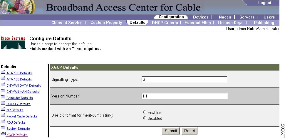
Table 11-9 describes all fields and buttons appearing in Figure 11-11.
Note ![]() Subsequent device configurations will include the changes you implement here. However, all existing configurations are not changed. To make the changes in any existing configuration, you must regenerate the configuration using the API.
Subsequent device configurations will include the changes you implement here. However, all existing configurations are not changed. To make the changes in any existing configuration, you must regenerate the configuration using the API.
Configuring DHCP Criteria
In BAC, DHCP criteria describe the specific criteria for a device when selecting a scope in Network Registrar. For example, a DHCP criteria called provisioned-docsis has an inclusion selection tag called tagProvisioned. The DHCP criteria is associated with a DOCSIS modem. When this modem requests an IP address from the Network Registrar, Network Registrar looks for scopes associated with the scope-selection tag tagProvisioned.
To access the DHCP Criteria page:
Step 1 ![]() Choose Configuration on the Primary Navigation bar.
Choose Configuration on the Primary Navigation bar.
Step 2 ![]() Choose DHCP Criteria from the Secondary Navigation bar and the Manage DHCP Criteria page appears.
Choose DHCP Criteria from the Secondary Navigation bar and the Manage DHCP Criteria page appears.
Adding DHCP Criteria
To add a DHCP criteria:
Step 1 ![]() Click Add, on the DHCP Criteria page, and the Add DHCP Criteria page appears.
Click Add, on the DHCP Criteria page, and the Add DHCP Criteria page appears.
Step 2 ![]() Enter the name of the DHCP criteria you want to create.
Enter the name of the DHCP criteria you want to create.
Step 3 ![]() Enter the DHCP Criteria client-class name.
Enter the DHCP Criteria client-class name.
Step 4 ![]() Enter the inclusion and exclusion selection tags.
Enter the inclusion and exclusion selection tags.
Note ![]() When creating new DHCP criteria, the client-class and Inclusion and Exclusion selection tag names you enter must be the exact names from within Network Registrar. For additional information on client class and selection tags, refer to the Cisco Network Registrar User's Guide, 6.2.1, and the Cisco Network Registrar CLI Reference, 6.2.1. You should specify either the client class, or inclusion and exclusion selection tag names, when creating a new DHCP criteria.
When creating new DHCP criteria, the client-class and Inclusion and Exclusion selection tag names you enter must be the exact names from within Network Registrar. For additional information on client class and selection tags, refer to the Cisco Network Registrar User's Guide, 6.2.1, and the Cisco Network Registrar CLI Reference, 6.2.1. You should specify either the client class, or inclusion and exclusion selection tag names, when creating a new DHCP criteria.
Step 5 ![]() You can add or modify the properties that are added on the DHCP criteria. Enter or select a Property Name, or select an existing name, and enter or modify the appropriate Property Value.
You can add or modify the properties that are added on the DHCP criteria. Enter or select a Property Name, or select an existing name, and enter or modify the appropriate Property Value.
Step 6 ![]() Click Add after changing or creating the property name-property value pair.
Click Add after changing or creating the property name-property value pair.
Step 7 ![]() Click Submit. After the DHCP criteria is successfully added in the RDU database, it will be visible in the Manage DHCP Criteria Page.
Click Submit. After the DHCP criteria is successfully added in the RDU database, it will be visible in the Manage DHCP Criteria Page.
Modifying DHCP Criteria
To modify existing DHCP criteria:
Step 1 ![]() On the Manage DHCP criteria page, click the DHCP criteria link that you want to modify and the Modify DHCP Criteria page appears.
On the Manage DHCP criteria page, click the DHCP criteria link that you want to modify and the Modify DHCP Criteria page appears.
Step 2 ![]() Make the desired changes to the client class, inclusion and exclusion selection tags, and the property value settings.
Make the desired changes to the client class, inclusion and exclusion selection tags, and the property value settings.
Step 3 ![]() Click Submit. After successful modification of the DHCP criteria in the RDU Database, the Manage DHCP Criteria page appears.
Click Submit. After successful modification of the DHCP criteria in the RDU Database, the Manage DHCP Criteria page appears.
Note ![]() Subsequent device configurations will include the changes you implement here. All existing configurations are regenerated, although the devices on the network will not get the new configuration until they are rebooted.
Subsequent device configurations will include the changes you implement here. All existing configurations are regenerated, although the devices on the network will not get the new configuration until they are rebooted.
Deleting DHCP Criteria
Deleting DHCP criteria using the administrator application does not delete the actual DHCP server configurations from the DHCP server. You must delete the DHCP server configurations manually. To delete an existing criteria:
Step 1 ![]() Choose Configuration on the Primary Navigation bar.
Choose Configuration on the Primary Navigation bar.
Step 2 ![]() Choose DHCP Criteria from the Secondary Navigation bar and the Manage DHCP Criteria page appears.
Choose DHCP Criteria from the Secondary Navigation bar and the Manage DHCP Criteria page appears.
Step 3 ![]() Click the Delete icon corresponding to the criteria you want to delete, and a deletion dialog box appears.
Click the Delete icon corresponding to the criteria you want to delete, and a deletion dialog box appears.
Step 4 ![]() Click OK to delete the criteria or click Cancel to abort the operation. The Manage DHCP Criteria page appears.
Click OK to delete the criteria or click Cancel to abort the operation. The Manage DHCP Criteria page appears.
Note ![]() You can delete a DHCP criteria only if there are no devices associated with that criteria, and it is not designated as the default DHCP criteria. If a DHCP criteria has devices associated with it, you must associate a different DHCP criteria before deleting the criteria.
You can delete a DHCP criteria only if there are no devices associated with that criteria, and it is not designated as the default DHCP criteria. If a DHCP criteria has devices associated with it, you must associate a different DHCP criteria before deleting the criteria.
Managing External Files
By using the BAC administrator user interface, you can manage the TFTP server files or template files for dynamic generation for DOCSIS, PacketCable MTAs, and WAN-MAN files, or software images for devices. See Figure 11-12. Use this page to add, delete, replace, or export any file type, including:
•![]() Template files—These are text files that contain DOCSIS, PacketCable, or CableHome options and values that, when used in conjunction with a particular Class of Service, provide dynamic file generation.
Template files—These are text files that contain DOCSIS, PacketCable, or CableHome options and values that, when used in conjunction with a particular Class of Service, provide dynamic file generation.
Note ![]() Template files can be created in any text editor, but must have a .tmpl file type. For additional template information, refer to Developing Template Files, page 8-1.
Template files can be created in any text editor, but must have a .tmpl file type. For additional template information, refer to Developing Template Files, page 8-1.
•![]() Static configuration files—These files are used as a configuration file for a device. For example, a static configuration file, called gold.cm, would identify the gold DOCSIS Class of Service. BAC treats this file type like any other binary file.
Static configuration files—These files are used as a configuration file for a device. For example, a static configuration file, called gold.cm, would identify the gold DOCSIS Class of Service. BAC treats this file type like any other binary file.
•![]() IOS images—These are images stored in firmware for a Cisco device. The Cisco device can upload the image to upgrade its functionality. BAC treats this file type like any other binary file.
IOS images—These are images stored in firmware for a Cisco device. The Cisco device can upload the image to upgrade its functionality. BAC treats this file type like any other binary file.
Note ![]() Once you click the Search button on the View External Files page, Figure 11-12 appears.
Once you click the Search button on the View External Files page, Figure 11-12 appears.
Figure 11-12 View External Files Page
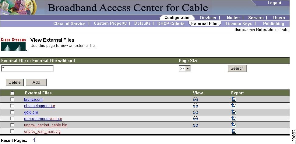
Table 11-10 identifies the fields and buttons shown in Figure 11-12.
Adding External Files
To add an existing external file:
Step 1 ![]() Choose Configuration on the Primary Navigation bar.
Choose Configuration on the Primary Navigation bar.
Step 2 ![]() Choose External Files from the Secondary Navigation bar. The View External Files page appears.
Choose External Files from the Secondary Navigation bar. The View External Files page appears.
Step 3 ![]() Click Add and the Add External Files page appears.
Click Add and the Add External Files page appears.
Step 4 ![]() Enter the Source filename and the External filename.
Enter the Source filename and the External filename.
Note ![]() If you do not know the exact name of the source file, use the Browse function to navigate to the desired directory and select the file. File sizes up to 4 MB are supported.
If you do not know the exact name of the source file, use the Browse function to navigate to the desired directory and select the file. File sizes up to 4 MB are supported.
Step 5 ![]() Click Submit. The View External Files page appears to indicate that the file has been added.
Click Submit. The View External Files page appears to indicate that the file has been added.
Viewing External Files
To view the contents of a DOCSIS or PacketCable voice technology external file:
Step 1 ![]() Choose Configuration on the Primary Navigation bar.
Choose Configuration on the Primary Navigation bar.
Step 2 ![]() Choose External Files from the Secondary Navigation bar. The View External Files page appears.
Choose External Files from the Secondary Navigation bar. The View External Files page appears.
Step 3 ![]() Search for the required file using the search field and appropriate wildcard characters.
Search for the required file using the search field and appropriate wildcard characters.
Step 4 ![]() Click the View Details icon (
Click the View Details icon ( ) corresponding to the DOCSIS, CableHome WAN-MAN, and PacketCable MTA binary configuration files. A View Binary File Contents page appears. Figure 11-13 identifies sample binary file content.
Figure 11-13 Sample Binary File Content
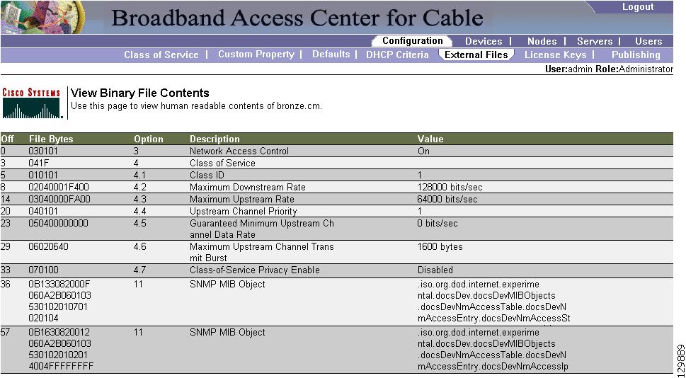
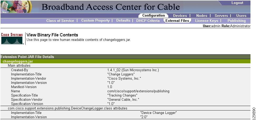
Figure 11-14 identifies sample Jar file content.
Figure 11-14 Sample Jar File Content
Replacing External Files
To replace an existing external file:
Step 1 ![]() Choose Configuration on the Primary Navigation bar.
Choose Configuration on the Primary Navigation bar.
Step 2 ![]() Choose External Files from the Secondary Navigation bar.
Choose External Files from the Secondary Navigation bar.
Step 3 ![]() Select the link that corresponds to the file you want to replace from the search output list. The Replace External Files page appears. Note that the selected filename already appears on this page.
Select the link that corresponds to the file you want to replace from the search output list. The Replace External Files page appears. Note that the selected filename already appears on this page.
Step 4 ![]() Enter the path and filename of the source file to be used as a replacement for the displayed external filename.
Enter the path and filename of the source file to be used as a replacement for the displayed external filename.
Note ![]() If you do not know the exact name or location of the source file, use the Browse button to navigate to the desired directory and select the file.
If you do not know the exact name or location of the source file, use the Browse button to navigate to the desired directory and select the file.
Step 5 ![]() Click Submit. After submitting the replacement file, a confirmation page appears to indicate that, after replacement, BAC will regenerate configurations for the affected devices.
Click Submit. After submitting the replacement file, a confirmation page appears to indicate that, after replacement, BAC will regenerate configurations for the affected devices.
Step 6 ![]() Click OK and the View External Files page appears.
Click OK and the View External Files page appears.
Note ![]() All devices using this file through a Class of Service are regenerated after the replacement is finished.
All devices using this file through a Class of Service are regenerated after the replacement is finished.
Exporting External Files
You can copy external files to your local hard drive using the export function.
Note ![]() The procedure described below assumes that you are using Internet Explorer. This procedure is different if you are using Netscape Navigator.
The procedure described below assumes that you are using Internet Explorer. This procedure is different if you are using Netscape Navigator.
To export a file:
Step 1 ![]() Choose Configuration on the Primary Navigation bar.
Choose Configuration on the Primary Navigation bar.
Step 2 ![]() Choose External Files from the Secondary Navigation bar.
Choose External Files from the Secondary Navigation bar.
Step 3 ![]() Identify the external file that you want to export.
Identify the external file that you want to export.
Step 4 ![]() Click the Export icon (
Click the Export icon ( ) and you are prompted to either open the file or save it.
Step 5 ![]() Return to the BAC user interface.
Return to the BAC user interface.
Deleting External Files
Complete this procedure to delete an existing external file:
Step 1 ![]() Choose Configuration on the Primary Navigation bar.
Choose Configuration on the Primary Navigation bar.
Step 2 ![]() Choose External Files from the Secondary Navigation bar.
Choose External Files from the Secondary Navigation bar.
Step 3 ![]() In the External Files field, enter the filename of the external file that you want to modify.
In the External Files field, enter the filename of the external file that you want to modify.
Step 4 ![]() Click Search. The appropriate file will appear in the External Files list.
Click Search. The appropriate file will appear in the External Files list.
Step 5 ![]() Choose the appropriate file or files.
Choose the appropriate file or files.
Step 6 ![]() Click Delete.
Click Delete.
Note ![]() You cannot delete a file that has a Class of Service associated with it. You must remove the Class of Service association before proceeding. See Configuring Class of Service, for additional information.
You cannot delete a file that has a Class of Service associated with it. You must remove the Class of Service association before proceeding. See Configuring Class of Service, for additional information.
Managing License Keys
Software licenses are used to activate specific features or to increase the functionality of your installation. Each license is available as either a permanent license or an evaluation license.
•![]() Permanent—A permanent license is purchased for use in your network environment and activates the specific features for which it is intended.
Permanent—A permanent license is purchased for use in your network environment and activates the specific features for which it is intended.
•![]() Evaluation—An evaluation license enables functionality for a specific amount of time after installation. You can upgrade an evaluation license to a permanent license by entering a new permanent license number.
Evaluation—An evaluation license enables functionality for a specific amount of time after installation. You can upgrade an evaluation license to a permanent license by entering a new permanent license number.
When you upgrade from an evaluation license to a permanent license, you do not have to reinstall the software or reconfigure BAC. You simply have to provide the permanent license via the BAC administrator user interface.
The Manage License Keys page displays a list of licenses that have been entered for your implementation. This BAC release supports both evaluation and permanent licenses for high-speed data (DOCSIS cable modems), PacketCable MTAs, ATAs, DPEs, CableHome WAN-MAN and WAN-Data devices, and computers. The status of each available license appears as active or expired (shown by the expiration date).
Note ![]() You can upgrade a permanent license to increase the number of authorized devices by adding an additional license. When you reach the limit of your number of licensed devices you cannot provision new devices, but existing devices that are already provisioned continue to receive service.
You can upgrade a permanent license to increase the number of authorized devices by adding an additional license. When you reach the limit of your number of licensed devices you cannot provision new devices, but existing devices that are already provisioned continue to receive service.
Figure 11-15 identifies a sample Manage License Keys page.
Figure 11-15 Manage License Keys Page

Adding and Modifying a License
To add, modify, or upgrade a license:
Step 1 ![]() Choose Configuration > License Keys.
Choose Configuration > License Keys.
Step 2 ![]() Obtain your new license key from either your Cisco representative or the Cisco Technical Assistance Center (TAC) website. See the Preface in this guide for TAC contact information.
Obtain your new license key from either your Cisco representative or the Cisco Technical Assistance Center (TAC) website. See the Preface in this guide for TAC contact information.
Step 3 ![]() Enter the new license key in the License Key field.
Enter the new license key in the License Key field.
Step 4 ![]() Click Add/Upgrade to install the new license key. If you enter a permanent license key, it overwrites the corresponding evaluation key (if that key was installed). If you enter a license key (permanent or evaluation) for a new technology, it will appear in the technology list.
Click Add/Upgrade to install the new license key. If you enter a permanent license key, it overwrites the corresponding evaluation key (if that key was installed). If you enter a license key (permanent or evaluation) for a new technology, it will appear in the technology list.
Deleting a License
To delete a license:
Step 1 ![]() Choose Configuration > License Keys from the Navigation bar.
Choose Configuration > License Keys from the Navigation bar.
The Manage License Keys page appears.
Step 2 ![]() Copy the license key corresponding to the technology you want to delete.
Copy the license key corresponding to the technology you want to delete.
Step 3 ![]() Paste the license key in the License Key field. Click Delete.
Paste the license key in the License Key field. Click Delete.
A Confirmation dialog box appears.
Step 4 ![]() To confirm deleting the license key, click Yes; otherwise click No.
To confirm deleting the license key, click Yes; otherwise click No.
The license key disappears from the Manage License Keys page.
Note ![]() To confirm if the license has been deleted, verify if the action has been recorded in audit.log.
To confirm if the license has been deleted, verify if the action has been recorded in audit.log.
Managing RDU Extensions
Creating a custom extension point is a programming activity that can, when used with the BAC administrator user interface, allows you to augment BAC behavior or add support for new device technologies.
Before familiarizing yourself with managing extensions, you should know the RDU extension points that BAC requires. At least one disruption extension must be attached to the associated technology's disruption extension point when disrupting devices on behalf of a batch.
Table 11-11 lists the RDU extension points that BAC requires to execute extensions.
Managing extensions includes:
•![]() Installing RDU Custom Extension Points
Installing RDU Custom Extension Points
Note ![]() You can specify multiple extension points by specifying the extension points in a comma-separated list.
You can specify multiple extension points by specifying the extension points in a comma-separated list.
Writing a New Class
This procedure is included to better illustrate the entire custom extension creation process. You can create many different types of extensions; for the purposes of this procedure, a new Publishing Extension Point is used.
To write the new class:
Step 1 ![]() Create a Java source file for the custom publishing extension, and compile it.
Create a Java source file for the custom publishing extension, and compile it.
Step 2 ![]() Create a manifest file for the Jar file that will contain the extension class.
Create a manifest file for the Jar file that will contain the extension class.
Note ![]() For detailed information on creating a manifest file and using the command-line JAR tool, refer to Java documentation.
For detailed information on creating a manifest file and using the command-line JAR tool, refer to Java documentation.
For example:
Name: com/cisco/support/extensions/configgeneration
Specification-Title: "DOCSIS TOD synchronization"
Specification-Version: "1.0"
Specification-Vendor: "General Cable, Inc."
Implementation-Title: "Remove the time-servers DHCP option"
Implementation-Version: "1.0"
Implementation-Vendor: "Cisco Systems, Inc."
Note ![]() Java Jar file manifests contain attributes that are formatted as name-value pairs and support a group of attributes that provide package versioning information. While BAC accepts extension Jar files that do not contain this information, we recommend that you include a manifest with versioning information in the files to track custom RDU extensions.
Java Jar file manifests contain attributes that are formatted as name-value pairs and support a group of attributes that provide package versioning information. While BAC accepts extension Jar files that do not contain this information, we recommend that you include a manifest with versioning information in the files to track custom RDU extensions.
You can view manifest information from the administrator user interface (via Servers > RDU > View Regional Distribution Unit Details page. Detailed information on the installed extension Jar files and the loaded extension class files appears after the Device Statistics section. You can view manifest information from the RDU logs also.
Step 3 ![]() Create the Jar file for the custom extension point.
Create the Jar file for the custom extension point.
For example:
C:\>jar cm0vf manifest.txt removetimeservers.jar com
added manifest
adding: com/(in = 0) (out= 0)(stored 0%)
adding: com/cisco/(in = 0) (out= 0)(stored 0%)
adding: com/cisco/support/(in = 0) (out= 0)(stored 0%)
adding: com/cisco/support/extensions/(in = 0) (out= 0)(stored 0%)
adding: com/cisco/support/extensions/configgeneration/(in = 0) (out= 0)(stored 0%)
adding: com/cisco/support/extensions/configgeneration/
RemoveTimeServersExtension.class(in = 4038) (out= 4038)(stored 0%)
C:\>
Note ![]() You can give the Jar file any name. The name can be descriptive, but do not duplicate another existing Jar filename.
You can give the Jar file any name. The name can be descriptive, but do not duplicate another existing Jar filename.
Installing RDU Custom Extension Points
After a Jar file is created, use the administrator user interface to install it:
Step 1 ![]() To add the new Jar file, see Adding External Files.
To add the new Jar file, see Adding External Files.
Note ![]() Select the JAR file type. Use the Browse function to locate the Jar file created in the procedure described in Writing a New Class, and select this file as the Source File. Leaving the External File Name blank assigns the same filename for both source and external files. The external filename is what you will see on the administrator user interface.
Select the JAR file type. Use the Browse function to locate the Jar file created in the procedure described in Writing a New Class, and select this file as the Source File. Leaving the External File Name blank assigns the same filename for both source and external files. The external filename is what you will see on the administrator user interface.
Step 2 ![]() Click Submit.
Click Submit.
Step 3 ![]() Return to the RDU Defaults page and note if the newly added Jar file appears in the Extension Point Jar File Search Order field.
Return to the RDU Defaults page and note if the newly added Jar file appears in the Extension Point Jar File Search Order field.
Step 4 ![]() Enter the extension class name in the Publishing Extension Point field.
Enter the extension class name in the Publishing Extension Point field.
Note ![]() The RDU returns an error if the class name does not exist within the Jar file. This error occurs mostly when replacing a Jar file, if, for example, the class you set up is not found in the replacement Jar file.
The RDU returns an error if the class name does not exist within the Jar file. This error occurs mostly when replacing a Jar file, if, for example, the class you set up is not found in the replacement Jar file.
Step 5 ![]() Click Submit to commit the changes to the RDU database.
Click Submit to commit the changes to the RDU database.
Step 6 ![]() View the RDU extensions to ensure that the correct extensions are loaded.
View the RDU extensions to ensure that the correct extensions are loaded.
Viewing RDU Extensions
You can view the attributes of all RDU extensions directly from the View Regional Distribution Unit Details page. This page displays details on the installed extension Jar files and the loaded extension class files. See Viewing Regional Distribution Unit Details, page 10-25.
Publishing Provisioning Data
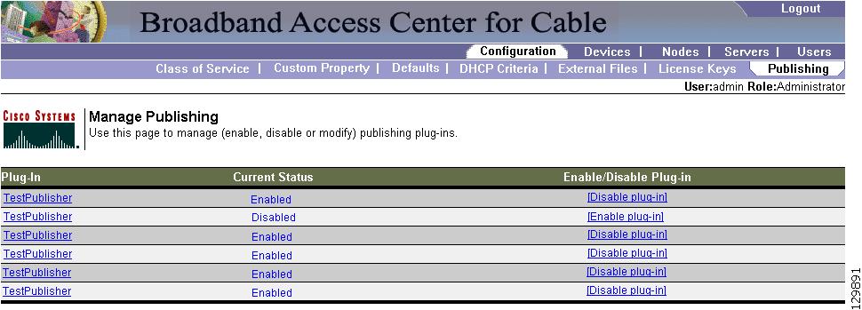
BAC has the capability to publish the provisioning data it tracks to an external datastore in real time. To do this, a publishing plug-in must be developed to write the data to the desired datastore. The Manage Publishing page, shown in Figure 11-16, identifies information such as the plug-in name, its current status (whether it is enabled or disabled), and switch to enable or disable it.
You can enable as many plug-ins as required by your implementation, but remember that the use of publishing plug-ins can decrease system performance.
Note ![]() BAC does not ship with any publishing plug-ins. You must create your own plug-ins and load them into BAC in the same way as Jar files are (see Adding External Files). Then, manage the plug-ins from the Manage Publishing page. The plug-ins shown in Figure 11-16 are for illustration only.
BAC does not ship with any publishing plug-ins. You must create your own plug-ins and load them into BAC in the same way as Jar files are (see Adding External Files). Then, manage the plug-ins from the Manage Publishing page. The plug-ins shown in Figure 11-16 are for illustration only.
Figure 11-16 Manage Publishing Page
Publishing Datastore Changes
To enable or disable a publishing plug-in:
Step 1 ![]() Choose Configuration on the Primary Navigation bar.
Choose Configuration on the Primary Navigation bar.
Step 2 ![]() Choose Publishing on the Secondary Navigation bar.
Choose Publishing on the Secondary Navigation bar.
The Manage Publishing page appears. This page displays a list of all available database plug-ins and identifies the current status of each.
Step 3 ![]() Click on the appropriate status indicator to enable or disable the required plug-in. Note that as you click the status, it toggles between the two states. See Figure 11-16.
Click on the appropriate status indicator to enable or disable the required plug-in. Note that as you click the status, it toggles between the two states. See Figure 11-16.
Modifying Publishing Plug-In Settings
These settings are a convenient way for plug-in writers to store plug-in settings in the RDU for their respective datastore. To modify the publishing plug-in settings:
Step 1 ![]() Choose Configuration on the Primary Navigation bar.
Choose Configuration on the Primary Navigation bar.
Step 2 ![]() Choose Publishing on the Secondary Navigation bar, and the Manage Publishing page appears.
Choose Publishing on the Secondary Navigation bar, and the Manage Publishing page appears.
Step 3 ![]() Click the link corresponding to the plug-in you want to modify. The Modify Publishing Plug-Ins page appears.
Click the link corresponding to the plug-in you want to modify. The Modify Publishing Plug-Ins page appears.
Table 11-12 identifies the fields shown in the Modify Publishing Plug-Ins page.
Step 4 ![]() Enter the required values in the Server, Port, IP Address, User, Password, and Confirm Password fields. These are all required fields and you must supply this information before proceeding.
Enter the required values in the Server, Port, IP Address, User, Password, and Confirm Password fields. These are all required fields and you must supply this information before proceeding.
Step 5 ![]() Click Submit to make the changes to the selected plug-in, or click Reset to clear all fields on this page.
Click Submit to make the changes to the selected plug-in, or click Reset to clear all fields on this page.
Configuring SRV Records in the Network Registrar DNS Server
You must configure the Network Registrar DNS server to operate with the KDC. To set up this configuration, refer to your Network Registrar documentation and these instructions.
Note ![]() It is recommended that you create a zone name that matches the desired realm name, and that the only DNS record in this special zone (other than the records required by the DNS server to maintain the zone) should be the SRV record for the realm. This example assumes that the desired Kerberos realm is voice.acme.com, and that all other KDC, Network Registrar, and DPE configuration has been performed. The FQDN of the KDC is assumed to be kdc.acme.com.
It is recommended that you create a zone name that matches the desired realm name, and that the only DNS record in this special zone (other than the records required by the DNS server to maintain the zone) should be the SRV record for the realm. This example assumes that the desired Kerberos realm is voice.acme.com, and that all other KDC, Network Registrar, and DPE configuration has been performed. The FQDN of the KDC is assumed to be kdc.acme.com.
Step 1 ![]() Start the nrcmd CLI (which resides, by default, in the /opt/nwreg2/local/usrbin directory), and enter your username and password.
Start the nrcmd CLI (which resides, by default, in the /opt/nwreg2/local/usrbin directory), and enter your username and password.
Step 2 ![]() Enter this command to create a zone for the Kerberos realm:
Enter this command to create a zone for the Kerberos realm:
nrcmd> zone voice.acme.com create primary <address of nameserver> hostmaster
Step 3 ![]() Enter this command to add the SRV record to the new zone:
Enter this command to add the SRV record to the new zone:
nrcmd> zone voice.acme.com. addRR _kerberos._udp. srv 0 0 88 <address of KDC>
Step 4 ![]() Enter these commands to save and reload the DNS server:
Enter these commands to save and reload the DNS server:
nrcmd> save
nrcmd> dns reload
Configuring SNMPv3 Cloning on the RDU and DPE for
Secure Communication with PacketCable MTAs
BAC lets you enable an external network manager for SNMPv3 access to MTA devices. Additionally, the RDU is capable of performing SNMPV3 operations in a specific MTA.
To enable this capability, set the security key material at the DPEs and RDU. After the key material has been set, the BAC API calls that are used to create cloned SNMPv3 entries are enabled.
Note ![]() Enabling this capability impacts provisioning performance.
Enabling this capability impacts provisioning performance.
Creating the Key Material and Generating the Key
Creating the key material is a two-step process:
1. ![]() Run a script command on the RDU.
Run a script command on the RDU.
2. ![]() Run a CLI command on the DPE.
Run a CLI command on the DPE.
Note ![]() This shared secret is not the same shared secret as the CMTS or the BAC shared secrets.
This shared secret is not the same shared secret as the CMTS or the BAC shared secrets.
To create the key material:
Step 1 ![]() From the BPR_HOME/rdu/bin directory, run this script on the RDU:
From the BPR_HOME/rdu/bin directory, run this script on the RDU:
# generateSharedSecret.sh password
where password is any password, from 6 to 20 characters, that you create. This password is then used to generate a 46-byte key. This key is stored in a file, called keymaterial.txt, that resides in the BPR_HOME/rdu/conf directory.
Step 2 ![]() Run the packetcable snmp key-material DPE CLI command, with the password used in Step 1 to generate that key, on all DPEs for which this voice technology is enabled. This command generates the same 46-byte key on the DPE and ensures that the RDU and DPEs are synchronized and can communicate with the MTA securely.
Run the packetcable snmp key-material DPE CLI command, with the password used in Step 1 to generate that key, on all DPEs for which this voice technology is enabled. This command generates the same 46-byte key on the DPE and ensures that the RDU and DPEs are synchronized and can communicate with the MTA securely.
Automatic FQDN Generation
When configuring the PacketCable voice technology, a fully qualified domain name (FQDN) must reside in the BAC database for each voice device, because the KDC queries the registration server for that FQDN. The BAC automatic FQDN generation feature is not limited to use by any single voice technology; it can be used by any BAC technology.
Automatically Generated FQDN Format
An automatically generated FQDN in BAC follows this format:
prefixhtype-hlen-aa-bb-cc-dd-ee-ffsuffix.domain
•![]() prefix, suffix, and domain—Identify the information that you set from the BAC administrator user interface or the provisioning API.
prefix, suffix, and domain—Identify the information that you set from the BAC administrator user interface or the provisioning API.
Note ![]() In the sample FQDN used here, prefix1,6,aa-bb-cc-dd-ee-ffsuffix is the generated hostname and domain is the domain name.
In the sample FQDN used here, prefix1,6,aa-bb-cc-dd-ee-ffsuffix is the generated hostname and domain is the domain name.
•![]() 1,6,aa-bb-cc-dd-ee-ff—Identifies the device MAC address.
1,6,aa-bb-cc-dd-ee-ff—Identifies the device MAC address.
The entry of a prefix and suffix property is optional. If you do not specify these properties, and a hostname is not specified during PacketCable MTA provisioning and, if neither the prefix nor suffix property is defined in the BAC property hierarchy, the device MAC address followed by the domain name are used as the generated FQDN.
For example:
A device with the MAC address 1,6,aa:bb:cc:dd:ee:ff will have this FQDN generated:
1-6-aa-bb-cc-dd-ee-ff.domain
When configuring for PacketCable and other technologies, the domain name property must also be configured. If you do not specify a domain name while provisioning a PacketCable MTA, the BAC property hierarchy is searched and, if it is not found, the MTA is not provisioned. If you do specify the domain name during MTA provisioning, that domain name is used regardless of the domain name property that is specified in the BAC property hierarchy.
Properties for Automatically Generated FQDNs
Properties can be defined at any acceptable point in the BAC property hierarchy. You can use the System Defaults, Technology Defaults, DHCP Criteria, or Class of Service to accomplish this, and you can also do this at the device level.
FQDN Validation
There are a few things to consider when entering the information that is used to generate an FQDN. These include:
•![]() Use only valid alphanumeric characters in the generated FQDN.
Use only valid alphanumeric characters in the generated FQDN.
•![]() Keep the length of each label (characters between the dots in the generated FQDN) to fewer than 63 characters.
Keep the length of each label (characters between the dots in the generated FQDN) to fewer than 63 characters.
•![]() Do not allow the overall length of the generated FQDN to exceed 254 characters.
Do not allow the overall length of the generated FQDN to exceed 254 characters.
Note ![]() The FQDN supports host and domain names as per RFC1035.
The FQDN supports host and domain names as per RFC1035.
Sample Automatic FQDN Generation
This section provides an example of creating an automatically generated FQDN.
Step 1 ![]() Choose the appropriate Class of Service, and set the
Choose the appropriate Class of Service, and set the /fqdn/domain property value to the DNS domain for all devices using this Class of Service. For the purposes of this example, assume that the domain in use is pctest.com, and that you want to provision a set of PacketCable devices into that domain.
Note ![]() If a domain is not specified, devices in the Class of Service will not receive a DHCP configuration from BAC.
If a domain is not specified, devices in the Class of Service will not receive a DHCP configuration from BAC.
Step 2 ![]() Click Submit.
Click Submit.
In this example, a device with MAC address 1,6,aa:bb:cc:dd:ee:ff will yield an automatically generated FQDN of 1-6-aa-bb-cc-dd-ee-ff.pctest.com. Additionally, the Automatic FQDN Generation field should be enabled in the device's default configuration.
 Feedback