Cisco CRS Carrier Routing System 8-Slot Line Card Chassis Enhanced Router Site Planning Guide
Bias-Free Language
The documentation set for this product strives to use bias-free language. For the purposes of this documentation set, bias-free is defined as language that does not imply discrimination based on age, disability, gender, racial identity, ethnic identity, sexual orientation, socioeconomic status, and intersectionality. Exceptions may be present in the documentation due to language that is hardcoded in the user interfaces of the product software, language used based on RFP documentation, or language that is used by a referenced third-party product. Learn more about how Cisco is using Inclusive Language.
- Updated:
- October 24, 2016
Chapter: Site Planning Considerations
Site Planning
Considerations
This chapter describes the general considerations to address while planning for the installation of the Cisco CRS Carrier Routing System 8-Slot Line Card Chassis Enhanced router. It does not repeat the specifications in Technical and Environmental Specifications, but you should keep those specifications in mind as you plan for your system.
This chapter includes the following sections:
- Basic Site and Installation Planning
- Tools Required for Installation
- Equipment Rack Considerations
- Aisle Spacing and Maintenance Access Floor Plan
- Power and Cooling Requirements
- System Console
- Cable Management
- Noise Control
- Cisco Installation Services
- System Testing, Certification, and Warranties
Basic Site and Installation Planning
As you plan for basic site and installation requirements, consider the following:
- Does the installation site have adequate power for the routing system?
- Can the routing system be positioned close to the AC or DC power source, and are the power receptacles easy to reach?
- Does the site have appropriate equipment racks with space available in which to install the system? Are additional equipment racks required? See the Equipment Rack Specifications section for information about rack requirements.
- Is there a scissor lift or similar lifting device available to lift the chassis into the equipment rack?
In addition, make sure that the installation site meets the following access requirements:
- At least 48 inches (122 cm) of clearance exists between rows of equipment racks. This space is needed to access components in the chassis. Additional clearance may be necessary for installation.
- Enough room exists for the system console terminal, and that the console cable is long enough to reach the routing system from the terminal.
- Fan tray exhaust vents are not blocked, and airflow at the bottom of the chassis is not blocked.
When planning the site, you should think about potential expansion of the system. Consider the following:
- Equipment rack space for additional chassis
- Power and cooling requirements for additional chassis
- Cable management for routing system cables
Tools Required for Installation
The following tools are required to install the Cisco CRS 8-Slot Line Card Chassis Enhanced router:
- Safety hand truck, pallet jack, or forklift to move the equipment to the installation site. Make sure that the device is capable of preventing the router from tipping. For example, you could use a safety hand truck with retractable safety leg wheels and a security strap, such as the Stevens Appliance Truck Company “Escort,” Model STEV SRT-M-66 (distributed by McMaster-Carr as Model 2654T6) or an equivalent safety hand truck.
- Scissor lift or similar lifting device to position the chassis in the rack and hold the chassis in place while you bolt it to the rack.
- Electric screwdriver or cordless drill (optional, but helpful)
- 5/32-inch insert bit that fits a 1/4-inch drive extension (preferably magnetic, and one that fits in a cordless drill)
- 1/4-inch drive socket
- 1/4-inch drive extension and 1/4-inch drive flexible extension, length of 6 inches (15.24 cm)
- Number 1, Number 2, and Number 3 Phillips screwdrivers
- 7-mm wrench or 7-mm nut driver or socket (if unavailable, use 9/32-inch standard tools)
- 8-mm wrench
- 10-mm wrench
- Crescent wrench
- 5/16-inch socket wrench
- M6 hex socket screwdriver
- Large and small socket wrenches
- Allen wrench
- Large, medium, and small flat-blade screwdrivers
- Torque wrench with 10-mm 6 pt. socket and rated accuracy at 30 in.-lb (3.39 N-m)
- Torque wrench with 10-mm 6 pt. socket and rated accuracy at 20 in.-lb (2.26 N-m)
- Torque screwdriver with number 1 Phillips bit and rated accuracy at 5.5 in-lb (0.62 N-m)
- ESD-preventive wrist strap
- Antistatic mat
- Scissors
- Tape measure (optional)
Equipment Rack Considerations
A fully loaded Cisco CRS 8-Slot Line Card Chassis Enhanced router weighs 650 lb (294.8 kg). The chassis is mounted in a four-post rack, as shown in the following figure.
To ensure safe installation and operation of the routing system, you must install the chassis in a four-post equipment rack that meets the specifications described in the Equipment Rack Specifications section.
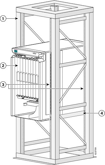
|
1 |
Equipment rack |
3 |
Vertical mounting brackets |
|
2 |
8-slot line card chassis |
4 |
Horizontal mounting brackets |
 Warning | The chassis should be mounted on a rack that is permanently affixed to the building. Statement 1049 |
 Note | We recommend that you use a scissor lift or similar lifting device to position the chassis in the rack and to hold the chassis in place while you bolt it to the rack. A forklift is not recommended for this purpose . |
As you plan the installation of the chassis into the equipment rack, consider the following:
- Make sure that the floor mounting bolts on the equipment rack are accessible, especially if annual retorquing of bolts is required.
- For chassis installation, you must have access to the vertical mounting rails at each corner of the equipment rack.
- Consider whether the area around the rack is large enough to accommodate the scissor lift (or similar lifting device) and installation personnel.
- A minimum of 48 mounting screws (10-32 x 5/8 in. socket head cap screws are provided with the chassis) are needed to secure the chassis to the rack. To secure the chassis to the rack, install twelve screws on each of the four vertical mounting brackets.
Note | If you plan to use mounting screws other than the ones shipped with the chassis, you can use 10-32, 10-24, 12-24, or M5 screws. (M6 and 1/4-20 screws do not fit.) |
- The rack should have horizontal shelf brackets to place the chassis on. The brackets must be able to support at least 650 lb. (294.8 kg). If the rack does not have horizontal mounting rails, a set of rails is included in the installation kit, which is available as an option (CRS-8-INSTALL-KT=).
 Caution | Standard rack-mounting screws are not strong enough to secure the chassis to the equipment rack. Use only those mounting screws that are shipped with the chassis or those listed in the Equipment Rack Specifications section. |
For complete instructions on mounting and securing the chassis to a rack, see the Cisco CRS Carrier Routing System 8-Slot Line Card Chassis Enhanced Router Unpacking, Moving, and Securing Guide .
Aisle Spacing and Maintenance Access Floor Plan
The floor plan for the Cisco CRS must include enough space to install the Cisco CRS 8-Slot Line Card Chassis Enhanced router in the equipment rack and allow sufficient airflow for the system. The floor plan must also provide enough room to access chassis components for maintenance (for example, to remove fan trays, power modules, cables, and air filters).
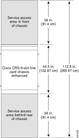
The following figure shows a top view of the Cisco CRS 8-Slot Line Card Chassis Enhanced router footprint required for installation.
Note | For chassis installation, make sure that enough room exists in front of the chassis to accommodate installation personnel and the scissor lift (or similar lifting device) used to hold the chassis in the rack while it is bolted in. |
Dimensions of the Cisco CRS 8-Slot Line Card Chassis Enhanced Router
The dimensions for the Cisco CRS 8-Slot Line Card Chassis Enhanced router are:
- Chassis depth (including front grille and optional front cover): 40.5 in. (102.9 cm)
- Chassis height: 38.5 in. (97.8 cm)
- Chassis width: 17.5 in. (44.5 cm).
Front and Rear Clearances
The site requires the following front and rear clearances for chassis installation and maintenance access:
- To install the chassis in the equipment rack: approximately 40 inches (101.6cm)
- To service components and allow system airflow (both in front of and behind the chassis): 36 inches (91.4 cm)
Note | Maintain at least 6 inches (15.2 cm) of clearance at both the inlet and exhaust openings on the chassis and on the power modules to allow sufficient airflow. |
Power and Cooling Requirements
See Power and Cooling for information about the power and cooling systems on the Cisco CRS 8-Slot Line Card Chassis Enhanced router and for information about the power and cooling requirements at the installation site.
System Console
A system console is required to configure the routing system for operation. As you plan your site facilities, make sure that the site has enough room for a system console and the console cable is long enough to reach the routing system.
Note | The console port does not support modem control or hardware flow control. The port requires a straight-through EIA/TIA-232 cable. |
Cable Management
As the size of the routing system increases, the cabling required for the chassis increases. For example, a fully loaded Cisco CRS 8-Slot Line Card Chassis Enhanced router has more cables connected to it than a partially loaded chassis. The cabling runs must be carefully planned. The basic configurations for various routing systems should be arranged to minimize the complexity and length of the cable runs. Precut and terminated cables are considered part of the basic configuration.
- CONSOLE or AUX RJ-45 RS-232 serial ports on the route processor cards for terminal connections
- Ethernet ports on the route processor cards for connecting network management equipment
- Modular service cards (MSCs) and physical layer interface modules (PLIMs) for data connections
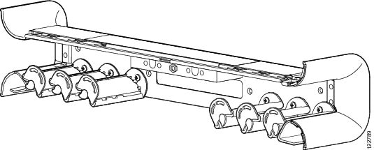
The cable-management bracket is for organizing these interface cables to keep the front of the chassis clear and to eliminate sharp bends in the cables.
Caution | Excessive bending can damage interface cables. |
The cable-management bracket has a special telescoping feature that allows the bracket to be extended when the chassis is upgraded with higher-density cards. This extension feature also helps in installing the cables in the chassis.
Note | When the telescoping feature is in use the front cover on the chassis cannot be installed. |
The following figure shows the chassis cable-management bracket.
Route Processor Cables
As you consider system cabling, see the following table to determine the types of cables required to connect to ports on the route processor (RP).
|
RP Port |
Required Cable Type |
||
|---|---|---|---|
|
Ethernet management |
|
||
|
Alarm |
Shielded cable. Required for EMC compliance. |
PLIM Interface Cables
You must provide the PLIM interface cables. Because the type and number of interfaces can vary, plan these cable runs prior to the installation. When planning the cable runs, consider the following:
- Number and type of interface connections (OC-48/STM-16 or STS-48, OC-192/STM-64 or STS-192, OC-768/STM-256 or STS-768, 10-Gigabit Ethernet, and 100-Gigabit Ethernet)
- Termination at the other end of the cables (such as patch panel or optical transport equipment)
- Proper length and termination of cables
Custom Cables
The installation site may require custom cables designed for the facilities. We can assist you in planning custom cables.
Noise Control
A routing system can generate large amounts of fan noise. The Cisco CRS 8-Slot Line Card Chassis Enhanced router has some built-in noise reduction, such as fan speed control. If the routing system is installed in an environment where excessive noise could be harmful to personnel, some other noise reduction options could be attempted. Passive noise reduction could include the installation of foam panels to insulate the surrounding area from the noise.
Additional noise-reduction measures have to be designed on an individual site basis.
Cisco Installation Services
Cisco or a Cisco partner can provide a complete installation, from planning to power up. For information about Cisco or Cisco partner installation services, consult Cisco Customer Advocacy.
System Testing, Certification, and Warranties
After the routing system has been installed, it must be tested and certified. Consult Cisco Customer Advocacy for information about testing, certification, and warranties.
 Feedback