Cisco IOS H.323 Configuration Guide, Release 15.1
Bias-Free Language
The documentation set for this product strives to use bias-free language. For the purposes of this documentation set, bias-free is defined as language that does not imply discrimination based on age, disability, gender, racial identity, ethnic identity, sexual orientation, socioeconomic status, and intersectionality. Exceptions may be present in the documentation due to language that is hardcoded in the user interfaces of the product software, language used based on RFP documentation, or language that is used by a referenced third-party product. Learn more about how Cisco is using Inclusive Language.
- Updated:
- July 28, 2009
Chapter: Basic H.323 Setup and Management
- Contents
- Prerequisites for Basic H.323 Setup and Management
- Restrictions for Basic H.323 Setup and Management
- How to Set Up and Manage Basic H.323 Features
- Managing Basic (Nonconfigurable) Gateway Features
- H.323 Signaling
- H.323 Call Statistics
- Source Call Signal Address
- Tunneling of Redirecting Number Information Element
- H.323 Call Redirection
- Multizone Features
- Codec Negotiation
- H.245 Empty Capabilities Set
- Lightweight Registration
- H.450.2 Call Transfer
- H.450.3 Call Deflection
- Gateway Support for a Network-Based Billing Number
- Answer Supervision Reporting
- Managing Basic (Nonconfigurable) Gatekeeper Features
- Managing Basic (Nonconfigurable) Gateway Features
Basic H.323 Setup and Management
This chapter describes nonconfigurable H.323 features.
Feature History for Gatekeeper Ecosystem Interoperability
|
|
|
12.1(1)T |
This feature was introduced. |
Feature History for Gatekeeper Management Statistics
|
|
|
12.2(15)T |
This feature was introduced, and the CISCO-GATEKEEPER-MIB was enhanced to display gatekeeper-management statistics. |
Feature History for Gateway-to-Gatekeeper Billing Redundancy
|
|
|
12.1(1)T |
This feature was introduced. |
Feature History for H.323 Call Redirection Enhancements
Feature History for H.323 Version 2 Enhancements
Finding Support Information for Platforms and Cisco IOS Software Images
Use Cisco Feature Navigator to find information about platform support and Cisco IOS software image support. Access Cisco Feature Navigator at http://www.cisco.com/go/fn. You must have an account on Cisco.com. If you do not have an account or have forgotten your username or password, click Cancel at the login dialog box and follow the instructions that appear.

Note ![]() For more information about these and other related Cisco IOS voice features, see the following:
For more information about these and other related Cisco IOS voice features, see the following:
•![]() "H.323 Overview" section on page 9
"H.323 Overview" section on page 9
•![]() For information about the full set of Cisco IOS voice features, see the entire Cisco IOS Voice Configuration Library—including library preface, glossary, and other documents—at http://www.cisco.com/en/US/docs/ios/12_3/vvf_c/cisco_ios_voice_configuration_library_glossary/vcl.htm
For information about the full set of Cisco IOS voice features, see the entire Cisco IOS Voice Configuration Library—including library preface, glossary, and other documents—at http://www.cisco.com/en/US/docs/ios/12_3/vvf_c/cisco_ios_voice_configuration_library_glossary/vcl.htm
Contents
•![]() Prerequisites for Basic H.323 Setup and Management
Prerequisites for Basic H.323 Setup and Management
•![]() Restrictions for Basic H.323 Setup and Management
Restrictions for Basic H.323 Setup and Management
•![]() How to Set Up and Manage Basic H.323 Features
How to Set Up and Manage Basic H.323 Features
Prerequisites for Basic H.323 Setup and Management
Prerequisites are described in the "Prerequisites for Configuring an H.323 Network" section on page 9.
Restrictions for Basic H.323 Setup and Management
Restrictions are described in the "Restrictions for Configuring an H.323 Network" section on page 10.
How to Set Up and Manage Basic H.323 Features
This section contains the following information:
•![]() Managing Basic (Nonconfigurable) Gateway Features
Managing Basic (Nonconfigurable) Gateway Features
•![]() Managing Basic (Nonconfigurable) Gatekeeper Features
Managing Basic (Nonconfigurable) Gatekeeper Features
Managing Basic (Nonconfigurable) Gateway Features
The following sections describe H.323 features on the gateway that do not require user configuration:
•![]() Tunneling of Redirecting Number Information Element
Tunneling of Redirecting Number Information Element
•![]() Gateway Support for a Network-Based Billing Number
Gateway Support for a Network-Based Billing Number
H.323 Signaling
When interworking with ISDN, with T-1 channel-associated signaling (CAS), and with E-1 R2 services from the PSTN, H.323 signaling enables VoIP networks to properly signal the setup and teardown of calls. In-band tones and announcements are generated as needed at the originating or terminating switch. When a tone is played at the destination switch, the backward voice path from the called party to the calling party is cut through early so that the calling party can hear the tone or announcement. To prevent fraudulent calls, the voice path is cut through in both directions only after the connect message is received from the destination. The call progress indicator, which signals the availability of in-band communication, is carried end to end as required when interworking with ISDN and CAS protocols.
The H.323 signaling feature prevents unexpected behavior, such as early alerting (when an alert message is returned immediately after a call proceeding message is sent), to ensure that the calling party does not hear conflicting call progress information, such as a ringback tone followed by a busy tone, and does not miss hearing a tone or announcement when one should play. Support for network-side ISDN and reduction in the risk of speech clipping is also addressed.
The H.323 signaling feature is dependent on Cisco H.323 gateways, gatekeepers, and VoIP features.
H.323 signaling provides the following capabilities:
End-to-End Alerting
Early alerting is prevented in these ways:
•![]() For calls that terminate at an ISDN switch—The terminating gateway sends an alert message to the originating gateway only after it receives an alert message from the terminating switch.
For calls that terminate at an ISDN switch—The terminating gateway sends an alert message to the originating gateway only after it receives an alert message from the terminating switch.
•![]() For calls that terminate at a CAS switch—The terminating gateway sends a progress message, rather than an alert message, to the originating gateway after it receives a setup message.
For calls that terminate at a CAS switch—The terminating gateway sends a progress message, rather than an alert message, to the originating gateway after it receives a setup message.
Cut-Through of Voice Path
When tones and announcements are generated at the destination switch, the backward voice path from the called party to the calling party is cut through before the tones and announcements are played. This allows announcements, such as "The number you have called has been changed," or allows tones for error conditions, such as network congestion, to be forwarded to the calling party. To prevent fraudulent calls, the originating gateway does not perform full cut-through until it receives a connect message from the destination switch. Cut-through is performed as follows:
•![]() For calls that terminate at an ISDN switch—The terminating gateway performs backward cut-through when it receives an alert or progress message and full cut-through (both directions) when it receives a connect message. The originating gateway performs backward cut-through when it receives a call proceeding message and full cut-through when it receives a connect message.
For calls that terminate at an ISDN switch—The terminating gateway performs backward cut-through when it receives an alert or progress message and full cut-through (both directions) when it receives a connect message. The originating gateway performs backward cut-through when it receives a call proceeding message and full cut-through when it receives a connect message.
•![]() For calls that terminate at a CAS switch—The terminating gateway performs backward cut-through after it sends a progress message and full cut-through (both directions) when it receives an off-hook signal. The originating gateway performs backward cut-through when it receives a progress message and full cut-through when it receives a connect message.
For calls that terminate at a CAS switch—The terminating gateway performs backward cut-through after it sends a progress message and full cut-through (both directions) when it receives an off-hook signal. The originating gateway performs backward cut-through when it receives a progress message and full cut-through when it receives a connect message.
Note ![]() If the originating or terminating gateway sends a call proceeding message and then receives a call proceeding message with a progress indicator of 1, 2, or 8, the gateway converts this call proceeding message into a progress message with a corresponding PI.
If the originating or terminating gateway sends a call proceeding message and then receives a call proceeding message with a progress indicator of 1, 2, or 8, the gateway converts this call proceeding message into a progress message with a corresponding PI.
H.245 Initiation
To avoid speech clipping, H.245 capabilities are now initiated at the originating gateway at the earliest possible moment, when the originating gateway receives a call proceeding message from the terminating gateway. Previously, call proceeding messages were not passed end to end across the VoIP network; H.245 was initiated only after the originating gateway received an alert message.
Overlap Dialing
To enhance overlap dialing, the call proceeding message is now passed transparently from the terminating switch to the originating switch if the originating switch does not include the sending complete information element in the setup message. The call proceeding message notifies the originating switch that the terminating switch has collected all dialed digits that are required to route the call. If the originating switch sends a sending complete IE, the originating gateway responds with a call proceeding message, and the session application drops the call proceeding message sent by the terminating switch.
H.323 Call Statistics
Beginning with Cisco IOS Release 12.2(4)T, enhancements to H.323 call statistics allow you to clear the gateway counters, display H.323 messages that have been sent and received, obtain statistics on the reasons calls are disconnected, and display debug output for various components within the H.323 subsystem. To enable these enhancements, the following commands are available: clear h323 gateway command, show h323 gateway command, and debug cch323 command.
Note ![]() Using any of the debug cch323 commands could slow your system and flood the TTY if there is significant call traffic.
Using any of the debug cch323 commands could slow your system and flood the TTY if there is significant call traffic.
The enhancements to H.323-call-statistics commands do not affect Cisco H.323 configurations. Therefore, there are no configuration tasks in this document.
To display and clear H.323 call statistics, use the following commands in privileged EXEC mode.
SUMMARY STEPS
1. ![]() clear h323 gateway [cause-code stats | h225 | ras]
clear h323 gateway [cause-code stats | h225 | ras]
2. ![]() show h323 gateway [cause-code stats | h225 | ras]
show h323 gateway [cause-code stats | h225 | ras]
3. ![]() debug cch323 {all | error | h225 | h245 | ras | rawmsg | session}
debug cch323 {all | error | h225 | h245 | ras | rawmsg | session}
Source Call Signal Address
Note ![]() To learn about restrictions that apply, see the "Source Call Signal Address and H.245 Empty Capabilities Set Restrictions" section on page 12.
To learn about restrictions that apply, see the "Source Call Signal Address and H.245 Empty Capabilities Set Restrictions" section on page 12.
Source call signal address allows a source call-signal address field to be included in the ARQ.
Previously, in the Cisco IOS implementation of H.323 gateway software, if the terminating gateway was registered to an H.323 gatekeeper and used RAS, the ARQ message sent for each incoming call did not contain the H.225 source call signal address (CSA). The source CSA is an optional parameter in the ARQ message. The source CSA is also an optional parameter in the H.225 call setup message sent by the originating endpoint.
source call signal address also allows for the source CSA parameter to be included in the ARQ message, as illustrated by the message sequence shown in Figure 1.
Figure 1 Source Call Signal Message Sequence
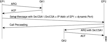
In the message sequence shown in Figure 1, the ARQ messages are enhanced to send the source CSA. The originating gateway (EP1) sends the H.225 setup message to the destination gateway. The setup message contains the source CSA parameter, which is the combination of the IP address of the originator and the dynamic TCP port number used or obtained for the H.225 call signaling channel. If the terminating gateway (EP2) accepts the call upon receipt of the setup message, the gateway sends an ARQ message to the gatekeeper. The terminating gateway retrieves the source CSA parameter sent by the originating gateway in the setup message. It then sends an ARQ message to the gatekeeper with the source CSA parameter. The CSA parameter is optional and has the same value as the source CSA in the received setup message. If the setup message does not contain the source CSA parameter, the terminating gateway determines the source CSA by using the H.225 call-signaling TCP socket connection of the peer endpoint, which it uses in the ARQ message.
If the originating gateway is registered to a gatekeeper and RAS is used as the session target, the originating gateway also sends an ARQ message. This ARQ does not include the optional source CSA parameter.
Tunneling of Redirecting Number Information Element
An incoming PRI setup message may contain either a Redirecting Number (RDN) Information Element (IE) or an Original Called Number (OCN) IE. These IEs indicate that the call has been redirected (forwarded) and that each message contains the following:
•![]() Destination number (DN) that was originally called
Destination number (DN) that was originally called
•![]() Reason for the call being redirected
Reason for the call being redirected
•![]() Other related information
Other related information
OCN IE is a Nortel variant of the RDN IE.
H.323 Version 2
H.323 Version 2 gateway passes the entire RDN or OCN IE from an incoming PRI message into the H.225 SETUP message. The IE is encapsulated in the nonStandardData field within the user-to-user information element (UUIE) of the H.225 SETUP message. The nonStandardData field can contain the encapsulated RDN or OCN IE and a tunneled global, signaling, and control standard QSIG message, or it can contain only the OCN or RDN. Cisco and other third-party H.323 endpoints can access the redirected information by decoding the nonStandardData field. In accordance with the H.225 specification, the nonStandardData is ignored by third-party endpoints and causes no interoperability problems.
For redirected PRI calls that are routed to a Cisco gateway, that are sent using H.323 to another Cisco gateway, and that exit the gateway using PRI, the RDN/OCN IE is tunneled from the source gateway to the destination gateway. The incoming PRI setup message is tunneled through H.225 and is encoded into the outgoing PRI setup message by the destination gateway.
Tunneling the RDN or OCN IE is important for applications such as Unified Messaging servers that need to know the telephone number that was originally dialed so as to access the correct account information.
H.323 Version 4
H.323 Version 4 introduces a standard-based RDN IE in the H.225 SETUP message in Cisco IOS Release 12.3(11)T. The RDN IE is sent as a Q.931 IE in the H.225 SETUP message. The nonStandardData RDN and OCN IE are still supported for backward compatibility. When both H.225 Q.931 RDN IE and nonStandardData IE are received, the RDN in the H.225 Q.931 is decoded and the nonStandardData is not decoded.
H.323 Call Redirection
The user-to-user information element (UUIE) of the Facility message is used primarily for call redirection. The UUIE contains a field, facilityReason, that indicates the nature of the redirection. The H.323 Call Redirection Enhancements feature adds support for two of the reasons: routeCallToGatekeeper and callForwarded. It also provides a nonstandard method for using the Facility message to effect call transfer.
Route Call to Gatekeeper
There are two situations in which the Cisco H.323 gateway might receive or generate a facility message with a routeCallToGatekeeper reason.
•![]() The gateway receives a facility message with routeCallToGatekeeper as a response to its H.225 SETUP message. Upon receiving the Facility message, the Cisco H.323 gateway attempts to route the call to the new gatekeeper, using the new IP address specified in the alternativeAddress field of the facility message.
The gateway receives a facility message with routeCallToGatekeeper as a response to its H.225 SETUP message. Upon receiving the Facility message, the Cisco H.323 gateway attempts to route the call to the new gatekeeper, using the new IP address specified in the alternativeAddress field of the facility message.
–![]() If the IP address is not available, the gateway ignores the facility message and sends a release complete toward the original destination end-point. The release complete message contains a ReleaseCompleteReason of facilityCallDeflection.
If the IP address is not available, the gateway ignores the facility message and sends a release complete toward the original destination end-point. The release complete message contains a ReleaseCompleteReason of facilityCallDeflection.
–![]() If the IP address is available, the gateway sends a disengage request (DRQ) message to the gatekeeper and waits for the disengage confirmation (DCF) message before it sends the SETUP message to the new destination gatekeeper.
If the IP address is available, the gateway sends a disengage request (DRQ) message to the gatekeeper and waits for the disengage confirmation (DCF) message before it sends the SETUP message to the new destination gatekeeper.
•![]() During the admission request (ARQ) phase of a call, a gatekeeper might determine that a call, which has come through an intermediate gateway, needs to be routed to another gatekeeper. The gatekeeper sends an admission rejection (ARJ) message with a RejectReason of routeCallToGatekeeper to the gateway. Upon receiving the message, the intermediate Cisco H.323 gateway sends a Facility message to the originator of the SETUP message. This message indicates that the SETUP message should be sent to another address. (The gateway includes the callSignalAddress from ARJ in the alternativeAddresss field of the Facility message.) Upon receiving the Facility message, the calling gateway terminates the initial call and sends a new SETUP message to the specified gatekeeper, using the new IP address specified in the alternativeAddress field of the facility message. If the callSignalAddress is not provided, the gateway does not send the Facility message and the call is terminated without any rerouting.
During the admission request (ARQ) phase of a call, a gatekeeper might determine that a call, which has come through an intermediate gateway, needs to be routed to another gatekeeper. The gatekeeper sends an admission rejection (ARJ) message with a RejectReason of routeCallToGatekeeper to the gateway. Upon receiving the message, the intermediate Cisco H.323 gateway sends a Facility message to the originator of the SETUP message. This message indicates that the SETUP message should be sent to another address. (The gateway includes the callSignalAddress from ARJ in the alternativeAddresss field of the Facility message.) Upon receiving the Facility message, the calling gateway terminates the initial call and sends a new SETUP message to the specified gatekeeper, using the new IP address specified in the alternativeAddress field of the facility message. If the callSignalAddress is not provided, the gateway does not send the Facility message and the call is terminated without any rerouting.
Call Forward
In certain cases, an H.323 endpoint might determine that a call needs to be forwarded. The endpoint then sends a Facility message to the gateway with a facilityReason of callForwarded. This message includes the address of the new destination (either an alternativeAddress or alternativeAliasAddress). Upon receiving the Facility message, the Cisco H.323 gateway sends a release complete to the original destination endpoint and initiates a new call using the new destination address supplied in the Facility message. The release complete message contains a ReleaseCompleteReason of facilityCallDeflection. If the gateway is registered with a gatekeeper, the gateway sends a DRQ to the gatekeeper and waits for the DCF before sending a setup message to the destination gatekeeper.
The Facility message must contain an E.164 address in the alternativeAliasAddress field. If no address is included, the Facility message is ignored. The E.164 is required because the call forwarding process initiates a new call, which may be subject to authentication processes that can handle only E.164 addresses.
If the Facility message contains both and IP address (in the alternativeAddress field) and an E.164 address (in the alternativeAliasAddress field), the gateway first attempts to find a match for the new E.164 and the dial-peer. If there is no match, the gateway uses the same incoming peer to determine if there is a matching peer to reroute the call. If there is no match to the incoming peer, the message is ignored.
Call Transfer
Note ![]() To learn about restrictions that apply, see the "Call Transfer Restrictions" section on page 12.
To learn about restrictions that apply, see the "Call Transfer Restrictions" section on page 12.
If a Facility message with a facilityReason of callForwarded is received after the call has been accepted, it is considered a call transfer. In this case, the Cisco H.323 gateway places the call on hold and initiates a new call using the address (alternativeAddress or alternativeAliasAddress) supplied in the Facility message.
As with call forwarding, the Facility message must contain an E.164 address in the alternativeAliasAddress field. If no address is included, the Facility message is ignored. The E164 is required because the call forwarding process initiates a new call, which may be subject to authentication processes that can handle only E.164 addresses.
If the Facility message contains both and IP address (in the alternativeAddress field) and an E.164 address (in the alternativeAliasAddress field), the gateway first attempts to find a match for the new E.164 and the dial-peer. If there is no match, the gateway uses the same incoming peer to determine if there is a matching peer to reroute the call. If there is no match to the incoming peer, the message is ignored.
Unlike in call forwarding case, the Facility message is accepted by both the called side and the originating side.
Note ![]() This use of call forwarded is not defined by ITU standard.
This use of call forwarded is not defined by ITU standard.
Multizone Features
Cisco multizone software enables the Cisco gateway to provide information to the gatekeeper using additional fields in the RAS messages. The gatekeeper no longer terminates a call if it is unable to resolve the destination E.164 phone number with an IP address.
Previously, the source gateway attempted to set up a call to a destination IP address as provided by the gatekeeper in an admission confirm (ACF) message. If the gatekeeper was unable to resolve the destination E.164 phone number to an IP address, the incoming call was terminated.
Multizone software allows a gatekeeper to provide additional destination information and modify the destinationInfo field in the ACF message. The gateway includes the canMapAlias-associated destination information in setting up the call to the destination gateway.
The gatekeeper indicates to the gateway that the call should be destined to a new E.164 number by sending an ACF message with an IP address of 10.0.0.0 in the destCallSignalAddress field and the new destination E.164 phone number in the destinationInfo field.
The gateway that receives such an ACF falls back to routing the call on the basis of this new E.164 address and performing another lookup of the configured dial plan for the gateway. If the gateway routes the call on the basis of the new E.164 address, the call might be routed back to the PSTN or to an H.323 endpoint.
Codec Negotiation
Codec negotiation allows the gateway to offer several codecs during the H.245 capability exchange phase and to ultimately settle on a single common codec during the call establishment phase. Offering several codecs increases the probability of establishing a connection because there is a greater chance of overlapping voice capabilities between endpoints. Normally, only one codec can be specified when a dial peer is configured, but codec negotiation allows a prioritized list of codecs associated with a dial peer to be specified. During call establishment, the router uses the highest-priority codec from the list that it has in common with the remote endpoint. It also adjusts to the codec selected by the remote endpoint so that a common codec is established for both the receive and send voice directions.
When a call is originated, all the codecs associated with the dial peer are sent to the terminating endpoint in the H.245 terminal capability set message. At the terminating endpoint, the gateway advertises all the codecs that are available in firmware in its terminal capability set. If there is a need to limit the codecs advertised to a subset of the available codecs, a terminating dial peer must be matched that includes this subset. The incoming called-number command in dial peer configuration mode can be used to force this match.
Supported codecs (Table 1) are available for use with Cisco H.323 Version 2 software.
Note![]() •
•![]() A separate codec for G.729 Annex B is included, which adds Annex B functionality to G.729. A separate codec for G.723.1 Annex A adds Annex A functionality to G.723.1.
A separate codec for G.729 Annex B is included, which adds Annex B functionality to G.729. A separate codec for G.723.1 Annex A adds Annex A functionality to G.723.1.
•![]() The Annex B functionality added to G.729 and the Annex A functionality added to G.723.1 are the built-in, codec-specific voice-activated detection/calling tone (VAD/CNG) functions.
The Annex B functionality added to G.729 and the Annex A functionality added to G.723.1 are the built-in, codec-specific voice-activated detection/calling tone (VAD/CNG) functions.
H.245 Empty Capabilities Set
Note ![]() To learn about restrictions that apply, see the "Source Call Signal Address and H.245 Empty Capabilities Set Restrictions" section on page 12.
To learn about restrictions that apply, see the "Source Call Signal Address and H.245 Empty Capabilities Set Restrictions" section on page 12.
Empty capabilities set support is a mandatory part of the H.323 Version 2 standard. It is used by applications to redirect the voice media stream. This feature is particularly useful for applications such as the following:
•![]() Selsius IP phones, which rely on a hub or call manager to direct the media stream to IP phones.
Selsius IP phones, which rely on a hub or call manager to direct the media stream to IP phones.
•![]() Unified messaging for which it is desirable to redirect the media stream to various message servers for message playout.
Unified messaging for which it is desirable to redirect the media stream to various message servers for message playout.
The empty capabilities set feature was added to provide a way to redirect RTP streams. The RTP streams are redirected as follows:
•![]() The sequence starts with the an empty capabilities set being received at an endpoint.
The sequence starts with the an empty capabilities set being received at an endpoint.
•![]() After an open logical channel (OLC) is established (or if in the middle of this process) one of the endpoints sends an empty capabilities set message.
After an open logical channel (OLC) is established (or if in the middle of this process) one of the endpoints sends an empty capabilities set message.
•![]() When the empty capabilities set message is received, the other endpoints close the logical channel if any was opened with that endpoint and move to a pause state, waiting for a nonempty capability set message.
When the empty capabilities set message is received, the other endpoints close the logical channel if any was opened with that endpoint and move to a pause state, waiting for a nonempty capability set message.
After receiving the nonempty capabilities set message, the endpoint moves to the beginning of Phase B, which is the initial communication and capabilities exchange, as described in H.323 Version 3 (June 1999), item 8.4.6.
In other words, the exchange of the capabilities message determines a master/slave relationship, and a new OLC message is created to open a new logical channel with another endpoint. From this point on, the RTP streams are sent to the new endpoint.
Lightweight Registration
Before the release of its H.323 Version 2 software, Cisco gateways reregistered with the gatekeeper every 30 seconds. Each registration renewal used the same process as the initial registration, even though the gateway was already registered with the gatekeeper. These registration renewals generated considerable overhead at the gatekeeper.
Cisco H.323 Version 2 software defines a lightweight registration procedure that still requires the full registration process for initial registration but that uses an abbreviated renewal procedure to update the gatekeeper and minimize overhead.
Lightweight registration requires each endpoint to specify a time-to-live (TTL) value in its registration request (RRQ) message. When a gatekeeper receives an RRQ message with a TTL value, it returns an updated TTL timer value in a registration confirmation (RCF) message to the endpoint. Shortly before the TTL timer expires, the endpoint sends an RRQ message with the KeepAlive field set to TRUE, which refreshes the existing registration.
It is not required that an H.323 Version 2 endpoint indicate a TTL in its registration request. If the endpoint does not indicate a TTL, the gatekeeper assigns one and sends it to the gateway in the RCF message. No configuration changes are permitted during a lightweight registration, so all fields other than the endpointIdentifier, gatekeeperIdentifier, tokens, and TTL are ignored. In the case of H.323 Version 1 endpoints that cannot process the TTL field in the RCF, the gatekeeper probes the endpoint with information requests (IRQs) for a predetermined grace period to see if the endpoint is still alive.
H.450.2 Call Transfer
Call transfer allows an H.323 endpoint to redirect an answered call to another H.323 endpoint. Cisco gateways support H.450.2 call transfer as the transferring and transferred-to party. The transferring endpoint must be an H.450-capable terminal; the Cisco gateway cannot act as the transferring endpoint. Gatekeeper-controlled or gatekeeper-initiated call transfer is not supported.
Note ![]() Certain devices are limited in their support of H.450. The Cisco 1700 and Cisco uBR820 platforms do not support IVR. Therefore, these platforms are not able to act as H.450 transferring endpoints.
Certain devices are limited in their support of H.450. The Cisco 1700 and Cisco uBR820 platforms do not support IVR. Therefore, these platforms are not able to act as H.450 transferring endpoints.
H.450.2 specifies two variants of call transfer:
•![]() Transfer without consultation—The transferring endpoint supplies the number of the transferred-to endpoint as part of the transfer request, and the two remote endpoints are transferred together. A Cisco gateway cannot be the transferring endpoint.
Transfer without consultation—The transferring endpoint supplies the number of the transferred-to endpoint as part of the transfer request, and the two remote endpoints are transferred together. A Cisco gateway cannot be the transferring endpoint.
•![]() Transfer with consultation—This feature is not currently supported.
Transfer with consultation—This feature is not currently supported.
H.450.3 Call Deflection
Call deflection is a feature under H.450.3 Call Diversion (Call Forwarding) that allows a called H.323 endpoint to redirect the unanswered call to another H.323 endpoint. Cisco gateways support H.450.3 call deflection as the originating, deflecting, and deflected-to gateway. The Cisco gateway as the deflecting gateway supports invocation of call deflection only by using an incoming PRI QSIG message (call deflection cannot be invoked by using any other trunk type).
If the deflecting endpoint is a Cisco gateway, the telephony endpoint on the PRI of the deflecting gateway invokes call deflection by sending an equivalent QSIG reroute invoke request within a FACILITY message to the gateway. The deflecting gateway then uses the procedures outlined in the H.450.3 call deflection standard to transfer the call to another endpoint. Note that the initiation of deflection using QSIG reroute invoke is valid only on calls that arrived as H.323 calls at the deflecting gateway. In other words, for calls that arrive at the gateway through a telephony interface (such as a hairpin call) or by using a non-H.323 IP protocol, QSIG reroute invoke is ignored.
Cisco H.323 Version 2 software does not support gatekeeper-controlled or gatekeeper-initiated call deflection.
Note ![]() Certain devices are limited in their support of the H.450 standard. The Cisco AS5800 is not able to convert QSIG to H.450. The Cisco 1700 and Cisco uBR820 do not support IVR. Therefore, these devices are not able to act as H.450 deflecting endpoints.
Certain devices are limited in their support of the H.450 standard. The Cisco AS5800 is not able to convert QSIG to H.450. The Cisco 1700 and Cisco uBR820 do not support IVR. Therefore, these devices are not able to act as H.450 deflecting endpoints.
Gateway Support for a Network-Based Billing Number
Gateway support for a network-based billing number informs the gatekeeper of the specific voice port or T1/E1 span from which an incoming call entered the ingress gateway. This is done using a Cisco-proprietary, nonstandard field that has been added to the ARQ message sent by the ingress gateway. No configuration is necessary for this feature.
Answer Supervision Reporting
Answer supervision reporting is an enhancement to the information request (IRR) Registration, Admission, and Status (RAS) protocol message that enables gatekeepers to maintain call accounting information by reporting the call connection time of connected calls to the gatekeeper.
In H.323 configurations, the endpoint (gateway) uses direct call-routed signaling. Gatekeepers do not have real-time knowledge or control over the state of a call and are dependent on the endpoints to provide them with necessary real-time information, such as call connect time, call termination time, and call termination reason.
When a call ends, the gateway sends a DRQ message with the BillingInformationToken (which contains the duration of the call) to the gatekeeper. If for some reason the gatekeeper does not receive the DRQ message, the gatekeeper does not have the information about when the call started or the duration of the call, which is necessary to maintain accounting information.
Answer supervision reporting allows the call connection time to be reported to the gatekeeper upon the connection of a call and at periodic intervals thereafter. Answer supervision reporting adds a proprietary Cisco parameter, the call connection time, to the perCallInfo parameter in the nonStandardData field, which is located in the IRR message. When a connect message is received, the originating gateway sends the unsolicited IRR message to its gatekeeper. On sending a connect message, the terminating gateway sends the unsolicited IRR message to its gatekeeper. If the ACF message has a nonzero value for the IRR frequency parameter, the gateway sends the unsolicited IRR message to its gatekeeper at periodic intervals, which are determined by the value in the IRRfrequency parameter.
With the exception of containing the call connection time in the perCallInfo parameter, the IRR message and its functionality remain the same.
Managing Basic (Nonconfigurable) Gatekeeper Features
The following sections describe H.323 features on the gateway that do not require user configuration:
•![]() Gateway-to-Gatekeeper Billing Redundancy
Gateway-to-Gatekeeper Billing Redundancy
•![]() Ecosystem Gatekeeper Interoperability
Ecosystem Gatekeeper Interoperability
•![]() Gatekeeper-Management Statistics
Gatekeeper-Management Statistics
Gateway-to-Gatekeeper Billing Redundancy
Gateway-to-gatekeeper billing enhances the accounting capabilities of the Cisco H.323 gateway and provides support for VocalTec™ gatekeepers. Gateway-to-gatekeeper billing redundancy provides for redundant billing information to be sent to an alternate gatekeeper if the primary gatekeeper to which a gateway is registered becomes unavailable.
During the process of establishing a call, the primary gatekeeper sends an ACF message to the registered gateway. The ACF message includes the billing information of the user and an access token. To provide the billing information to an alternate gatekeeper if the primary gatekeeper is unavailable when the call session ends, the access token information sent in the ACF message is also included in the DRQ message that is sent to the alternate gatekeeper.
This feature enables the alternate gatekeeper to obtain the billing information required to successfully complete the transaction.
Ecosystem Gatekeeper Interoperability
Note ![]() To learn about restrictions that apply, see the "Ecosystem Gatekeeper Interoperability Restrictions" section on page 12.
To learn about restrictions that apply, see the "Ecosystem Gatekeeper Interoperability Restrictions" section on page 12.
Ecosystem gatekeeper interoperability adds support for the alternate gatekeeper field (altGKInfo) in the gatekeeper rejection (GRJ), registration rejection (RRJ), and admission rejection (ARJ) messages. This allows a gateway to move between gatekeepers during the GRQ, RRQ, and ARQ phases. There is no need for gateway reconfiguration or for a gatekeeper failover in the gateway.
Gateways can be configured to switch from their primary gatekeeper to an alternate gatekeeper if a failure or outage occurs. If an outage occurs and gateways move from one gatekeeper to another, there may be an imbalance in the number of gateways registered to each gatekeeper. The ecosystem gatekeeper interoperability feature helps to restore the balance (when the outage has been corrected) by allowing some of the gateways to be moved back to their proper gatekeepers.
The altGKInfo consists of two subfields: the alternateGatekeeper and the altGKisPermanent flag. The alternateGatekeeper is the list of alternate gatekeepers. The altGKisPermanent is a flag that indicates whether the gatekeepers in the associated alternateGatekeeper field are permanent or temporary.
•![]() If the current state of the altGKisPermanent flag is TRUE, the new altGKInfo of any RAS message received from one of the alternate gatekeepers is accepted and the new list replaces the existing list.
If the current state of the altGKisPermanent flag is TRUE, the new altGKInfo of any RAS message received from one of the alternate gatekeepers is accepted and the new list replaces the existing list.
•![]() If the current state of the altGKisPermanent flag is FALSE, the altGKInfo of any RAS message received from one of the alternate gatekeepers is ignored.
If the current state of the altGKisPermanent flag is FALSE, the altGKInfo of any RAS message received from one of the alternate gatekeepers is ignored.
If the current permanent gatekeeper becomes nonresponsive and the altGKisPermanent flag is set to FALSE, the gateway sets the internal state of the altGKisPermanent flag to TRUE. This allows the gateway to accept the alternate gatekeeper list from one of the gatekeepers in the existing alternate gatekeeper list.
The handling of the altGKInfo field varies depending on whether it is included in a GRJ or an RRJ message.
AltGKInfo in GRJ Messages
When the gateway accepts the alternate gatekeeper list from the GRJ, the gateway sends a GRQ message to a gatekeeper on the list. The selection is based on priority of the alternate gatekeepers. Each alternate gatekeeper is tried until a GCF message is received.
If the gateway receives a GRJ message without the AltGKInfo field, it accepts the rejection. Because this is the first phase for the gateway to contact a gatekeeper, the gateway is considered lost without a gatekeeper.
During the GRQ phase, the gateway ignores the value of the altGKisPermanent flag in any RAS message and sets the value internally to TRUE.
AltGKInfo in RRJ Messages
When the gateway accepts the alternate gatekeeper list from the first RRJ message, the gateway retransmits an RRQ message to a gatekeeper on the alternate gatekeeper list. The selection is based on priority of the alternate gatekeepers.
The retransmission of the RRQ message depends on the type of RRQ (full or lightweight), the current state of the altGKisPermanent flag, and the current state of the needToRegister flag of each alternate gatekeeper as follows:
•![]() If the state of the altGKisPermanent flag is TRUE and the state of the needToRegister flag is NO, the gateway retransmits the full RRQ to an alternate gatekeeper for full RRQs and a lightweight RRQ for lightweight RRQs.
If the state of the altGKisPermanent flag is TRUE and the state of the needToRegister flag is NO, the gateway retransmits the full RRQ to an alternate gatekeeper for full RRQs and a lightweight RRQ for lightweight RRQs.
•![]() If the state of the altGKisPermanent flag is TRUE and the state of the needToRegister flag is YES, the gateway retransmits the full RRQ to an alternate gatekeeper for full RRQs and lightweight RRQs.
If the state of the altGKisPermanent flag is TRUE and the state of the needToRegister flag is YES, the gateway retransmits the full RRQ to an alternate gatekeeper for full RRQs and lightweight RRQs.
•![]() If the state of the altGKisPermanent flag is FALSE and the state of the needToRegister flag is NO, the gateway retransmits a lightweight RRQ for lightweight RRQs and nothing for full RRQs.
If the state of the altGKisPermanent flag is FALSE and the state of the needToRegister flag is NO, the gateway retransmits a lightweight RRQ for lightweight RRQs and nothing for full RRQs.
•![]() If the state of the altGKisPermanent flag is TRUE and the state of the needToRegister flag is YES, the gateway does not retransmit the RRQ.
If the state of the altGKisPermanent flag is TRUE and the state of the needToRegister flag is YES, the gateway does not retransmit the RRQ.
If the gateway receives an RRJ message without the AltGKInfo field, it accepts the rejection and returns to the GRQ phase. If the state of the altGKisPermanent flag is FALSE, the gateway sends the GRQ message to the original gatekeeper that sent the first RRJ. If the state of the altGKisPermanent flag is TRUE, the gateway sends the GRQ to the current gatekeeper.
If the current state of the altGKisPermanent flag is TRUE, then the next RAS message is sent to the new gatekeeper. Otherwise, the next RAS message is sent to the original gatekeeper.
If the gateway exhausts the list of alternate gatekeepers without receiving any response from an alternate gatekeeper, the gateway returns to the GRQ phase.
Note ![]() For more information on the Cisco ecosystem gatekeeper interoperability feature, see the "Configuring Alternate-Gatekeeper Support" section on page 48.
For more information on the Cisco ecosystem gatekeeper interoperability feature, see the "Configuring Alternate-Gatekeeper Support" section on page 48.
Gatekeeper-Management Statistics
Performance-management parameters provide gatekeeper-management statistics that may be used to monitor a network and troubleshoot problems on the network. Parameters provide statistics such as the following:
•![]() Number of calls that originate and terminate from a specific location
Number of calls that originate and terminate from a specific location
•![]() Number of ongoing calls
Number of ongoing calls
•![]() Aggregate messaging information per zone
Aggregate messaging information per zone
•![]() Equipment behavior
Equipment behavior
•![]() Registration and unregistration information
Registration and unregistration information
•![]() Counter information (such as location requests [LRQs]) to gauge the level of activity
Counter information (such as location requests [LRQs]) to gauge the level of activity
Statistics are counted when the Registration, Admission, and Status (RAS) messages are sent and received by the gatekeeper. They are in raw form and reflect only a count of messages. Retries or retransmissions are not counted.
There are two ways to monitor gatekeeper-management statistics:
•![]() Using the MIB module—The MIB module consists of a repository of characteristics and parameters that support the gatekeeper function. The MIB gathers statistics and responds to queries as specified by the Simple Network Management Protocol (SNMP). SNMP operations are supported on the object identifiers (OIDs) for the managed objects. These OIDs can configure, manage, or analyze aspects of SNMP operation. Gatekeeper-management statistics are supported by the CISCO-GATEKEEPER-MIB; parameters for this MIB are shown in a table that you can access on your network management station.
Using the MIB module—The MIB module consists of a repository of characteristics and parameters that support the gatekeeper function. The MIB gathers statistics and responds to queries as specified by the Simple Network Management Protocol (SNMP). SNMP operations are supported on the object identifiers (OIDs) for the managed objects. These OIDs can configure, manage, or analyze aspects of SNMP operation. Gatekeeper-management statistics are supported by the CISCO-GATEKEEPER-MIB; parameters for this MIB are shown in a table that you can access on your network management station.
•![]() Using the command-line interface as in the following steps.
Using the command-line interface as in the following steps.
Displaying and Clearing Gatekeeper-Management Statistics
To display and clear gatekeeper-management statistics, use the following commands beginning in global configuration mode.
Prerequisites
•![]() Perform the prerequisite tasks listed in the "Prerequisites for Configuring an H.323 Network" section on page 9.
Perform the prerequisite tasks listed in the "Prerequisites for Configuring an H.323 Network" section on page 9.
SUMMARY STEPS
1. ![]() show gatekeeper performance stats
show gatekeeper performance stats
2. ![]() clear h323 gatekeeper statistics
clear h323 gatekeeper statistics
3. ![]() show h323 gatekeeper statistics aggregate
show h323 gatekeeper statistics aggregate
Examples
The following sample output displays BASIC gatekeeper-management statistics.
Router# show gatekeeper performance stats
-----Gatekeeper Performance Statistics-----
Performance statistics captured since: 00:17:00 UTC Mon Mar 1 1993
Gatekeeper level Admission Statistics:
ARQs received: 1
ARQs received from originating endpoints: 0
ACFs sent: 1
ACFs sent to the originating endpoint: 0
ARJs sent: 0
ARJs sent to the originating endpoint: 0
ARJs sent due to overload: 0
Number of concurrent calls: 0
Number of concurrent originating calls: 0
Gatekeeper level Location Statistics:
LRQs received: 1
LRQs sent: 0
LCFs received: 0
LCFs sent: 1
LRJs received: 0
LRJs sent: 0
LRJs sent due to overload: 0
Gatekeeper level Registration Statistics:
RRJ due to overload: 0
Total Registered Endpoints: 1
Gatekeeper level Disengage Statistics:
DRQs received: 1
DRQs sent: 0
DCFs received: 0
DCFs sent: 1
DRJs received: 0
DRJs sent: 0
Load balancing events: 0
The following CUMULATIVE sample output is the same as for BASIC output; the difference is that the BASIC counters are cleared by the clear h323 gatekeeper statistics command, and CUMULATIVE counters are not.
Router# show gatekeeper performance stats zone name voip3-2600-2
Performance statistics for zone voip3-2600-2
-----Zone Level Performance Statistics-----
Performance statistics captured since: 00:17:00 UTC Mon Mar 1 1993
Zone level Admission Statistics:
ARQs received: 1
ARQs received from originating endpoints: 0
ACFs sent: 1
ACFs sent to the originating endpoint: 0
ARJs sent: 0
ARJs sent to the originating endpoint: 0
Number of concurrent total calls: 0
Number of concurrent originating calls: 0
Zone level Location Statistics:
LRQs received: 1
LRQs sent: 0
LCFs received: 0
LCFs sent: 1
LRJs received: 0
LRJs sent: 0
Zone level Registration Statistics:
Full RRQs received: 1
Light RRQs received: 574
RCFs sent: 576
RRJs sent: 0
Total Registered Endpoints: 1
Zone level UnRegistration Statistics:
URQs received: 0
URQs sent: 0
UCFs received: 0
UCFs sent: 0
URJs received: 0
URJs sent: 0
URQs sent due to timeout: 0
Zone level Disengage Statistics:
DRQs received: 1
DRQs sent: 0
DCFs received: 0
DCFs sent: 1
DRJs received: 0
DRJs sent: 0
Toll Fraud Prevention
When a Cisco router platform is installed with a voice-capable Cisco IOS software image, appropriate features must be enabled on the platform to prevent potential toll fraud exploitation by unauthorized users. Deploy these features on all Cisco router Unified Communications applications that process voice calls, such as Cisco Unified Communications Manager Express (CME), Cisco Survivable Remote Site Telephony (SRST), Cisco Unified Border Element (UBE), Cisco IOS-based router and standalone analog and digital PBX and public-switched telephone network (PSTN) gateways, and Cisco contact-center VoiceXML gateways. These features include, but are not limited to, the following:
•![]() Disable secondary dial tone on voice ports—By default, secondary dial tone is presented on voice ports on Cisco router gateways. Use private line automatic ringdown (PLAR) for foreign exchange office (FXO) ports and direct-inward-dial (DID) for T1/E1 ports to prevent secondary dial tone from being presented to inbound callers.
Disable secondary dial tone on voice ports—By default, secondary dial tone is presented on voice ports on Cisco router gateways. Use private line automatic ringdown (PLAR) for foreign exchange office (FXO) ports and direct-inward-dial (DID) for T1/E1 ports to prevent secondary dial tone from being presented to inbound callers.
•![]() Cisco router access control lists (ACLs)—Define ACLs to allow only explicitly valid sources of calls to the router or gateway, and therefore to prevent unauthorized Session Initiation Protocol (SIP) or H.323 calls from unknown parties to be processed and connected by the router or gateway.
Cisco router access control lists (ACLs)—Define ACLs to allow only explicitly valid sources of calls to the router or gateway, and therefore to prevent unauthorized Session Initiation Protocol (SIP) or H.323 calls from unknown parties to be processed and connected by the router or gateway.
•![]() Close unused SIP and H.323 ports—If either the SIP or H.323 protocol is not used in your deployment, close the associated protocol ports. If a Cisco voice gateway has dial peers configured to route calls outbound to the PSTN using either time division multiplex (TDM) trunks or IP, close the unused H.323 or SIP ports so that calls from unauthorized endpoints cannot connect calls. If the protocols are used and the ports must remain open, use ACLs to limit access to legitimate sources.
Close unused SIP and H.323 ports—If either the SIP or H.323 protocol is not used in your deployment, close the associated protocol ports. If a Cisco voice gateway has dial peers configured to route calls outbound to the PSTN using either time division multiplex (TDM) trunks or IP, close the unused H.323 or SIP ports so that calls from unauthorized endpoints cannot connect calls. If the protocols are used and the ports must remain open, use ACLs to limit access to legitimate sources.
•![]() Change SIP port 5060—If SIP is actively used, consider changing the port to something other than well-known port 5060.
Change SIP port 5060—If SIP is actively used, consider changing the port to something other than well-known port 5060.
•![]() SIP registration—If SIP registration is available on SIP trunks, turn on this feature because it provides an extra level of authentication and validation that only legitimate sources can connect calls. If it is not available, ensure that the appropriate ACLs are in place.
SIP registration—If SIP registration is available on SIP trunks, turn on this feature because it provides an extra level of authentication and validation that only legitimate sources can connect calls. If it is not available, ensure that the appropriate ACLs are in place.
•![]() SIP Digest Authentication—If the SIP Digest Authentication feature is available for either registrations or invites, turn this feature on because it provides an extra level of authentication and validation that only legitimate sources can connect calls.
SIP Digest Authentication—If the SIP Digest Authentication feature is available for either registrations or invites, turn this feature on because it provides an extra level of authentication and validation that only legitimate sources can connect calls.
•![]() Explicit incoming and outgoing dial peers—Use explicit dial peers to control the types and parameters of calls allowed by the router, especially in IP-to-IP connections used on CME, SRST, and Cisco UBE. Incoming dial peers offer additional control on the sources of calls, and outgoing dial peers on the destinations. Incoming dial peers are always used for calls. If a dial peer is not explicitly defined, the implicit dial peer 0 is used to allow all calls.
Explicit incoming and outgoing dial peers—Use explicit dial peers to control the types and parameters of calls allowed by the router, especially in IP-to-IP connections used on CME, SRST, and Cisco UBE. Incoming dial peers offer additional control on the sources of calls, and outgoing dial peers on the destinations. Incoming dial peers are always used for calls. If a dial peer is not explicitly defined, the implicit dial peer 0 is used to allow all calls.
•![]() Explicit destination patterns—Use dial peers with more granularity than .T for destination patterns to block disallowed off-net call destinations. Use class of restriction (COR) on dial peers with specific destination patterns to allow even more granular control of calls to different destinations on the PSTN.
Explicit destination patterns—Use dial peers with more granularity than .T for destination patterns to block disallowed off-net call destinations. Use class of restriction (COR) on dial peers with specific destination patterns to allow even more granular control of calls to different destinations on the PSTN.
•![]() Translation rules—Use translation rules to manipulate dialed digits before calls connect to the PSTN to provide better control over who may dial PSTN destinations. Legitimate users dial an access code and an augmented number for PSTN for certain PSTN (for example, international) locations.
Translation rules—Use translation rules to manipulate dialed digits before calls connect to the PSTN to provide better control over who may dial PSTN destinations. Legitimate users dial an access code and an augmented number for PSTN for certain PSTN (for example, international) locations.
•![]() Tcl and VoiceXML scripts—Attach a Tcl/VoiceXML script to dial peers to do database lookups or additional off-router authorization checks to allow or deny call flows based on origination or destination numbers. Tcl/VoiceXML scripts can also be used to add a prefix to inbound DID calls. If the prefix plus DID matches internal extensions, then the call is completed. Otherwise, a prompt can be played to the caller that an invalid number has been dialed.
Tcl and VoiceXML scripts—Attach a Tcl/VoiceXML script to dial peers to do database lookups or additional off-router authorization checks to allow or deny call flows based on origination or destination numbers. Tcl/VoiceXML scripts can also be used to add a prefix to inbound DID calls. If the prefix plus DID matches internal extensions, then the call is completed. Otherwise, a prompt can be played to the caller that an invalid number has been dialed.
•![]() Host name validation—Use the "permit hostname" feature to validate initial SIP Invites that contain a fully qualified domain name (FQDN) host name in the Request Uniform Resource Identifier (Request URI) against a configured list of legitimate source hostnames.
Host name validation—Use the "permit hostname" feature to validate initial SIP Invites that contain a fully qualified domain name (FQDN) host name in the Request Uniform Resource Identifier (Request URI) against a configured list of legitimate source hostnames.
•![]() Dynamic Domain Name Service (DNS)—If you are using DNS as the "session target" on dial peers, the actual IP address destination of call connections can vary from one call to the next. Use voice source groups and ACLs to restrict the valid address ranges expected in DNS responses (which are used subsequently for call setup destinations).
Dynamic Domain Name Service (DNS)—If you are using DNS as the "session target" on dial peers, the actual IP address destination of call connections can vary from one call to the next. Use voice source groups and ACLs to restrict the valid address ranges expected in DNS responses (which are used subsequently for call setup destinations).
For more configuration guidance, see the "Cisco IOS Unified Communications Toll Fraud Prevention" paper.
 Feedback