- Cisco IOS NetFlow Overview
- Cisco IOS NetFlow Features Roadmap
- Getting Started with Configuring NetFlow and NetFlow Data Export
-
- Configuring NetFlow and NetFlow Data Export
- Configuring NetFlow BGP Next Hop Support for Accounting and Analysis
- Configuring MPLS Egress NetFlow Accounting and Analysis
- Configuring SNMP and using the NetFlow MIB to Monitor NetFlow Data
- NetFlow Reliable Export With SCTP
- Detecting and Analyzing Network Threats With NetFlow
-
- Configuring NetFlow Aggregation Caches
- Using NetFlow Filtering or Sampling to Select the Network Traffic to Track
- NetFlow Layer 2 and Security Monitoring Exports
- Configuring MPLS-aware NetFlow
- Configuring NetFlow Multicast Accounting
- Configuring NetFlow Top Talkers using Cisco IOS CLI Commands or SNMP Commands
- Configuring SNMP and using the NetFlow MIB to Monitor NetFlow Data
- NetFlow v9 for IPv6
- NDE for VRF Interfaces
Cisco IOS NetFlow Configuration Guide, Release 12.2SR
Bias-Free Language
The documentation set for this product strives to use bias-free language. For the purposes of this documentation set, bias-free is defined as language that does not imply discrimination based on age, disability, gender, racial identity, ethnic identity, sexual orientation, socioeconomic status, and intersectionality. Exceptions may be present in the documentation due to language that is hardcoded in the user interfaces of the product software, language used based on RFP documentation, or language that is used by a referenced third-party product. Learn more about how Cisco is using Inclusive Language.
- Updated:
- December 26, 2006
Chapter: NDE for VRF Interfaces
- Finding Feature Information
- Contents
- Prerequisites for NDE for VRF Interfaces
- Restrictions for NDE for VRF Interfaces
- Information About NDE for VRF Interfaces
- How to Configure NDE for VRF Interfaces for an MPLS VPN
- Configuration Examples for NDE for VRF Interfaces
- Where to Go Next
- Additional References
- Feature Information for NDE for VRF Interfaces
NDE for VRF Interfaces
The NetFlow data export (NDE) for VRF Interfaces feature enables the creation and export of hardware NetFlow cache entries for traffic entering a router on the last multi-protocol label switching (MPLS) hop of an IPv4 MPLS virtual private network (VPN). The NDE for VRF Interfaces feature also ensures that the data collected in the hardware NetFlow cache for traffic that is received on an IPv4 interface configured for a per-site forwarding table (VRF) contains the routing information specific to the VRF.
Finding Feature Information
Your software release may not support all the features documented in this module. For the latest feature information and caveats, see the release notes for your platform and software release. To find information about the features documented in this module, and to see a list of the releases in which each feature is supported, see the "Feature Information for NDE for VRF Interfaces" section.
Use Cisco Feature Navigator to find information about platform support and Cisco IOS and Catalyst OS software image support. To access Cisco Feature Navigator, go to http://www.cisco.com/go/cfn. An account on Cisco.com is not required.
Contents
•![]() Prerequisites for NDE for VRF Interfaces
Prerequisites for NDE for VRF Interfaces
•![]() Restrictions for NDE for VRF Interfaces
Restrictions for NDE for VRF Interfaces
•![]() Information About NDE for VRF Interfaces
Information About NDE for VRF Interfaces
•![]() How to Configure NDE for VRF Interfaces for an MPLS VPN
How to Configure NDE for VRF Interfaces for an MPLS VPN
•![]() Configuration Examples for NDE for VRF Interfaces
Configuration Examples for NDE for VRF Interfaces
•![]() Feature Information for NDE for VRF Interfaces
Feature Information for NDE for VRF Interfaces
Prerequisites for NDE for VRF Interfaces
Your router must be running Cisco IOS release 12.2(33)SRB or later to configure the NDE for VRF Interfaces feature.
Restrictions for NDE for VRF Interfaces
The NDE for VRF Interfaces feature supports only IPv4 traffic.
When you configure the NDE for VRF Interfaces feature for a MPLS VPN, the router assigns a reserved VLAN ID to the MPLS VPN. This will limit the number of VLAN IDs available for other features that you configure on the router and that require VLAN IDs.
Information About NDE for VRF Interfaces
Before configuring the NDE for VRF Interfaces feature, you should understand the following concepts:
•![]() Example of an MPLS VPN Network
Example of an MPLS VPN Network
•![]() Analysis of Traffic Exiting the MPLS VPN Network with NetFlow
Analysis of Traffic Exiting the MPLS VPN Network with NetFlow
•![]() VRF Name as the Source Interface in the NetFlow Cache
VRF Name as the Source Interface in the NetFlow Cache
Example of an MPLS VPN Network
Figure 1 is an example of a simple MPLS virtual private network (VPN). Routers PE1 and PE2 are configured to support an MPLS VPN to carry the customer's traffic between the sites where routers CE1 and CE2 are located. Routers PE1 and PE2 use multi-protocol iBGP peers for routing traffic on the MPLS VPNs. The NDE for VRF Interfaces feature is applicable to routers PE1 and PE2 in this example.
Figure 1 Example of a simple MPLS VPN network
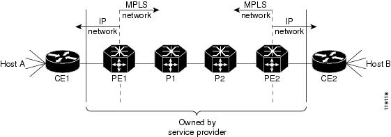
For more information about configuring MPLS on Cisco 7600 series routers, see the chapter Configuring PFC3BXL and PFC3B Multiprotocol Label Switching (MPLS) in the Cisco 7600 Series Cisco IOS Software Configuration Guide.
Analysis of Traffic Exiting the MPLS VPN Network with NetFlow
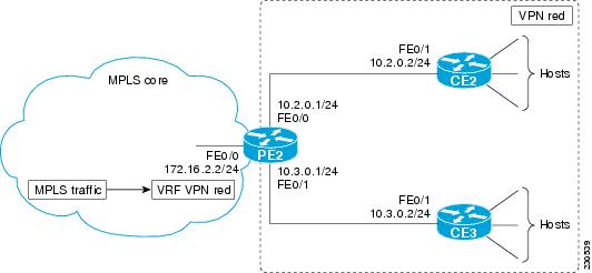
The NDE for VRF Interfaces feature captures traffic received by the router on the MPLS VPN VRF interface as it exits the MPLS network. For example, when you configure the NDE for VRF Interfaces feature on VPN Red on PE2 as shown in Figure 2, and the traffic to and from CE2 is assigned to VRF Red, the traffic is added to the NetFlow cache and shown as being received on VPN Red.
Figure 2 Example of a Router (PE2) Receiving Traffic over a MPLS VPN VRF Interface
MPLS Aggregate Labels
There are two types of VPN MPLS labels:
•![]() Aggregate labels for traffic on which a routing decision must be made
Aggregate labels for traffic on which a routing decision must be made
•![]() Non aggregate (specific) labels.
Non aggregate (specific) labels.
When you configure a MPLS VPN on a PE router the router allocates an aggregate MPLS label for the VPN.
Since aggregate MPLS labels correspond to the VRF to which a packet belongs, the router must consult the routing table for a VRF to determine the correct next hop IP address within the VPN domain in order to forward the packet. The next-hop IP address is required before the router can forward the packet because VPN domains are capable of supporting multiple next hop routers. For example, in Figure 2 there are two CE routers: CE2 and CE3. MPLS traffic arriving on VPN Red on PE1 could be destined to hosts attached to either CE2 or CE3. PE2 must perform another lookup to identify the correct CE router to which the traffic must be forwarded. The method that PE2 uses to perform the next-hop IP address lookup depends on the number of MPLS aggregate labels that the router has stored.
Stored MPLS Aggregate Labels
Traffic that uses one of the first 511 aggregate MPLS labels is forwarded by the router based on the entry for the MPLS VPN label in the VPN content addressable memory (CAM).
The following steps are performed by a PE router to forward MPLS traffic that uses one of the first 511 aggregate MPLS labels:
1. ![]() An MPLS packet carrying an aggregation label arrives at the egress PE router.
An MPLS packet carrying an aggregation label arrives at the egress PE router.
2. ![]() A lookup in the VPN CAM is performed for the MPLS aggregation label.
A lookup in the VPN CAM is performed for the MPLS aggregation label.
3. ![]() The MPLS aggregation label is removed and the corresponding VPN ID for the packet is identified.
The MPLS aggregation label is removed and the corresponding VPN ID for the packet is identified.
4. ![]() The index from the VPN CAM is used to reference the MPLS VPN routing table.
The index from the VPN CAM is used to reference the MPLS VPN routing table.
5. ![]() A lookup is performed for the destination IP prefix in the VPN VRF that was derived from the MPLS VPN table. The lookup result contains the next hop IP address and all other rewrite information needed for forwarding the packet to the correct CE router.
A lookup is performed for the destination IP prefix in the VPN VRF that was derived from the MPLS VPN table. The lookup result contains the next hop IP address and all other rewrite information needed for forwarding the packet to the correct CE router.
More Than 511 Stored MPLS Aggregate Labels
When the number of MPLS aggregate labels in the network exceeds 511, the router can no longer store some MPLS aggregate labels in its VPN CAM. In this situation the router consults the MPLS FIB, strips off the label to reveal the IPv4 packet encapsulated inside, and recirculates the packet, at which point the VRF FIB determines the next hop.

Note ![]() The first 511 MPLS aggregate labels remain in the VPN CAM and are processed based on the steps in the "Stored MPLS Aggregate Labels" section.
The first 511 MPLS aggregate labels remain in the VPN CAM and are processed based on the steps in the "Stored MPLS Aggregate Labels" section.
The following steps are performed by a PE router to forward MPLS traffic when the aggregate MPLS label is not in the VPN CAM:
1. ![]() A lookup is performed in the TCAM and FIB.
A lookup is performed in the TCAM and FIB.
2. ![]() The MPLS label is popped and the reserved VLAN associated with the MPLS aggregation label is assigned to the packet.
The MPLS label is popped and the reserved VLAN associated with the MPLS aggregation label is assigned to the packet.
Note ![]() When the number of MPLS aggregate labels exceeds 511, a reserved VLAN interface is assigned for each new MPLS aggregate label.
When the number of MPLS aggregate labels exceeds 511, a reserved VLAN interface is assigned for each new MPLS aggregate label.
3. ![]() The VPN ID for the reserved VLAN ID is derived from the VLAN RAM. The VPN ID is used as a part of the lookup key for the IP VRF Cisco express forwarding (CEF) lookup.
The VPN ID for the reserved VLAN ID is derived from the VLAN RAM. The VPN ID is used as a part of the lookup key for the IP VRF Cisco express forwarding (CEF) lookup.
4. ![]() The IP VRF CEF lookup result contains the next hop IP address and all other rewrite information needed for forwarding the packet to the correct CE router.
The IP VRF CEF lookup result contains the next hop IP address and all other rewrite information needed for forwarding the packet to the correct CE router.
NetFlow Cache Population
When the NDE for VRF Interfaces feature is configured for an MPLS VPN, a VLAN interface is reserved and NetFlow is enabled on the VLAN interface. The method used by the router to process the MPLS VPN IPv4 traffic and populate the NetFlow cache depends on the number of MLS aggregate labels that the router has stored.
MPLS Aggregate Labels in VPN CAM
When there are fewer than 512 VPN aggregate MPLS labels, the label and associated VPN are programmed in the MPLS VPN CAM, and packet recirculation is not required. The policy feature card (PFC) receives the packet as an IP packet. The PFC NetFlow function sees flows as sourced at the MPLS VPN not at the interface on which the traffic was received.
When there are fewer than 512 VPN aggregate MPLS labels (all MPLS aggregate labels are stored in the VPN CAM), the NetFlow cache is populated for the MPLS traffic that is using the MPLS aggregate labels by enabling NetFlow on the MPLS interface with the ip flow ingress command. For example, to enable NetFlow for the traffic that is being forwarded based on the MPLS aggregation labels in the VPN CAM in router PE2 in Figure 2, you must configure the ip flow ingress command on interface FastEthernet0/0. This is sufficient to populate the cache. To cause the router to export the NetFlow data to a collector, the flow hardware mpls-vpn ip vrf-id command must be issued in global configuration mode.
MPLS Aggregate Labels Not in VPN CAM
When the number of MPLS aggregate labels in the network exceeds 511, the VPN CAM is full. Traffic must be recirculated if it does not use one of the MPLS aggregate labels stored in the VPN CAM. The packets are processed by the policy feature card (PFC) once to strip the MPLS label, and processed by the PFC a second time with the VLAN specified as the reserved VPN VLAN that was assigned when the NDE for VRF Interfaces feature was enabled. The VLAN RAM maps this VLAN to the VPN for use in routing. The PFC netflow function sees flows as sourced at the reserved VRF VLAN. The ternary content addressable memory (TCAM) entry for the reserved VLAN interface provides the flow mask to NetFlow.
Flows for MPLS VPN traffic received with aggregate label that is not in the VPN CAM are populated in the NetFlow cache by configuring the flow hardware mpls-vpn ip vrf-id command for each VPN VRF on the router in global configuration mode.
MPLS-Specific Labels
For the nonaggregate label case, by definition, the router does not need to examine the underlying IP packet to determine where to route the packet. In order to cause the IP flows to populate the cache, the flow hardware mpls-vpn ip vrf-id configuration command must be entered. This causes the specific label flow traffic to be stripped of its label and recirculated to the reserved VPN VLAN prior to being forwarded to the exit interface. This introduces more delay in forwarding the traffic than would otherwise be experienced.
Configuring MPLS VPN Netflow Capture and Export
To ensure that you have enabled the capturing and export of NetFlow data for all of the traffic that you want to analyze, regardless of the MPLS aggregate label it is using, you should configure the ip flow ingress command on the MPLS interface and configure the flow hardware mpls-vpn ip vrf-id command for each VPN VRF on the router in global configuration mode.
Note ![]() The steps required to configure NetFlow data export (NDE) for data in the NetFlow cache are provided in the "How to Configure NDE for VRF Interfaces for an MPLS VPN" section.
The steps required to configure NetFlow data export (NDE) for data in the NetFlow cache are provided in the "How to Configure NDE for VRF Interfaces for an MPLS VPN" section.
VRF Name as the Source Interface in the NetFlow Cache
For traffic received for an MPLS VPN on an MPLS interface, the source interface for the traffic in the NetFlow cache is listed as the VPN name, not the physical interface on which the traffic was received. For example, traffic being received on FastEthernet0/0 on PE2 in Figure 2 will be displayed in the NetFlow cache on the router as being received over VPN Red, not interface FastEthernet0/0.
How to Configure NDE for VRF Interfaces for an MPLS VPN
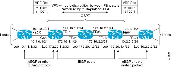
Perform this task to configure the NDE for VRF Interfaces feature on an MPLS VPN. This configuration is appropriate for the router named PE1 in Figure 3. Repeat this task on router PE2 but remember to change the interface references to the appropriate interfaces for PE2.
Note ![]() This task does not include the commands to configure open shortest path first (OSPF) and border gateway protocol (BGP) that are required to activate the MPLS VPN between routers PE1 and PE2. See the "Configuration Examples for NDE for VRF Interfaces" section for the complete configurations for all of the devices in the example network in Figure 3.
This task does not include the commands to configure open shortest path first (OSPF) and border gateway protocol (BGP) that are required to activate the MPLS VPN between routers PE1 and PE2. See the "Configuration Examples for NDE for VRF Interfaces" section for the complete configurations for all of the devices in the example network in Figure 3.
Figure 3 Example Network with One MPLS VPN
SUMMARY STEPS
1. ![]() enable
enable
2. ![]() configure terminal
configure terminal
3. ![]() ip vrf vrf-id
ip vrf vrf-id
4. ![]() rd route-distinguisher
rd route-distinguisher
5. ![]() route-target {import | export | both} route-target-ext-community
route-target {import | export | both} route-target-ext-community
6. ![]() interface type number
interface type number
7. ![]() ip address ip-address mask
ip address ip-address mask
8. ![]() exit
exit
9. ![]() mpls label protocol {ldp | tdp}
mpls label protocol {ldp | tdp}
10. ![]() mpls ldp router-id type number
mpls ldp router-id type number
11. ![]() interface type number
interface type number
12. ![]() ip address ip-address mask
ip address ip-address mask
13. ![]() mpls ip
mpls ip
14. ![]() ip flow ingress
ip flow ingress
15. ![]() interface type number
interface type number
16. ![]() ip vrf forwarding vrf-id
ip vrf forwarding vrf-id
17. ![]() ip address ip-address mask
ip address ip-address mask
18. ![]() exit
exit
19. ![]() mls nde sender
mls nde sender
20. ![]() mls flow ip {interface-destination-source | interface-full}
mls flow ip {interface-destination-source | interface-full}
21. ![]() ip flow-export version 9
ip flow-export version 9
22. ![]() ip flow-export destination {ip-address | hostname} udp-port
ip flow-export destination {ip-address | hostname} udp-port
23. ![]() flow hardware mpls-vpn ip vrf-id
flow hardware mpls-vpn ip vrf-id
DETAILED STEPS
Examples
The following output of the show mls nde command displays the NDE configuration and statistics.
PE1# show mls nde
Netflow Data Export enabled
Exporting flows to 172.16.2.6 (99)
Exporting flows from 172.16.1.2 (51203)
Version: 9
Layer2 flow creation is disabled
Layer2 flow export is disabled
Include Filter not configured
Exclude Filter not configured
Total Netflow Data Export Packets are:
4 packets, 0 no packets, 19 records
Total Netflow Data Export Send Errors:
IPWRITE_NO_FIB = 0
IPWRITE_ADJ_FAILED = 0
IPWRITE_PROCESS = 0
IPWRITE_ENQUEUE_FAILED = 0
IPWRITE_IPC_FAILED = 0
IPWRITE_OUTPUT_FAILED = 0
IPWRITE_MTU_FAILED = 0
IPWRITE_ENCAPFIX_FAILED = 0
Netflow Aggregation Disabled
PE1#
The following output of the show mls netflow ip module command displays the Netflow entries in the PFC. The first row of output shows traffic on VPN red.
Note ![]() Module 5 is the active supervisor 720 on this Cisco 7600 series router.
Module 5 is the active supervisor 720 on this Cisco 7600 series router.
Router# show mls netflow ip module 5
Displaying Netflow entries in module 5
DstIP SrcIP Prot:SrcPort:DstPort Src i/f :AdjPtr
-----------------------------------------------------------------------------
Pkts Bytes Age LastSeen Attributes
---------------------------------------------------
10.1.1.1 10.2.0.2 0 :0 :0 vpn:red :0x0
504 398020 1 23:20:48 L3 - Dynamic
224.0.0.5 172.16.1.1 89 :0 :0 Fa1/1 :0x0
1 84 7 23:20:42 L2 - Dynamic
0.0.0.0 0.0.0.0 0 :0 :0 -- :0x0
2238 1582910 33 23:20:48 L3 - Dynamic
224.0.0.2 172.16.1.1 udp :646 :646 Fa1/1 :0x0
5 310 21 23:20:46 L2 - Dynamic
172.16.2.6 172.16.1.2 0 :0 :0 Fa1/1 :0x0
1 140 22 23:20:27 L2 - Dynamic
Router#
The following output of the show ip cache flow command displays the data in the NetFlow cache. The last line of data in the output shows that the source interface for this traffic is VPN Red.
PE1# show ip cache flow
-------------------------------------------------------------------------------
MSFC:
IP packet size distribution (3139 total packets):
1-32 64 96 128 160 192 224 256 288 320 352 384 416 448 480
.000 .685 .309 .000 .000 .000 .000 .003 .000 .000 .000 .000 .000 .000 .000
512 544 576 1024 1536 2048 2560 3072 3584 4096 4608
.000 .000 .000 .000 .000 .000 .000 .000 .000 .000 .000
IP Flow Switching Cache, 278544 bytes
2 active, 4094 inactive, 56 added
20904 ager polls, 0 flow alloc failures
Active flows timeout in 30 minutes
Inactive flows timeout in 15 seconds
IP Sub Flow Cache, 33992 bytes
0 active, 1024 inactive, 4 added, 4 added to flow
0 alloc failures, 0 force free
1 chunk, 2 chunks added
last clearing of statistics never
Protocol Total Flows Packets Bytes Packets Active(Sec) Idle(Sec)
-------- Flows /Sec /Flow /Pkt /Sec /Flow /Flow
TCP-BGP 10 0.0 1 49 0.0 0.0 15.3
TCP-other 6 0.0 2 49 0.0 4.5 15.5
UDP-other 28 0.0 74 63 0.1 320.5 12.7
IP-other 6 0.0 153 80 0.0 1488.3 1.7
Total: 50 0.0 60 68 0.2 358.6 12.2
SrcIf SrcIPaddress DstIf DstIPaddress Pr SrcP DstP Pkts
Fa1/1 172.16.1.1 Null 224.0.0.2 11 0286 0286 74
Fa1/1 172.16.1.1 Null 224.0.0.5 59 0000 0000 33
-------------------------------------------------------------------------------
PFC:
Displaying Hardware entries in Module 5
SrcIf SrcIPaddress DstIPaddress Pr SrcP Dss
Fa1/1 172.20.1.2 172.20.1.3 0 0 0
Fa1/1 172.20.1.3 172.20.1.2 0 0 0
Fa1/1 172.16.1.2 172.16.2.6 0 0 0
Fa1/1 172.16.1.1 224.0.0.2 udp 646 64
-- 0.0.0.0 0.0.0.0 0 0 0
vpn:red 10.2.0.2 10.1.1.1 0 0 0
.
.
.
PE1#
Configuration Examples for NDE for VRF Interfaces
The following configuration example shows how to configure a simple network topology with the NDE for VRF Interfaces feature configured on two PE routers.
This section contains the following example configurations:
•![]() Configurations for the Example Network with One MPLS VPN: Example
Configurations for the Example Network with One MPLS VPN: Example
•![]() Configuring the NDE for VRF Interfaces Feature on a VRF: Example
Configuring the NDE for VRF Interfaces Feature on a VRF: Example
Configurations for the Example Network with One MPLS VPN: Example
This section contains the configurations for all of the devices in Figure 3. The NDE for VRF Interfaces feature is configured on routers PE1 and PE2.
CE1
!
hostname CE1
!
ip cef
!
interface Loopback0
no shutdown
ip address 10.1.1.1 255.255.255.255
!
interface FastEthernet0/0
no shutdown
ip address 10.1.0.2 255.255.255.0
!
ip default-network 0.0.0.0
ip route 0.0.0.0 0.0.0.0 10.1.0.1
!
end
PE1
!
hostname PE1
!
ip cef distributed
!
mls nde sender
mls flow ip interface-destination-source
ip flow-export destination 172.16.2.6 99
ip flow-export version 9
!
ip vrf red
rd 200:2
route-target export 200:20
route-target import 200:20
!
flow hardware mpls-vpn ip red
!
multilink bundle-name authenticated
mpls label protocol ldp
!
interface Loopback0
ip address 172.20.1.2 255.255.255.255
!
interface gigabitEthernet5/2
no shutdown
ip vrf forwarding red
ip address 10.1.0.1 255.255.255.0
!
interface FastEthernet1/1
no shutdown
interface FastEthernet1/1
ip address 172.16.1.2 255.255.255.0
ip flow ingress
mpls ip
!
router ospf 100
router-id 172.20.1.2
log-adjacency-changes
network 172.16.0.0 0.0.255.255 area 0
network 172.20.1.2 0.0.0.0 area 0
!
router bgp 200
no synchronization
bgp log-neighbor-changes
network 172.0.0.0 mask 255.0.0.0
neighbor as200 peer-group
neighbor as200 remote-as 200
neighbor as200 description as200
neighbor as200 update-source Loopback0
neighbor as200 route-reflector-client
neighbor 172.20.1.4 remote-as 200
neighbor 172.20.1.4 description iBGP with r4
neighbor 172.20.1.4 update-source Loopback0
no auto-summary
!
address-family vpnv4
neighbor 172.20.1.4 activate
neighbor 172.20.1.4 send-community both
exit-address-family
!
address-family ipv4 vrf red
no synchronization
network 10.1.0.0 mask 255.255.255.0
network 10.1.1.1 mask 255.255.255.255
exit-address-family
!
ip route 172.0.0.0 255.0.0.0 Null0
ip route vrf red 10.1.1.1 255.255.255.255 10.1.0.2
!
mpls ldp router-id Loopback0
!
end
P1
!
hostname P1
!
ip cef
!
no ip domain lookup
!
mpls label protocol ldp
!
interface Loopback0
no shutdown
ip address 172.20.1.3 255.255.255.255
!
interface FastEthernet0/0
no shutdown
ip address 172.16.2.1 255.255.255.0
mpls ip
!
interface FastEthernet0/1
no shutdown
ip address 172.16.1.1 255.255.255.0
mpls ip
!
router ospf 100
router-id 172.20.1.3
log-adjacency-changes
network 172.16.0.0 0.0.255.255 area 0
network 172.20.1.3 0.0.0.0 area 0
!
mpls ldp router-id Loopback0
!
end
PE2
!
hostname PE2
!
ip cef distributed
!
mls nde sender
mls flow ip interface-destination-source
ip flow-export destination 172.16.2.6 99
ip flow-export version 9
!
ip vrf red
rd 200:2
route-target export 200:20
route-target import 200:20
!
flow hardware mpls-vpn ip red
!
multilink bundle-name authenticated
mpls label protocol ldp
!
interface Loopback0
no shutdown
ip address 172.20.1.4 255.255.255.255
!
interface FastEthernet0/0
no shutdown
ip address 172.16.2.2 255.255.255.0
mpls ip
ip flow ingress
!
interface FastEthernet0/1
no shutdown
ip vrf forwarding red
ip address 10.2.0.1 255.255.255.0
!
router ospf 100
router-id 172.20.1.4
log-adjacency-changes
network 172.16.0.0 0.0.255.255 area 0
network 172.20.1.4 0.0.0.0 area 0
!
router bgp 200
no synchronization
bgp log-neighbor-changes
network 172.0.0.0 mask 255.0.0.0
neighbor as200 peer-group
neighbor as200 remote-as 200
neighbor as200 description as200
neighbor as200 update-source Loopback0
neighbor as200 route-reflector-client
neighbor 172.20.1.2 remote-as 200
neighbor 172.20.1.2 description iBGP with r2
neighbor 172.20.1.2 update-source Loopback0
no auto-summary
!
address-family vpnv4
neighbor 172.20.1.2 activate
neighbor 172.20.1.2 send-community both
exit-address-family
!
address-family ipv4 vrf red
no synchronization
network 10.2.0.0 mask 255.255.255.0
network 10.2.2.2 mask 255.255.255.255
exit-address-family
!
ip route 172.0.0.0 255.0.0.0 Null0
ip route vrf red 10.2.2.2 255.255.255.255 10.2.0.2
!
mpls ldp router-id Loopback0
!
end
CE2
!
hostname CE2
!
ip cef
!
interface Loopback0
no shutdown
ip address 10.2.2.2 255.255.255.255
!
interface FastEthernet0/1
no shutdown
ip address 10.2.0.2 255.255.255.0
!
ip default-network 0.0.0.0
ip route 0.0.0.0 0.0.0.0 10.2.0.1
!
end
Configuring the NDE for VRF Interfaces Feature on a VRF: Example
This example configuration shows how to configure the NDE for VRF Interfaces feature for a VRF. When you enable NetFlow on interface GigabitEthernet2/3 with the ip flow ingress command, the NetFlow cache will contain information for traffic for VPN vpn1.
PE1
!
ip vrf vpn1
rd 100:1
route-target export 100:1
route-target import 100:1
!
mls flow ip interface-full
!
interface GigabitEthernet2/3
ip vrf forwarding vpn1
ip address 10.0.0.1 255.0.0.0
ip flow ingress
!
interface GigabitEthernet2/7
ip vrf forwarding vpn1
ip address 172.16.20.1 255.255.255.0
!
ip flow-export version 9
ip flow-export destination 192.168.10.2 20000
end
Where to Go Next
•![]() See the Configuring NetFlow and NDE chapter of the Cisco 7600 Series Cisco IOS Software Configuration Guide, for more information on configuring NetFlow features on Cisco 7600 series routers.
See the Configuring NetFlow and NDE chapter of the Cisco 7600 Series Cisco IOS Software Configuration Guide, for more information on configuring NetFlow features on Cisco 7600 series routers.
•![]() See the Configuring PFC3BXL and PFC3B Mode Multiprotocol Label Switching (MPLS) chapter of the Cisco 7600 Series Cisco IOS Software Configuration Guide, for more information on configuring MPLS features on Cisco 7600 series routers.
See the Configuring PFC3BXL and PFC3B Mode Multiprotocol Label Switching (MPLS) chapter of the Cisco 7600 Series Cisco IOS Software Configuration Guide, for more information on configuring MPLS features on Cisco 7600 series routers.
Additional References
The following sections provide references related to the NDE for VRF Interfaces feature.
Related Documents
Standards
|
|
|
|---|---|
No new or modified standards are supported by this feature, and support for existing standards has not been modified by this feature. |
— |
MIBs
RFCs
|
|
|
|---|---|
No new or modified RFCs are supported by this feature, and support for existing RFCs has not been modified by this feature. |
— |
Technical Assistance
Feature Information for NDE for VRF Interfaces
Table 1 lists the release history for this feature.
Not all commands may be available in your Cisco IOS software release. For release information about a specific command, see the command reference documentation.
Use Cisco Feature Navigator to find information about platform support and software image support. Cisco Feature Navigator enables you to determine which Cisco IOS and Catalyst OS software images support a specific software release, feature set, or platform. To access Cisco Feature Navigator, go to http://www.cisco.com/go/cfn. An account on Cisco.com is not required.
Note ![]() Table 1 lists only the Cisco IOS software release that introduced support for a given feature in a given Cisco IOS software release train. Unless noted otherwise, subsequent releases of that Cisco IOS software release train also support that feature.
Table 1 lists only the Cisco IOS software release that introduced support for a given feature in a given Cisco IOS software release train. Unless noted otherwise, subsequent releases of that Cisco IOS software release train also support that feature.
|
|
|
|
|---|---|---|
NDE for VRF Interfaces |
12.2(33)SRB |
The NDE support for VRF interfaces features enables capturing and exporting NetFlow flow information from VRF interfaces. In 12.2(33)SRB, this feature was introduced on the Cisco 7600 series routers. The following sections provide information about this feature: • • The following commands were introduced or modified by this feature: flow hardware mpls-vpn ip, show ip cache flow, show ip cache flow aggregation, show mls netflow ip. |
 Feedback