Cisco IOS XE Dial Technologies Configuration Guide, Release 2
Bias-Free Language
The documentation set for this product strives to use bias-free language. For the purposes of this documentation set, bias-free is defined as language that does not imply discrimination based on age, disability, gender, racial identity, ethnic identity, sexual orientation, socioeconomic status, and intersectionality. Exceptions may be present in the documentation due to language that is hardcoded in the user interfaces of the product software, language used based on RFP documentation, or language that is used by a referenced third-party product. Learn more about how Cisco is using Inclusive Language.
- Updated:
- August 3, 2007
Chapter: Configuring Protocol Translation and Virtual Asynchronous Devices
- Protocol Translation Overview
- Creating Virtual Asynchronous Interfaces
- Enabling Protocol Translation of PPP and SLIP on Virtual Asynchronous Interfaces
- Enabling IPX-PPP over X.25 to an IPX Network on Virtual Terminal Lines
- Enabling Dynamic Routing on Virtual Asynchronous Interfaces
- Enabling TCP/IP Header Compression on Virtual Asynchronous Interfaces
- Enabling Keepalive Updates on Virtual Asynchronous Interfaces
- Setting an MTU on Virtual Asynchronous Interfaces
- Enabling PPP Authentication on Virtual Asynchronous Interfaces
- Enabling PPP Authentication via TACACS on Virtual Asynchronous Interfaces
- Basic Configuration Example
- Central Site Protocol Translation Example
- Decreasing the Number of Translation Sessions Example
- Increasing the Number of Translation Sessions Example
- LAT-to-LAT over an IP WAN Example
- LAT-to-LAT over Frame Relay or SMDS Example
- LAT-to-LAT Translation over a WAN Example
- LAT-to-LAT over an X.25 Translation Example
- LAT-to-TCP Translation over a WAN Example
- LAT-to-TCP over X.25 Example
- LAT-to-X.25 Host Configuration Example
- Local LAT-to-TCP Translation Example
- Local LAT-to-TCP Configuration Example
- Standalone LAT-to-TCP Translation Example
- Tunneling SLIP Inside TCP Example
- Tunneling PPP over X.25 Example
- X.25 to L2F PPP Tunneling Example
- Assigning Addresses Dynamically for PPP Example
- Local IP Address Pool Example
- X.29 Access List Example
- X.3 Profile Example
- X.25 PAD-to-LAT Configuration Example
- X.25 PAD-to-TCP Configuration Example
- One-Step Method for TCP-to-X.25 Host Connections Example
- Using the Two-Step Method for TCP-to-PAD Connections Example
- Two-Step Protocol Translation for TCP-to-PAD Connections Example
- Changing Parameters and Settings Dynamically Example
- Monitoring Protocol Translation Connections Example
- Two-Step Protocol Translation for Virtual Terminal Asynchronous Interfaces Example
Configuring Protocol Translation and Virtual Asynchronous Devices
This chapter describes how to configure protocol translation and virtual asynchronous connections using Cisco IOS software. These tasks are described in the following sections, which also describe the process of tunneling and protocol translation, and the two-step and the one-step translation methods:
•![]() Protocol Translation Overview
Protocol Translation Overview
•![]() Protocol Translation Configuration Task List
Protocol Translation Configuration Task List
•![]() Changing the Number of Supported Translation Sessions
Changing the Number of Supported Translation Sessions
•![]() Configuring Tunneling of SLIP, PPP, or ARA
Configuring Tunneling of SLIP, PPP, or ARA
•![]() Configuring X.29 Access Lists
Configuring X.29 Access Lists
•![]() Creating an X.29 Profile Script
Creating an X.29 Profile Script
•![]() Protocol Translation and Processing PAD Calls
Protocol Translation and Processing PAD Calls
•![]() Increasing or Decreasing the Number of Virtual Terminal Lines
Increasing or Decreasing the Number of Virtual Terminal Lines
•![]() Enabling Asynchronous Functions on Virtual Terminal Lines
Enabling Asynchronous Functions on Virtual Terminal Lines
•![]() Maintaining Virtual Interfaces
Maintaining Virtual Interfaces
•![]() Monitoring Protocol Translation Connections
Monitoring Protocol Translation Connections
•![]() Troubleshooting Protocol Translation
Troubleshooting Protocol Translation
•![]() Virtual Template for Protocol Translation Examples
Virtual Template for Protocol Translation Examples
•![]() Protocol Translation Application Examples
Protocol Translation Application Examples
•![]() Protocol Translation Session Examples
Protocol Translation Session Examples
The X.3 packet assembler/disassembler (PAD) parameters are described in the "X.3 PAD Parameters" appendix later in this publication.
The protocol translation facility assumes that you understand how to use the configuration software. Before using this chapter, you should be familiar with configuring the protocols for which you want to translate: X.25, Telnet, local-area transport (LAT), TN3270, AppleTalk Remote Access (ARA), PPP, Serial Line Internet Protocol (SLIP), and XRemote.

Note ![]() Telnet is a remote terminal protocol that is part of the TCP/IP suite. The descriptions and examples in the following sections use the term TCP as a reference to Telnet functionality.
Telnet is a remote terminal protocol that is part of the TCP/IP suite. The descriptions and examples in the following sections use the term TCP as a reference to Telnet functionality.
To identify the hardware platform or software image information associated with a feature, use the Feature Navigator on Cisco.com to search for information about the feature or refer to the software release notes for a specific release. For more information, see the "Identifying Supported Platforms" section in the "Using Cisco IOS Software" chapter.
For a complete description of the commands in this chapter, refer to the Cisco IOS Terminal Services Command Reference, Release 12.2. To locate documentation of other commands that appear in this chapter, use the command reference master index or search online.
Protocol Translation Overview
This section describes the additional tasks required to perform protocol translation from one host to another host or to a router. It includes the following sections:
•![]() Definition of Protocol Translation
Definition of Protocol Translation
•![]() Deciding Whether to Use One-Step or Two-Step Protocol Translation
Deciding Whether to Use One-Step or Two-Step Protocol Translation
•![]() One-Step Protocol Translation
One-Step Protocol Translation
•![]() Two-Step Protocol Translation
Two-Step Protocol Translation
•![]() Setting Up Virtual Templates for Protocol Translation
Setting Up Virtual Templates for Protocol Translation
Definition of Protocol Translation
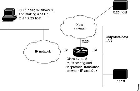
The protocol translation feature provides transparent protocol translation between systems running different protocols. It enables terminal users on one network to access hosts on another network, despite differences in the native protocol stacks associated with the originating device and the targeted host.
Protocol translation is a resourceful facility for many business applications. For example, Figure 29 shows a remote PC dialing through an IP network and connecting to an X.25 host. The TCP packets on the PC undergo a TCP-to-X.25 protocol translation by the Cisco 4700-M router.
Figure 29 Protocol Translation Business Application
Definition of Tunneling
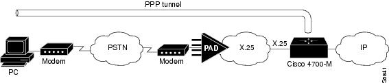
Unlike other protocols such as LAT, X.25, and TCP, which are actually translated when you use protocol translation, SLIP, PPP, and ARA are not translated to the destination protocol. Instead, they are carried inside a LAT, X.25, TCP, or Layer 2 Forwarding Protocol (L2F) tunnel specific to the device on the remote network. However, the protocol translation facility is used to enable tunneling of SLIP, PPP, or ARA.
Figure 30 shows a typical tunneling scenario.
Figure 30 Tunneling X.25 with PPP Across an IP Network
You can also tunnel PPP-IPX over X.25, TCP, or LAT to an Internetwork Packet Exchange (IPX) network when tunneling PPP on virtual terminal lines.
Deciding Whether to Use One-Step or Two-Step Protocol Translation
The Cisco IOS software supports virtual terminal connections in both directions between the following protocols. You can configure the router to translate automatically between them. This translation method is called one-step translation, and is more popular than the two-step method.
•![]() X.25 and LAT
X.25 and LAT
•![]() X.25 and Telnet sessions using the TCP
X.25 and Telnet sessions using the TCP
•![]() LAT and TCP/Telnet
LAT and TCP/Telnet
On outgoing connections, you can also use the one-step protocol translation facility to tunnel SLIP or PPP to IP and IPX networks, or ARA to AppleTalk networks across X.25, LAT, or IP (on outgoing connections only).
Cisco IOS software supports limited connections in both directions between the following protocols. Connecting between these protocols requires that you first connect to a router, then to the host to which you want to connect. This translation method is called two-step translation, and is the less popular method.
•![]() XRemote to SLIP/PPP and X.25 PAD environments (XRemote must use the two-step method)
XRemote to SLIP/PPP and X.25 PAD environments (XRemote must use the two-step method)
•![]() LAT, X.25, SLIP/PPP, and TCP (Telnet) to TN3270 (TN3270 must use the two-step method)
LAT, X.25, SLIP/PPP, and TCP (Telnet) to TN3270 (TN3270 must use the two-step method)
One-Step Protocol Translation
Use the one-step method when network users repeatedly log in to the same remote network hosts through a router. This connection is more efficient than the two-step method and enables the device to have more knowledge of the protocols in use because the router acts as a network connection rather than as a terminal. The one-step method provides transparent protocol conversion. When connecting to the remote network host, the user enters the connection command to the remote network host but does not need to specify protocol translation. The network administrator has already created a configuration that defines a connection and the protocols to be translated. The user performs only one step to connect with the host.
When you make a one-step connection to the router, the Cisco IOS software determines which host the connection is for and which protocol that host is using. It then establishes a new network connection using the protocol required by that host.
A disadvantage of the one-step protocol translation method is that the initiating computer or user does not know that two networking protocols are being used. This limitation means that parameters of the foreign network protocols cannot be changed after connections are established. The exception to this limitation is any set of parameters common to both networking protocols. Any parameter common to both can be changed from the first host to the final destination.
To configure the one-step method of protocol translation, set up the following protocols and connection options in the configuration file:
•![]() The incoming connection—The configuration includes the protocol to be used—LAT, X.25, or TCP/IP (Telnet)—the address, and any options such as reverse charging or binary mode that are supported for the incoming connection.
The incoming connection—The configuration includes the protocol to be used—LAT, X.25, or TCP/IP (Telnet)—the address, and any options such as reverse charging or binary mode that are supported for the incoming connection.
•![]() The outgoing connection—The outgoing connection is defined in the same way as the incoming connection, except that SLIP, PPP (including IP and IPX on PPP sessions), and ARA are also supported.
The outgoing connection—The outgoing connection is defined in the same way as the incoming connection, except that SLIP, PPP (including IP and IPX on PPP sessions), and ARA are also supported.
•![]() The connection features global options—You can specify additional features for the connection to allow, for example, incoming call addresses to match access list conditions or limit the number of users that can make the connection.
The connection features global options—You can specify additional features for the connection to allow, for example, incoming call addresses to match access list conditions or limit the number of users that can make the connection.
Refer to the section "Protocol Translation Configuration Task List" later in this chapter for configuration tasks.
Two-Step Protocol Translation
Use two-step protocol translation for one-time connections or when you use the router as a general-purpose gateway between two types of networks (for example, X.25 public data network (PDN) and TCP/IP). As with the one-step method, we recommend that you configure virtual templates for this feature.
Note ![]() You must use the two-step method for translations of TN3270 and XRemote.
You must use the two-step method for translations of TN3270 and XRemote.
With the two-step connection process, you can modify the parameters of either network connection, even while a session is in process. This process is similar to connecting a group of terminal lines from a PAD to a group of terminal lines from a TCP server. The difference is that you do not encounter the wiring complexity, unreliability, management problems, and performance bottlenecks that occur when two devices are connected via asynchronous serial lines.
Refer to the section "Protocol Translation Configuration Task List" later in this chapter for configuration tasks.
Tunneling SLIP, PPP, and ARA
Unlike other protocols such as LAT, X.25, and TCP, which actually are translated when you use one-step protocol translation, SLIP, PPP, and ARA are not translated to the destination protocol. Instead, they are carried inside a LAT, X.25, or TCP tunnel specific to the device on the remote network. However, you use the protocol translation facility to enable tunneling of SLIP, PPP, or ARA.
You can also tunnel IPX-PPP over X.25, TCP, or LAT, to an IPX network when tunneling PPP on virtual terminal lines. Refer to the section "Configuring Tunneling of SLIP, PPP, or ARA" later in this chapter for configuration tasks.
One-Step Tunneling of SLIP, PPP, and ARA
To use one-step protocol translation to tunnel SLIP, PPP (or IPX-PPP), or ARA, you need not enter any preliminary commands. Simply use the translate command with the slip or ppp keyword for one-step SLIP or PPP connections or the autocommand arap command for one-step ARA connections. Because ARA does not use addressing, you must specify the autocommand keyword, then specify the string arap to tunnel ARA to an AppleTalk network.
If you are tunneling PPP, SLIP, or ARA across X.25, you must also set up your X.3 profile correctly using the x29 profile command, as described in the section "Configuring One-Step Tunneling of SLIP or PPP" later in this chapter.
Two-Step Tunneling of PPP and SLIP
To tunnel SLIP or PPP across an X.25 WAN to an IP network using the two-step protocol translation method, use the vty-async command, which enables you to run PPP and SLIP on virtual terminal lines. Normally, PPP and SLIP function only on physical asynchronous interfaces. The vty-async command enables you to run PPP and SLIP on virtual terminal lines, which permits you to tunnel from an incoming protocol to SLIP or PPP and then to an IP network (or IPX-PPP to an IPX network).
If you make a PAD connection to a router running protocol translation and then issue the ppp definitions command to connect across an X.25 network, you also must set up your X.3 profile using the pad [/profile name] command.
Two-Step Tunneling of ARA
To tunnel ARA using the two-step method, you configure ARA on one or more virtual terminal lines and then configure automatic protocol startup. When a user connects to the vty and receives an EXEC prompt, ARA starts up automatically on the outgoing vty.
Setting Up Virtual Templates for Protocol Translation
The Cisco IOS software simplifies the process of configuring protocol translation to tunnel PPP or SLIP across X.25, TCP, and LAT networks. It does so by providing virtual interface templates that you can configure independently and apply to any protocol translation session. You can configure virtual interface templates for one-step and two-step protocol translation.
A virtual interface template is an interface that exists just inside the router (it is not a physical interface). You can configure virtual interface templates just as you do regular asynchronous serial interfaces. You then apply these virtual interface templates for one-step and two-step protocol translation (the process is described in detail in the section "Protocol Translation Configuration Task List" in this chapter). When a user dials in through a vty and a tunnel connection is established, the router clones the attributes of the virtual interface template onto a virtual access interface. This virtual access interface is a temporary interface that supports the asynchronous protocol configuration specified in the virtual interface template. This virtual access interface is created dynamically and lasts only as long as the tunnel session is active.
Before virtual templates were implemented, you enabled asynchronous protocol functions on virtual terminal lines by creating virtual asynchronous interfaces rather than virtual access interfaces. (For one-step translation, you did so by specifying ppp or slip as outgoing options in the translate command. For two-step translation, you did so by specifying the vty-async command.) The differences between virtual asynchronous interfaces and virtual access interfaces are as follows:
•![]() Virtual asynchronous interfaces are allocated permanently, whereas virtual access interfaces are created dynamically when a user calls in, and are closed down when the connection drops.
Virtual asynchronous interfaces are allocated permanently, whereas virtual access interfaces are created dynamically when a user calls in, and are closed down when the connection drops.
•![]() Virtual asynchronous interfaces were unconfigurable and supported only a limited set of protocol translation functions. However, virtual access interfaces are fully configurable via the virtual interface template. All attributes of the virtual interface template are cloned onto the virtual access interface when a call comes in.
Virtual asynchronous interfaces were unconfigurable and supported only a limited set of protocol translation functions. However, virtual access interfaces are fully configurable via the virtual interface template. All attributes of the virtual interface template are cloned onto the virtual access interface when a call comes in.
Virtual access interfaces replace virtual asynchronous interfaces for both one-step and two-step translation.
You can configure up to 25 virtual interface templates and have up to 300 virtual access interfaces per router (300 is the hardware limit on the router, based on the number of IDBs).
Note ![]() You can configure only a single virtual interface template (which applies to all virtual terminal asynchronous lines) when tunneling PPP or SLIP using two-step protocol translation.
You can configure only a single virtual interface template (which applies to all virtual terminal asynchronous lines) when tunneling PPP or SLIP using two-step protocol translation.
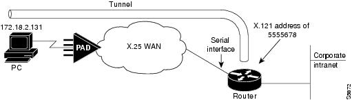
Figure 31 shows a typical network diagram for a tunnel session from a PC across an X.25 network, through a router set up with a virtual interface template for protocol translation, and to a corporate intranet.
Figure 31 PPP Tunnel Session Across an X.25 Network
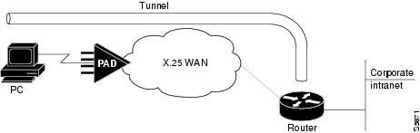
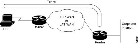
Figure 32 shows a typical network diagram for a tunnel session from a PC across a TCP or LAT WAN, through a router set up with a virtual interface template for protocol translation, and to a corporate intranet.
Figure 32 PPP Tunnel Session Across a TCP or LAT WAN
The virtual interface template service for protocol translation provides the following benefits:
•![]() Allows customized configurations to be predefined in one location, then applied dynamically to any protocol translation session, whether one-step or two-step, for easier maintenance.
Allows customized configurations to be predefined in one location, then applied dynamically to any protocol translation session, whether one-step or two-step, for easier maintenance.
•![]() Simplifies the translate command syntax by reducing the number of options required within each command.
Simplifies the translate command syntax by reducing the number of options required within each command.
•![]() Makes virtual asynchronous interfaces configurable for both one-step and two-step protocol translation.
Makes virtual asynchronous interfaces configurable for both one-step and two-step protocol translation.
Virtual Templates and L2F
L2F tunneling technology is used in virtual private dialup networks (VPDNs). VPDN allows separate and autonomous protocol domains to share common access infrastructure including modems, access servers, and ISDN routers by the tunneling of link level frames.
L2F/VPDN over protocol translation virtual template interfaces allows services with multiple X.25 dial point of presences (POPs) to expand their current L2F services. This ability can be accomplished by terminating the PPP virtual-asynchronous connections over X.25 at the Cisco protocol translation/router and setting up the L2F tunnel to the home gateway. With this configuration, protocol-level packets are allowed to pass through the virtual tunnel between endpoints of a point-to-point connection.
Typical L2F tunneling use includes Internet service providers (ISPs) or other access service creating virtual tunnels to link to the remote sites of a customer or remote users with corporate home networks. In particular, a network access server at the POP for the ISP exchanges PPP messages with the remote users, and communicates by L2F requests and responses with the home gateway of the customer to set up tunnels.
Frames from the remote users are accepted by the POP, stripped of any linked framing or transparency bytes, encapsulated in L2F, and forwarded over the appropriate tunnel. The home gateway of the customer accepts these L2F frames, strips the L2F encapsulation, and processes the incoming frames for the appropriate interface.
Note ![]() This implementation of VPDN supports PPP dialup only.
This implementation of VPDN supports PPP dialup only.
For more information on VPDNs, refer to the chapters in the part "Virtual Private Networks" in the Cisco IOS Dial Technologies Configuration Guide, Release 12.2.
Protocol Translation Configuration Task List
To configure protocol translation, perform the tasks described in the following sections as needed:
•![]() Configuring One-Step Protocol Translation (As Required)
Configuring One-Step Protocol Translation (As Required)
•![]() Configuring a Virtual Template for One-Step Protocol Translation (As Required)
Configuring a Virtual Template for One-Step Protocol Translation (As Required)
•![]() Configuring Two-Step Protocol Translation (As Required)
Configuring Two-Step Protocol Translation (As Required)
•![]() Configuring a Virtual Template for Two-Step Protocol Translation (As Required)
Configuring a Virtual Template for Two-Step Protocol Translation (As Required)
Refer to the sections "Virtual Template for Protocol Translation Examples," "Protocol Translation Application Examples," and "Protocol Translation Session Examples" later in this chapter for examples of protocol translation sessions and configurations.
Configuring One-Step Protocol Translation
To create one-step protocol translation connection specifications, use the following command in global configuration mode:
|
|
|
|---|---|
Router(config)# translate protocol incoming-address |
Creates the connection specifications for one-step protocol translation. |
For incoming PAD connections, the router uses a default PAD profile to set the remote X.3 PAD parameters unless a profile script is defined in the translate command. To override the default PAD profile the router uses, you must create a PAD profile script using the x29 profile global configuration command. In the following example, default is the name of the default PAD profile script and parameter:value is the X.3 PAD parameter number and value separated by a colon.
x29 profile default parameter:value [parameter:value]
Note ![]() If the X.29 profile is named default, it is applied to all incoming X.25 PAD calls, including the calls used with protocol translation.
If the X.29 profile is named default, it is applied to all incoming X.25 PAD calls, including the calls used with protocol translation.
Configuring a Virtual Template for One-Step Protocol Translation
To configure a virtual interface template to enable tunneling of PPP or SLIP across an X.25, TCP, or LAT WAN, first create and configure a virtual interface template, then apply it as the single outgoing option to the translate command.
Virtual interface templates in general support all commands available on any serial interface, because virtual templates are used for purposes other than protocol translation. However, a virtual access interface—which clones the configuration of the corresponding virtual interface template when created for protocol translation—supports only asynchronous protocol commands.
To enable tunneling of PPP or SLIP across an X.25, TCP, or LAT WAN by using one-step protocol translation, use the following commands beginning in global configuration mode:
|
|
|
|
|---|---|---|
Step 1 |
Router(config)# interface virtual-template number |
Creates a virtual interface template, and enters interface configuration mode. |
Step 2 |
|
Assigns an IP address to the virtual interface template. |
Step 3 |
|
Enables encapsulation on the virtual interface template. |
Step 4 |
|
Assigns an IP address from a pool to the device connecting to the virtual access interface (such as the PC in Figure 31). |
Step 5 |
|
Exits to global configuration mode. |
Step 6 |
Router(config)# translate {lat | tcp | x25} incoming-address [in-options] virtual-template number [global-options] |
Assigns the virtual interface template to a protocol translation session. |
1 You can also assign a specific IP address by using the ip address command, though assigning the IP address of the Ethernet 0 interface as shown is most common. 2 Virtual interface templates use PPP encapsulation by default, so you need not specify encapsulation ppp. However, to use SLIP encapsulation, you must explicitly specify encapsulation slip. |
Rather than specify outgoing translation options in the translate command, configure these options as interface configuration commands under the virtual interface template, then apply the virtual interface template to the translate command. Table 7 maps outgoing translate command options to interface commands you can configure in the virtual interface template.
Configuring Two-Step Protocol Translation
To translate using the two-step method, use the following commands in EXEC mode. The first step is required only if you are tunneling SLIP or PPP using the two-step protocol translation facility.
The Cisco IOS software supports the two-step method in both directions for protocols other than PPP and SLIP (for example, from Telnet to PAD, and vice versa).
Note ![]() PPP and SLIP are supported on outgoing connections only.
PPP and SLIP are supported on outgoing connections only.
Configuring a Virtual Template for Two-Step Protocol Translation
If you are tunneling PPP or SLIP using two-step protocol translation with virtual interface templates, you still use the vty-async command, just as before implementation of virtual templates. However, virtual asynchronous interfaces are not created as they were before virtual interface templates. Virtual access interfaces are created dynamically when a tunnel connection is established.
To create and configure a virtual interface template and apply it to a two-step protocol translation session, use the following commands beginning in global configuration mode:
|
|
|
|
|---|---|---|
Step 1 |
Router(config)# interface virtual-template number |
Creates a virtual interface template, and enters interface configuration mode. |
Step 2 |
|
Assigns an IP address to the virtual interface template. |
Step 3 |
|
Enables encapsulation on the virtual interface template. |
Step 4 |
|
Assigns an IP address from a pool to the device connecting to the virtual access interface (such as the PC in Figure 31). |
Step 5 |
|
Exits to global configuration mode. |
Step 6 |
Router(config)# vty-async |
Creates a virtual asynchronous interface. |
Step 7 |
Router(config)# vty-async virtual-template number |
Applies the virtual template to the virtual asynchronous interface. |
1 You can also assign a specific IP address by using the ip address address command, though assigning the IP address of the Ethernet0 interface as shown is most common. 2 Virtual interface templates use PPP encapsulation by default, so you need not specify encapsulation ppp. However, to use SLIP encapsulation, you must explicitly specify encapsulation slip. |
Other asynchronous configuration commands can be added to the virtual template configuration. We recommend that you include security on your virtual interface template. For example, you can enter the ppp authentication chap command.
Changing the Number of Supported Translation Sessions
There is a one-to-one relationship between protocol translation sessions and virtual terminal lines. For every session, you need a vty. Therefore, if you need to increase the number of protocol translation sessions, you need to increase the number of virtual terminal lines. That is, if your router has ten virtual terminal lines, you can have up to ten protocol translation sessions. The default number of virtual terminal lines is 5 (lines 0 through 4).
To increase the number of lines, and thus the maximum number of protocol translation sessions, use the following commands as needed, beginning in global configuration mode:
Protocol translation is a CPU-intensive task. Increasing the number of protocol translation sessions while routing is enabled can impact available memory. The amount of memory available depends on the platform type, the amount of DRAM available, the activity of each translation session, and the speed of the link. If you are using the maximum number of sessions and have problems with memory, you might need to decrease the number of protocol translation sessions.
Configuring Tunneling of SLIP, PPP, or ARA
To configure SLIP, PPP, or ARA tunneling, perform the tasks described in the following sections:
•![]() Configuring One-Step Tunneling of SLIP or PPP (As Required)
Configuring One-Step Tunneling of SLIP or PPP (As Required)
•![]() Configuring a Virtual Template for One-Step Protocol Translation (As Required)
Configuring a Virtual Template for One-Step Protocol Translation (As Required)
•![]() Configuring Two-Step Tunneling of SLIP or PPP (As Required)
Configuring Two-Step Tunneling of SLIP or PPP (As Required)
•![]() Enabling Dynamic Address Assignment for Outgoing PPP and SLIP on Virtual Terminal Lines (As Required)
Enabling Dynamic Address Assignment for Outgoing PPP and SLIP on Virtual Terminal Lines (As Required)
You can also enable IPX over tunneled PPP sessions.
Configuring One-Step Tunneling of SLIP or PPP
To tunnel SLIP or PPP using the one-step protocol translation facility, use the following commands in global configuration mode:
If you are configuring PPP over X.25 and do not know which X.3 profile parameters to use, try the following (these parameters do not function in all cases; they are simply a place from which to start):
1:0, 2:0, 3:2, 4:1, 5:0, 6:0, 7:21, 8:0, 9:0, 10:0, 11:14, 12:0, 13:0, 14:0, 15:0, 16:127, 17:24, 18:18, 19:0, 20:0, 21:0, 22:0
For more information about creating an X.29 profile script, refer to the section "Creating an X.29 Profile Script" later in this chapter. For an example of configuring PPP over X.25, see the section "Tunneling PPP over X.25 Example" at the end of this chapter.
To configure an outgoing session for IPX-PPP, use the ipx loopback number command for the outgoing session.
To tunnel SLIP or PPP across X.25, LAT, or Telnet using the one-step method, you need not enter any additional commands, as you do when you tunnel SLIP or PPP using the two-step method. The translate command enables asynchronous protocol features on one vty at a time.
PPP and SLIP, including IPX-PPP, can be tunneled on outgoing connections only.
Configuring One-Step Tunneling of ARA
To tunnel ARA using the one-step protocol translation facility, use the following commands beginning in global configuration mode. The first four steps are required; steps 5 through 11 are optional:
Configuring Two-Step Tunneling of SLIP or PPP
To tunnel SLIP or PPP using the two-step protocol translation facility, use the following commands beginning in global configuration mode:
If you want to configure IPX over your PPP sessions on virtual terminal lines, refer to the chapter "Configuring Asynchronous SLIP and PPP" in the Cisco IOS Dial Technologies Configuration Guide, Release 12.2.
Enabling Dynamic Address Assignment for Outgoing PPP and SLIP on Virtual Terminal Lines
You can specify IP addresses dynamically from a Dynamic Host Configuration Protocol (DHCP) proxy client or a local IP address pool on outgoing PPP and SLIP sessions on virtual terminal lines.
Assigning IP Addresses Using DHCP
The DHCP client-proxy feature manages a pool of IP addresses available to PPP or SLIP dial-in clients that need not know an IP address to be able to access a system. This feature allows a finite number of IP addresses to be reused quickly and efficiently by many clients. Additional benefits include the ability to maintain sessions, such as Telnet, even when a modem line fails. When the client is autodialed back into the access server or router, the session can be resumed because the same IP address is reissued to the client by the access server or router.
A DHCP proxy client is a Cisco access server or router configured to arbitrate DHCP calls between a DHCP server and a DHCP client. For more information about DHCP proxy clients, refer to the Cisco IOS IP Configuration Guide, Release 12.2.
To assign IP addresses using DHCP, use the following commands in global configuration mode:
The name argument is the name of the DHCP proxy client specified with the ip address-pool dhcp-proxy-client command.
Assigning IP Addresses Using Local IP Address Pooling
To make temporary IP addresses available for outgoing PPP and SLIP clients on outgoing sessions, you must first specify that the Cisco IOS software use a local IP address pool on all asynchronous interfaces and create one or more local IP address pools. You then assign local pooling as part of the translate command. To assign IP addresses dynamically on a virtual asynchronous connection, use the following commands in global configuration mode:
The scope-name option takes the name of any local IP address pool that has been defined using the ip local pool command.
Configuring X.29 Access Lists
Cisco IOS software provides access lists to limit access to a router from certain X.25 hosts. Access lists take advantage of the message field defined by Recommendation X.29, which describes procedures for exchanging data between two PADs or between a PAD and a DTE device.
To define X.29 access lists, perform the tasks described in these sections:
•![]() Creating an X.29 Access List (Required)
Creating an X.29 Access List (Required)
•![]() Applying an Access List to a Virtual Line (Required)
Applying an Access List to a Virtual Line (Required)
Note ![]() When configuring protocol translation, you can specify an access list number with each translate command. In the case of translation sessions that result from incoming PAD connections, the corresponding X.29 access list is used.
When configuring protocol translation, you can specify an access list number with each translate command. In the case of translation sessions that result from incoming PAD connections, the corresponding X.29 access list is used.
Creating an X.29 Access List
To specify the access conditions, use the following command in global configuration mode:
An access list can contain any number of lines. The lists are processed in the order in which you type the entries. The first match causes the permit or deny condition. If an X.121 address does not match any of the entries in the access list, access will be denied.
Applying an Access List to a Virtual Line
To apply an access list to a virtual line, use the following command in line configuration mode:
|
|
|
|---|---|
|
Restricts incoming and outgoing connections between a particular vty (into a router) and the addresses in an access list. |
The access list number is used for incoming TCP access and incoming PAD access. For TCP access, the access server or router using protocol translation uses the defined IP access lists. For incoming PAD connections, the same X.29 access list is used. If you want to apply access restrictions on only one of the protocols, you can create an access list that permits all addresses for the other protocol.
Note ![]() For an example of including an access list in a translate command, refer to the section "Tunneling PPP over X.25 Example" later in this chapter.
For an example of including an access list in a translate command, refer to the section "Tunneling PPP over X.25 Example" later in this chapter.
Creating an X.29 Profile Script
You can create an X.29 profile script for the translate command to use. An X.29 profile script uses X.3 PAD parameters. When an X.25 connection is established, the Cisco IOS software configured for protocol translation functions similar to an X.29 SET PARAMETER packet, which contains the parameters and values set by this command.
To create an X.29 profile script, use the following command in global configuration mode:
|
|
|
|---|---|
Router(config)# x29 profile {default | name} parameter:value [parameter:value] |
Creates an X.29 profile script. |
For incoming PAD connections, the router running protocol translation uses a default PAD profile to set the remote X.3 PAD parameters, unless a profile script is defined in the translate command. To override the default PAD profile the router uses, you must create a PAD profile script and name it default using the x29 profile {default | name} parameter:value [parameter:value] global configuration command, where the name argument is the word "default" and parameter:value is the X.3 PAD parameter number and value separated by a colon. For more information about X.3 PAD parameters, refer to the appendix "X.3 PAD Parameters" at the end of this publication.
Note ![]() When the X.29 profile is named default, it is applied to all incoming X.25 PAD calls, including the calls used with protocol translation.
When the X.29 profile is named default, it is applied to all incoming X.25 PAD calls, including the calls used with protocol translation.
You can also create an X.29 profile script when connecting to a PAD using the pad [/profile name] EXEC command, which is described in the Cisco IOS Terminal Services Command Reference, Release 12.2.
Defining X.25 Host Names
This section describes how to define symbolic host names, which means that instead of remembering a long numeric address for an X.25 host, you can refer to the X.25 host using a symbolic host name. To define a symbolic host name, use the following command in global configuration mode:
|
|
|
|---|---|
Router(config)# x25 host name x.121-address [cud call-user-data] |
Defines a symbolic host name. |
Protocol Translation and Processing PAD Calls
This section explains how Cisco routers initiate and accept PAD calls using protocol translation.
Background Definitions and Terms
X.29 encodes the PAD Call User Data (CUD) field in the Call packet to indicate that the call request signifies a PAD-to-DTE device interaction.The CUD field is 16 bytes long and can be up to 128 bytes long when the Select facility is applied. The first 4 bytes of the CUD field are the protocol identifier (PID).
When a PAD calls a host DTE device, X.29 ensures that the encoding of the PID field contains a standard PAD PID "0x01000000," which informs the host that a PAD is calling. The remainder of the CUD field contains the user data that could signify a login message or a password for the host.
The x25 map pad interface command specifies the other end of a connection and how to interact with that host. For incoming calls, the PAD checks for a matching SOURCE address in the map entry. For outgoing calls, the PAD checks for a matching DESTINATION address in the map entry.
The x25 map pad commands normally are used to configure PAD and protocol translation access. They are also used to override the configuration of the interface on a per-destination basis.
The following example configures an X.25 interface to restrict incoming PAD access to a single mapped host. This example requires that both incoming and outgoing PAD access use the Network User Identification (NUID) to authenticate the user.
interface serial 0
x25 pad-access
x25 smap pad 219104 nuid johndoe secret
Accepting a PAD Call
An incoming PAD call is accepted by a Cisco router if the destination address matches the following criteria:
•![]() A translation entry.
A translation entry.
•![]() The interface address.
The interface address.
•![]() An alias of an interface.
An alias of an interface.
•![]() The address of the interface with trailing zeros.
The address of the interface with trailing zeros.
•![]() An interface subaddress.
An interface subaddress.
•![]() A NULL address.
A NULL address.
•![]() Address/subaddress matches the address for the router set by the x25 host command.
Address/subaddress matches the address for the router set by the x25 host command.
Accepting Incoming PAD Protocol Translation Calls
When a Cisco router receives a call that requires protocol translation, the protocol translator searches the translation table for an entry with a regular expression in the X.121 address and CUD field that pattern matches the incoming X.121 address and the user data part of the CUD (the default PAD PID is not included).
If the PID is a nonstandard value (not equal to 0x01000000), the protocol translator searches the translation table for an entry with a regular expression in the X.121 and CUD field that matches the entire CUD (PID and user data).
For example, an incoming call to destination 417262510195 with a standard PAD PID of 0x01000000 and no user data will match the following translation entry:
translate x25 417262510195 tcp 172.31.186.54
An incoming call to destination 417262510195 with an unknown PID of 1234 and user data zayna will match the following translation entry:
translate x25 417262510195 cud 1234zayna tcp 172.31.186.54
An incoming call to destination 417262510195 with a standard PAD PID of 0x01000000 and user data zayna will match the following translation entry:
translate x25 417262510195 cud zayna tcp 172.31.186.54
Note ![]() You can specify the CUD field in the translate command in ASCII or octal. You cannot enter CUD values in hexadecimal in the pad or translation command. However, you can enter the octal equivalents of CUD hexadecimal values using the following command syntax:
You can specify the CUD field in the translate command in ASCII or octal. You cannot enter CUD values in hexadecimal in the pad or translation command. However, you can enter the octal equivalents of CUD hexadecimal values using the following command syntax: pad x121-address /cud \307\021
ortranslate x25 x121-address cud \307\021 tcp ip-address
In the following example, the regular expression CUD field allows an incoming call to destination 31200100994301 with a standard PAD PID of 0x01000000 and User Data 0xD0<whatever> to match the following translation entry:
translate X25 31200100994301 cud \320.* tcp 172.20.169.11 port 13301
Note ![]() The PID cannot be eliminated. The entire CUD field cannot be 0. The PAD uses the PID length to determine if a PID was entered. Therefore, using the characters "" or \000 will be interpreted as if no PID was given.
The PID cannot be eliminated. The entire CUD field cannot be 0. The PAD uses the PID length to determine if a PID was entered. Therefore, using the characters "" or \000 will be interpreted as if no PID was given.
Processing Outgoing PAD Calls Initiated by Protocol Translation
Specifying the use-map Option on Outgoing PAD and Protocol Translation Connections
Specifying the use-map option on the pad EXEC command or the translate global configuration command (as an outgoing protocol option), allows the optional PID, CUD, and facilities to be applied on a per-PAD connection or protocol translation basis. If you specify the use-map option on the PAD connection or on the translate command, the DESTINATION address and (optional) PID and CUD are checked against a list of entries configured with the x25 map pad command.
When a match is found and the corresponding interface is available (up), the call is placed on that interface and the x25 map options, including the facilities, are applied on the outgoing call. Otherwise, the PAD call is refused.
Note ![]() The use-map option is not supported on outgoing protocol translation PVCs.
The use-map option is not supported on outgoing protocol translation PVCs.
For example, entering the use-map option on the pad EXEC command returns the following:
interface serial 1
encapsulation x25
x25 address 2192222
x25 win 7
x25 wout 7
x25 ips 256
x25 ops 256
x25 map pad 77630 packetsize 1024 1024 windowsize 2 2 reverse
The interface in this example is configured for a window size of 7 and a packet size of 256.
The following example specifies the use-map option so that the outgoing PAD connection will override the interface facilities and apply a window size of 2, a packet size of 1024, and reverse charging on the outgoing PAD call:
pad 77630 /use-map
The following example specifies the use-map option so that a translation of the following outgoing PAD connection will cause the Call Request to be sent with a standard PAD PID and user data in hexadecimal format:
! On the interface the call goes out on:
interface Serial1
x25 map pad 417262510197 pid 0x01000000<hex for your user data>
!
translate tcp 172.21.186.54 x25 417262510197 use-map
The following example specifies the use-map options so that this outgoing PAD connection will cause the Call Request to be sent with a nonstandard PAD PID of 0x0E and user data hello:
! On the interface the call goes out on:
interface Serial1
x25 map pad 417262510198 pid 0x0E cud hello
!
translate tcp 172.21.186.54 x25 417262510198 use-map
Applying the X.25 Route Table on Outgoing PAD and Protocol Translation Connections
When the use-map option is not specified on the pad EXEC command or the translate global configuration command as an outgoing protocol option, the PAD or the protocol translator locates the X.121 destination address in the X.25 route table to determine the interface on which to establish the outgoing switched virtual circuits (SVC) or permanent virtual circuits (PVCs). The destination address and optional CUD are checked against the configured list of X.25 route entries. If a matching route entry is found and the corresponding interface is operational, the call is placed on that interface. If the interface is not operational or out of available virtual circuits, the lookup for the next matching route is continued.
If the route disposition is clear, the PAD call is refused. If the route lookup does not match any valid entry, the call is placed on the first configured X.25 interface. If the default interface (that is, the first configured X.25 interface which may or may not be up or available) is not operational or out of available virtual circuits, the PAD call is refused.
Increasing or Decreasing the Number of Virtual Terminal Lines
Because each protocol translation session uses a vty, you need to increase the number of virtual terminal lines to increase the number of protocol translation sessions. That is, if your router has ten virtual terminal lines, you can have up to ten protocol translation sessions. The default number of virtual terminal lines is 5 (lines 0 through 4). To increase the number of lines, and thus the maximum number of protocol translation sessions, use the following commands as needed, beginning in global configuration mode:

The maximum number of protocol translation sessions for each platform can be increased to the number specified in Table 8. One virtual terminal is required for each protocol translation session.
|
|
|
of Lines 1 |
|
|---|---|---|---|
Cisco 1000 running |
5 |
6 |
5 |
Cisco 2500 series |
5 |
200 |
180 |
Cisco 2500 series |
5 |
200 |
182 |
Cisco 2600 series |
5 |
200 |
182 |
Cisco 3000 series |
5 |
200 |
198 |
Cisco 3640 |
5 |
1002 |
872 |
Cisco 3620 |
5 |
1002 |
936 |
Cisco 4000 series |
5 |
200 |
198 |
Cisco 4500 series |
5 |
1002 |
1000 |
Cisco 4700 series |
5 |
1002 |
1000 |
Cisco AS5200 |
5 |
200 |
182 |
Cisco AS5300 |
5 |
1002 |
952 |
Cisco 7000 series |
5 |
120 |
118 |
Cisco 7200 series |
5 |
1002 |
1000 |
Cisco 7000 series |
5 |
1002 |
1000 |
1 Maximum number of virtual terminal lines = (TTYs + AUX + CON lines). Maximum number of virtual terminal lines with protocol translation option = (TTYs + AUX + CON lines). |
Enabling Asynchronous Functions on Virtual Terminal Lines
Using Cisco IOS software, you can configure asynchronous protocol features such as PPP and SLIP on virtual terminal lines. PPP and SLIP normally function only on asynchronous interfaces, not on virtual terminal lines. When you configure a vty to support asynchronous protocol features, you are creating virtual asynchronous interfaces on the virtual terminal lines. One practical benefit of virtual asynchronous interfaces is the ability to tunnel PPP and SLIP across X.25, TCP, or LAT networks on virtual terminal lines. You tunnel PPP and SLIP using the protocol translation facility.
To configure and use virtual asynchronous interfaces, perform the tasks described in the following sections:
•![]() Creating Virtual Asynchronous Interfaces (Required)
Creating Virtual Asynchronous Interfaces (Required)
•![]() Enabling Protocol Translation of PPP and SLIP on Virtual Asynchronous Interfaces (Optional)
Enabling Protocol Translation of PPP and SLIP on Virtual Asynchronous Interfaces (Optional)
•![]() Enabling IPX-PPP over X.25 to an IPX Network on Virtual Terminal Lines (Optional)
Enabling IPX-PPP over X.25 to an IPX Network on Virtual Terminal Lines (Optional)
•![]() Enabling Dynamic Routing on Virtual Asynchronous Interfaces (Optional)
Enabling Dynamic Routing on Virtual Asynchronous Interfaces (Optional)
•![]() Enabling TCP/IP Header Compression on Virtual Asynchronous Interfaces (Optional)
Enabling TCP/IP Header Compression on Virtual Asynchronous Interfaces (Optional)
•![]() Enabling Keepalive Updates on Virtual Asynchronous Interfaces (Optional)
Enabling Keepalive Updates on Virtual Asynchronous Interfaces (Optional)
•![]() Setting an MTU on Virtual Asynchronous Interfaces (Optional)
Setting an MTU on Virtual Asynchronous Interfaces (Optional)
•![]() Enabling PPP Authentication on Virtual Asynchronous Interfaces (Optional)
Enabling PPP Authentication on Virtual Asynchronous Interfaces (Optional)
Note ![]() These tasks enable PPP and SLIP on a virtual asynchronous interface on a global basis on the router. To configure SLIP or PPP on a per-vty basis, use the translate command.
These tasks enable PPP and SLIP on a virtual asynchronous interface on a global basis on the router. To configure SLIP or PPP on a per-vty basis, use the translate command.
Creating Virtual Asynchronous Interfaces
To create a virtual asynchronous interface, use the following command in global configuration mode:
|
|
|
|---|---|
Router(config)# vty-async |
Configures all virtual terminal lines to support asynchronous protocol features. |
Enabling Protocol Translation of PPP and SLIP on Virtual Asynchronous Interfaces
One practical benefit of enabling virtual asynchronous interfaces is the ability to tunnel PPP and SLIP over X.25, thus extending remote node capability into the X.25 area. You can also tunnel PPP and SLIP over Telnet or LAT on virtual terminal lines. You can tunnel PPP and SLIP over X.25, LAT, or Telnet, but you do so by using the protocol translation feature in the Cisco IOS software.
To tunnel incoming dialup SLIP or PPP connections over X.25, LAT, or TCP to an IP network, you can use one-step protocol translation or two-step protocol translation, as follows:
•![]() If you are tunneling SLIP or PPP using the one-step method, you need not enter the vty-async command. Using the translate command with the slip or ppp keyword for one-step connections automatically enables asynchronous protocol functions on a per-vty basis.
If you are tunneling SLIP or PPP using the one-step method, you need not enter the vty-async command. Using the translate command with the slip or ppp keyword for one-step connections automatically enables asynchronous protocol functions on a per-vty basis.
•![]() If you are tunneling SLIP or PPP using the two-step method, you must first enter the vty-async command on a global basis. Next, you perform a two-step connection process.
If you are tunneling SLIP or PPP using the two-step method, you must first enter the vty-async command on a global basis. Next, you perform a two-step connection process.
Enabling IPX-PPP over X.25 to an IPX Network on Virtual Terminal Lines
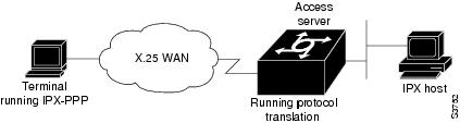
You can enable IPX-PPP on virtual terminals, which permits clients to log in to a virtual terminal on a router, invoke a PPP session at the EXEC prompt to a host, and run IPX to the host.
For example, in Figure 33 the client terminal on the X.25 network logs in to the vty on the access server, which is configured for IPX-PPP. When the user connects to the access server and the EXEC prompt appears, the user issues the PPP command to connect to the IPX host. The virtual terminal is configured to run IPX, so when the PPP session is established from the access server, the terminal can access the IPX host using an IPX application.
Figure 33 IPX-PPP on a Virtual Asynchronous Interface
To enable IPX to run over your PPP sessions on virtual terminal lines, use the following commands beginning in global configuration mode:
|
|
|
|
|---|---|---|
Step 1 |
Router(config)# ipx routing [node] |
Enables IPX routing. |
Step 2 |
Router(config)# interface loopback number |
Creates a loopback interface. |
Step 3 |
|
Enables a virtual IPX network on the loopback interface. |
Step 4 |
|
Enables IPX-PPP on virtual terminal lines by assigning the virtual terminal to the loopback interface configured for IPX. |
1 Every loopback interface must have a unique IPX network number. |
Enabling Dynamic Routing on Virtual Asynchronous Interfaces
To route IP packets using the Interior Gateway Routing Protocol (IGRP), RIP, and OSPF routing protocols on virtual asynchronous interfaces, use the following command in global configuration mode:
|
|
|
|---|---|
Router(config)# vty-async dynamic-routing |
Enables dynamic routing of IP packets on all virtual terminal lines. |
When you make a connection, you must specify the routing keyword on the SLIP or PPP command line.
Note ![]() The vty-async dynamic routing command is similar to the async dynamic routing command, except that the async dynamic routing command is used for physical asynchronous interfaces, and the vty-async dynamic-routing command is used on virtual terminal lines configured for asynchronous protocol functionality.
The vty-async dynamic routing command is similar to the async dynamic routing command, except that the async dynamic routing command is used for physical asynchronous interfaces, and the vty-async dynamic-routing command is used on virtual terminal lines configured for asynchronous protocol functionality.
Enabling TCP/IP Header Compression on Virtual Asynchronous Interfaces
You can compress the headers on TCP/IP packets on virtual asynchronous interfaces to reduce their size and increase performance. This feature only compresses the TCP header, so it has no effect on UDP packets or other protocol headers. The TCP header compression technique, described fully in RFC 1144, is supported on virtual asynchronous interfaces using PPP and SLIP encapsulation. You must enable compression on both ends of the connection.
You can specify outgoing packets to be compressed only if TCP incoming packets on the same vty are compressed. If you do not specify this option, the Cisco IOS software will compress all traffic. The default is no compression. This option is valid for SLIP.
To compress the headers of outgoing TCP packets on virtual asynchronous interfaces, use the following command in global configuration mode:
|
|
|
|---|---|
Router(config)# vty-async header-compression [passive] |
Enables header compression on IP packets on all virtual terminal lines. |
Enabling Keepalive Updates on Virtual Asynchronous Interfaces
Keepalive updates are enabled on all virtual asynchronous interfaces by default. To change the keepalive timer or disable it on virtual asynchronous interfaces, use the following command in global configuration mode:
|
|
|
|---|---|
Router(config)# vty-async keepalive seconds |
Specifies the frequency with which the Cisco IOS software sends keepalive messages to the other end of an asynchronous serial link. |
The default interval is 10 seconds. It is adjustable in 1-second increments from 0 to 32,767 seconds. To turn off keepalive updates, set the value to 0. A connection is declared down after three update intervals have passed without a keepalive packet being received.
Virtual terminal lines are very low bandwidth. When the keepalive timer is adjusted, large packets can delay the smaller keepalive packets long enough to cause the session to disconnect. You might need to experiment to determine the best value.
Setting an MTU on Virtual Asynchronous Interfaces
The maximum transmission unit (MTU) refers to the size of an IP packet. You might want to change to a smaller MTU size for IP packets sent on a virtual asynchronous interface for any of the following reasons:
•![]() The SLIP or PPP application at the other end only supports packets up to a certain size.
The SLIP or PPP application at the other end only supports packets up to a certain size.
•![]() You want to ensure a shorter delay by using smaller packets.
You want to ensure a shorter delay by using smaller packets.
•![]() The host Telnet echoing takes longer than 0.2 seconds.
The host Telnet echoing takes longer than 0.2 seconds.
For example, at 9600 baud a 1500-byte packet takes about 1.5 seconds to transmit. This delay would indicate an MTU size of about 200, as derived from the following equations:
1.5 seconds / 0.2 seconds = 7.5
1500-byte packet / 7.5 = 200-byte packet
To specify the maximum IP packet size, use the following command in interface configuration mode:
|
|
|
|---|---|
|
Specifies the size of the largest IP packet that the virtual asynchronous interface can support. |
The default MTU size is 1500 bytes. Possible values are 64 bytes to 1,000,000 bytes.
The TCP protocol running on the remote device can have a different MTU size than the MTU size configured on your router. Because the Cisco IOS software performs IP fragmentation of packets larger than the specified MTU, do not change the MTU size unless the SLIP or PPP implementation running on the host at the other end of the asynchronous line supports reassembly of IP fragments.
Enabling PPP Authentication on Virtual Asynchronous Interfaces
You can enable Challenge Handshake Authentication Protocol (CHAP) or Password Authentication Protocol (PAP) for authentication of PPP on virtual terminal lines set up for asynchronous protocol features.
Note ![]() Passwords cannot contain spaces or underscores. A user with a password containing spaces or underscores will not be able to log in to a TTY or vty.
Passwords cannot contain spaces or underscores. A user with a password containing spaces or underscores will not be able to log in to a TTY or vty.
Enabling CHAP
Access control using CHAP is available on all virtual asynchronous interfaces configured for PPP encapsulation. The authentication feature reduces the risk of security violations on your router.
When CHAP is enabled, a remote device (such as a PC, workstation, or router) attempting to connect to the local router is requested, or "challenged," to respond.
The challenge contains an ID, a random number, and either the host name of the local router or the name of the user on the remote device. This challenge is sent to the remote device.
The required response has two parts:
•![]() An encrypted version of the ID, a password, and the random number (secreted information)
An encrypted version of the ID, a password, and the random number (secreted information)
•![]() Either the host name of the remote device or the name of the user on the remote device
Either the host name of the remote device or the name of the user on the remote device
When the local router receives the challenge response, it verifies the secreted information by looking up the name given in the response and performing the same encryption operation. The passwords must be identical on the remote device and the local router.
Because this response is sent, the secreted information is never sent, thus preventing other devices from stealing it and gaining illegal access to the system. Without the proper response, the remote device cannot connect to the local router.
CHAP transactions occur only when a link is established. The local router does not request a password during the rest of the session. (The local router can, however, respond to such requests from other devices during a session.)
To use CHAP on virtual asynchronous interfaces for PPP, use the following command in global configuration mode:
|
|
|
|---|---|
Router(config)# vty-async ppp authentication chap |
Enables CHAP on all virtual asynchronous interfaces. |
CHAP is specified in RFC 1334. It is an additional authentication phase of the PPP Link Control Protocol (LCP).
Once you have enabled CHAP, the local router requires a response from the remote devices. If the remote device does not support CHAP, no traffic is passed to that device.
Enabling PAP
Access control using the PAP is available on all virtual asynchronous interfaces configured for PPP encapsulation. The authentication feature reduces the risk of security violations on your router.
To enable PAP, use the following command in interface configuration mode:
|
|
|
|---|---|
|
Enables PAP on all virtual asynchronous interfaces. |
Enabling PPP Authentication via TACACS on Virtual Asynchronous Interfaces
Access control using TACACS is available on all virtual asynchronous interfaces configured for PPP encapsulation. The authentication feature reduces the risk of security violations on your router.
To enable TACACS with either CHAP or PAP, use the following command in global configuration mode:
|
|
|
|---|---|
Router(config)# vty-async ppp use-tacacs |
Enables TACACS on all virtual asynchronous interfaces. |
Maintaining Virtual Interfaces
To maintain virtual interfaces, perform the tasks described in the following sections:
•![]() Monitoring and Maintaining a Virtual Access Interface
Monitoring and Maintaining a Virtual Access Interface
•![]() Displaying a Virtual Asynchronous Interface
Displaying a Virtual Asynchronous Interface
•![]() Troubleshooting Virtual Asynchronous Interfaces
Troubleshooting Virtual Asynchronous Interfaces
Monitoring and Maintaining a Virtual Access Interface
When a virtual interface template is applied to a protocol translation session, a virtual access interface is created dynamically, and is the only way a virtual access interface can be created. However, a virtual access interface can be cleared and displayed.
To display or clear a specific virtual access interface, use any the following commands in EXEC mode:
Displaying a Virtual Asynchronous Interface
To view information about the vty when the configuration of a virtual interface template is cloned to a vty configured as a virtual access interface for two-step protocol translation, use the following command in EXEC mode:
|
|
|
|---|---|
|
Displays statistics about a vty. |
Troubleshooting Virtual Asynchronous Interfaces
The following example shows debug command output for the router redmount. It also shows the output for a specific vty-async interface. The vty-async command configures all virtual terminal lines on a router to support asynchronous protocol features.
Router# show debug
PPP:
PPP protocol negotiation debugging is on
Asynchronous interfaces:
Async interface framing debugging is on
Async interface state changes debugging is on
ROUTER1#
ROUTER1#
Initializing ATCP
VTY-Async3: Set up PPP encapsulation on TTY3
VTY-Async3: Setup PPP framing on TTY3
VTY-Async3: Async protocol mode started for 172.22.164.1
%LINK-3-UPDOWN: Interface VTY-Async3, changed state to up
ppp: sending CONFREQ, type = 2 (CI_ASYNCMAP), value = A0000
ppp: sending CONFREQ, type = 5 (CI_MAGICNUMBER), value = 91B8C7
ppp: sending CONFREQ, type = 2 (CI_ASYNCMAP), value = A0000
ppp: sending CONFREQ, type = 5 (CI_MAGICNUMBER), value = 91B8C7
ROUTER1# debug 0x2
ppp: config ACK received, type = 2 (CI_ASYNCMAP), value = A0000
ppp: config ACK received, type = 5 (CI_MAGICNUMBER), value = 91B8C7
ppp: config ACK received, type = 7 (CI_PCOMPRESSION)
ppp: config ACK received, type = 8 (CI_ACCOMPRESSION)
PPP VTY-Async3: received config for type = 0x1 (MRU) value = 0x5DC acked
PPP VTY-Async3: received config for type = 0x2 (ASYNCMAP) value = 0x0 acked
PPP VTY-Async3: received config for type = 0x7 (PCOMPRESSION) acked
PPP VTY-Async3: received config for type = 0x8 (ACCOMPRESSION) acked
ipcp: sending CONFREQ, type = 3 (CI_ADDRESS), Address = 272.22.213.7
ppp VTY-Async3: ipcp_reqci: rcvd COMPRESSTYPE (rejected) (REJ)
  ppp VTY-Async3: Negotiate IP address: her address 10.1.1.1 (NAK with address 172.22.164.1)
(NAK)
ppp: ipcp_reqci: returning CONFREJ.
PPP VTY-Async3: state = REQSENT fsm_rconfack(0x8021): rcvd id 0x1
ipcp: config ACK received, type = 3 (CI_ADDRESS), Address = 172.21.213.7
  ppp VTY-Async3: Negotiate IP address: her address 10.1.1.1 (NAK with address 172.22.164.1)
(NAK)
ppp: ipcp_reqci: returning CONFNAK.
ppp VTY-Async3: Negotiate IP address: her address 172.22.164.1 (ACK)
ppp: ipcp_reqci: returning CONFACK.
%LINEPROTO-5-UPDOWN: Line protocol on Interface VTY-Async3, changed state to up
Router# show interface vty-async 3
VTY-Async3 is up, line protocol is up
Hardware is Virtual Async Serial
Interface is unnumbered. Using address of Ethernet0 (172.21.213.7)
MTU 1500 bytes, BW 9 Kbit, DLY 100000 usec, rely 255/255, load 1/255
Encapsulation PPP, loopback not set, keepalive set (10 sec)
DTR is pulsed for 0 seconds on reset
lcp state = OPEN
ncp ccp state = NOT NEGOTIATED ncp ipcp state = OPEN
ncp osicp state = NOT NEGOTIATED ncp ipxcp state = NOT NEGOTIATED
ncp xnscp state = NOT NEGOTIATED ncp vinescp state = NOT NEGOTIATED
ncp deccp state = NOT NEGOTIATED ncp bridgecp state = NOT NEGOTIATED
ncp atalkcp state = NOT NEGOTIATED ncp lex state = NOT NEGOTIATED
ncp cdp state = NOT NEGOTIATED
Last input 0:00:01, output 0:00:02, output hang never
Last clearing of "show interface" counters never
Input queue: 1/75/0 (size/max/drops); Total output drops: 0
Output queue: 0/64/0 (size/threshold/drops)
Conversations 0/1 (active/max active)
Reserved Conversations 0/0 (allocated/max allocated)
5 minute input rate 0 bits/sec, 0 packets/sec
5 minute output rate 0 bits/sec, 0 packets/sec
26 packets input, 1122 bytes, 0 no buffer
Received 0 broadcasts, 0 runts, 0 giants
0 input errors, 0 CRC, 0 frame, 0 overrun, 0 ignored, 0 abort
Monitoring Protocol Translation Connections
This section describes how to log significant virtual terminal-asynchronous authentication information, such as the X.121 calling address, CUD, and the IP address assigned to a virtual terminal asynchronous connection. Depending on how you configure the logging information to be displayed, you can direct this authentication information to the console, an internal buffer, or a UNIX syslog server. This authentication information can be used to associate an incoming PAD virtual terminal-asynchronous connection with an IP address.
Note ![]() By default, the Cisco IOS software displays all messages to the console terminal.
By default, the Cisco IOS software displays all messages to the console terminal.
To monitor protocol translation connections, perform the tasks described in the following sections:
•![]() Logging vty-Asynchronous Authentication Information to the Console Terminal
Logging vty-Asynchronous Authentication Information to the Console Terminal
•![]() Logging vty-Asynchronous Authentication Information to a Buffer
Logging vty-Asynchronous Authentication Information to a Buffer
•![]() Logging vty-Asynchronous Authentication Information to a UNIX Syslog Server
Logging vty-Asynchronous Authentication Information to a UNIX Syslog Server
Logging vty-Asynchronous Authentication Information to the Console Terminal
To log significant vty-asynchronous authentication information to the console terminal, use the following command in global configuration mode:
|
|
|
|---|---|
Router(config)# service pt-vty-logging |
Logs significant virtual terminal-asynchronous authentication information. |
Logging vty-Asynchronous Authentication Information to a Buffer
To log significant vty-asynchronous authentication information to a buffer, use the following commands in global configuration mode as needed:
Logging vty-Asynchronous Authentication Information to a UNIX Syslog Server
To log significant vty-asynchronous authentication information to a UNIX syslog server, use the following commands in global configuration mode as needed:
Troubleshooting Protocol Translation
To troubleshoot your protocol translation sessions, use the following show and debug commands:
•![]() debug async
debug async
•![]() debug pad
debug pad
•![]() show arap
show arap
•![]() show async status
show async status
•![]() show interfaces virtual-access
show interfaces virtual-access
•![]() show ip local pool
show ip local pool
•![]() show line
show line
Use these commands in EXEC mode. Refer to the Cisco IOS command references for explanations of command output.
Virtual Template for Protocol Translation Examples
The following sections show examples of configuring tunneling of PPP and SLIP using one-step and two-step protocol translation:
One-Step Examples
The examples in the following sections show how to configure virtual templates and apply them in one-step protocol translation sessions:
•![]() Tunnel PPP Across X.25 Example
Tunnel PPP Across X.25 Example
•![]() Tunnel SLIP Across X.25 Example
Tunnel SLIP Across X.25 Example
•![]() Tunnel PPP Across X.25 and Specifying CHAP and Access List Security Example
Tunnel PPP Across X.25 and Specifying CHAP and Access List Security Example
•![]() Tunnel PPP with Header Compression On Example
Tunnel PPP with Header Compression On Example
•![]() Tunnel IPX-PPP Across X.25 Example
Tunnel IPX-PPP Across X.25 Example
Tunnel PPP Across X.25 Example
The following example shows a virtual interface template that specifies a peer IP address of 172.18.2.131, which is the IP address of the PC in Figure 34. The virtual interface template explicitly specifies PPP encapsulation. The translation is from X.25 to PPP, which enables tunneling of PPP across an X.25 network, as shown in Figure 34.
interface virtual-template 1
ip unnumbered Ethernet0
! Static address of 172.18.2.131 for the PC dialing in to the corporate intranet.
peer default ip address pool group1
! Where the pool name is defined as ip local pool group1 172.18.35.1 172.18.35.5.
encapsulation ppp
! X.121 address of 5555678 is the number the PAD dials to connect through the router.
translate x25 5555678 virtual-template 1
Figure 34 Tunneling PPP Across an X.25 Network
Tunnel SLIP Across X.25 Example
The following example uses SLIP encapsulation instead of the PPP encapsulation on the virtual interface:
interface Virtual-Template5
ip unnumbered Ethernet0
encapsulation slip
peer default ip address pool group1
! Where the pool name is defined as ip local pool group1 172.18.35.11 172.18.35.15.
!
translate x25 5555000 virtual-template 5
Tunnel PPP Across X.25 and Specifying CHAP and Access List Security Example
The following example uses PPP encapsulation on the virtual terminal interface, although it is not explicitly specified. It also uses CHAP authentication and an X.29 access list.
x29 access-list 1 permit ^5555
!
interface Virtual-Template1
ip unnumbered Ethernet0
peer default ip address pool group1
! Where the pool name is defined as ip local pool group1 172.18.35.21 172.18.35.25.
ppp authentication chap
!
translate x25 5555667 virtual-template 1 access-class 1
Tunnel PPP with Header Compression On Example
The following example uses TCP header compression when tunneling PPP across X.25:
interface Virtual-Template1
ip unnumbered Ethernet0
ip tcp header-compression passive
peer default ip address pool group1
! Where the pool name is defined as ip local pool group1 172.18.35.31 172.18.35.35.
!
translate x25 5555676 virtual-template 1
Tunnel IPX-PPP Across X.25 Example
The following example shows how to tunnel IPX-PPP across the X.25 network. It creates an internal IPX network number on a loopback interface, then assigns that loopback interface to the virtual interface template.
ipx routing 0000.0c07.b509
!
interface loopback0
ipx network 544
ipx sap-interval 2000
!
interface Virtual-Template1
ip unnumbered Ethernet0
ipx ppp-client Loopback0
peer default ip address pool group1
! Where the pool name is defined as ip local pool group1 172.18.35.41 172.18.35.45.
!
translate x25 5555766 virtual-template 1
Two-Step Examples
The examples in the following sections show how to create and configure virtual interface templates and apply them in two-step protocol translation sessions:
•![]() Two-Step Tunneling of PPP with Dynamic Routing and Header Compression Example
Two-Step Tunneling of PPP with Dynamic Routing and Header Compression Example
•![]() Two-Step Tunneling of PPP with Dynamic Routing, TACACS, and CHAP Example
Two-Step Tunneling of PPP with Dynamic Routing, TACACS, and CHAP Example
Two-Step Tunneling of PPP with Dynamic Routing and Header Compression Example
The following example uses the default PPP encapsulation on the virtual template. The example does not specify a peer default IP address because it is using two-step translation.
vty-async
vty-async virtual-template 1
vty-async dynamic-routing
vty-async header-compression
!
interface Virtual-Template1
ip unnumbered Ethernet0
no peer default ip address
After users connect to the router (in this example, named waffler), they invoke the ppp command to complete the two-step connection:
Router> ppp /routing /compressed 172.16.2.31
Entering PPP routing mode.
Async interface address is unnumbered (Ethernet0)
Your IP address is 172.16.2.31. MTU is 1500 bytes
Two-Step Tunneling of PPP with Dynamic Routing, TACACS, and CHAP Example
The virtual template interface in the following example uses the default encapsulation of PPP and applies CHAP authentication with TACACS+:
aaa authentication ppp default tacacs+
!
vty-async
vty-async dynamic-routing
vty-async virtual-template 1
!
interface Ethernet0
ip address 10.11.12.2 255.255.255.0
!
interface Virtual-Template1
ip unnumbered Ethernet0
no peer default ip address
ppp authentication chap
Protocol Translation Application Examples
This section provides protocol translation examples for the following scenarios:
•![]() Central Site Protocol Translation Example
Central Site Protocol Translation Example
•![]() Decreasing the Number of Translation Sessions Example
Decreasing the Number of Translation Sessions Example
•![]() Increasing the Number of Translation Sessions Example
Increasing the Number of Translation Sessions Example
•![]() LAT-to-LAT over an IP WAN Example
LAT-to-LAT over an IP WAN Example
•![]() LAT-to-LAT over Frame Relay or SMDS Example
LAT-to-LAT over Frame Relay or SMDS Example
•![]() LAT-to-LAT Translation over a WAN Example
LAT-to-LAT Translation over a WAN Example
•![]() LAT-to-LAT over an X.25 Translation Example
LAT-to-LAT over an X.25 Translation Example
•![]() LAT-to-TCP Translation over a WAN Example
LAT-to-TCP Translation over a WAN Example
•![]() LAT-to-X.25 Host Configuration Example
LAT-to-X.25 Host Configuration Example
•![]() Local LAT-to-TCP Translation Example
Local LAT-to-TCP Translation Example
•![]() Local LAT-to-TCP Configuration Example
Local LAT-to-TCP Configuration Example
•![]() Standalone LAT-to-TCP Translation Example
Standalone LAT-to-TCP Translation Example
•![]() Tunneling SLIP Inside TCP Example
Tunneling SLIP Inside TCP Example
•![]() Tunneling PPP over X.25 Example
Tunneling PPP over X.25 Example
•![]() X.25 to L2F PPP Tunneling Example
X.25 to L2F PPP Tunneling Example
•![]() Assigning Addresses Dynamically for PPP Example
Assigning Addresses Dynamically for PPP Example
•![]() Local IP Address Pool Example
Local IP Address Pool Example
•![]() X.25 PAD-to-LAT Configuration Example
X.25 PAD-to-LAT Configuration Example
•![]() X.25 PAD-to-TCP Configuration Example
X.25 PAD-to-TCP Configuration Example
Note ![]() In the application illustrations throughout the remainder of this chapter, source and destination device icons used to illustrate the flow of translated information are shown with black type in outlined shapes. Other elements in the environment are shown with reverse type on solid black shapes.
In the application illustrations throughout the remainder of this chapter, source and destination device icons used to illustrate the flow of translated information are shown with black type in outlined shapes. Other elements in the environment are shown with reverse type on solid black shapes.
Basic Configuration Example
The following examples illustrate the basic global configuration commands and interface configuration commands for setting up Router-A (connected to Network A) and Router-B (connected to Network B), as illustrated in Figure 35. Refer to the chapter "Configuring Dial-In Terminal Services," for more information about LAT. For information on configuring X.25, refer to the Cisco IOS Wide-Area Networking Configuration Guide, Release 12.2.
Figure 35 Routers with Protocol Translation
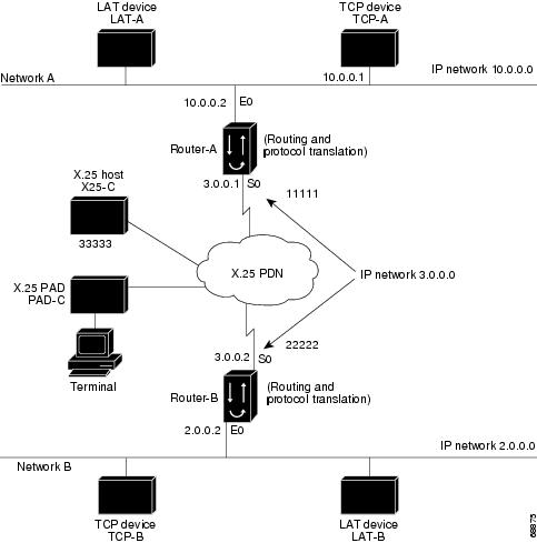
Note ![]() The examples that follow focus on creating configurations that support one-step protocol translation. These connections can also be made using the two-step protocol translation method.
The examples that follow focus on creating configurations that support one-step protocol translation. These connections can also be made using the two-step protocol translation method.
Configuration for Router-A
The following partial configuration for Router-A outlines a baseline configuration for Ethernet and serial interfaces on a router and configures support for IP, LAT, and X.25:
interface ethernet 0
ip address 10.0.0.2 255.255.0.0
!
! Enable LAT on interface.
lat enabled
!
interface serial 0
encapsulation X.25
x25 address 11111
!
! The following parameters may depend on your network.
x25 facility packetsize 512 512
x25 facility windowsize 7 7
!
! IP address and MAP command needed only if routing IP.
ip address 10.3.0.1 255.255.0.0
x25 map ip 10.3.0.2 22222 broadcast
!
! Set up IP routing.
router igrp 100
network 10.0.0.0
network 10.3.0.0
!
! Advertise as available for connections via LAT.
! Use this name (router-A) if connecting via 2-step method
! (for connecting directly to a specific router).
lat service router-A enable
!
! Set up some IP host names/addresses.
ip host router-A 10.0.0.2 10.3.0.1
ip host TCP-A 10.0.0.1
ip host TCP-B 10.2.0.1
ip host router-B 10.3.0.2 10.2.0.2
Configuration for Router-B
The following partial configuration for Router-B outlines a baseline configuration for Ethernet and serial interfaces on a router and configures support for IP, LAT, and X.25:
interface ethernet 0
ip address 10.2.0.2 255.255.0.0
!
! Enable LAT on interface.
lat enabled
!
interface serial 0
encapsulation X.25
x25 address 22222
! The following parameters may depend on your network.
x25 facility packetsize 512 512
x25 facility windowsize 7 7
!
! IP address and MAP command needed only if routing IP.
ip address 10.3.0.2 255.255.0.0
x25 map ip 10.3.0.1 11111 broadcast
!
! Set up IP routing.
router igrp 100
network 10.2.0.0
network 10.3.0.0
!
! Advertise as available for connections via LAT.
! Use this name (router-B) if connecting via 2-step method
! (for connecting directly to a specific router).
lat service router-B enable
!
! Set up some IP host names/addresses.
ip host router-A 10.3.0.1 10.0.0.2
ip host TCP-A 10.0.0.1
ip host TCP-B 10.2.0.1
ip host router-B 10.2.0.2 10.3.0.2
Note ![]() You can specify IP host names used to identify specific hosts by explicitly using the ip host global configuration command or by using Domain Name System (DNS) facilities.
You can specify IP host names used to identify specific hosts by explicitly using the ip host global configuration command or by using Domain Name System (DNS) facilities.
Central Site Protocol Translation Example
To support central site protocol translation, a router with an image that supports protocol translation is directly connected back-to-back to another router (see Figure 36). This second device acts as an X.25 switch by sending X.25 packets to Router-B while concurrently routing and bridging other protocols.
Figure 36 Central Site Protocol Translation Example

The following example shows how to configure a router to support translating protocols over an X.25 network among multiple sites. Router-C is configured to act as an X.25 switch to send X.25 packets to Router-A while concurrently routing and bridging other protocols.
The following example also shows how to use the translate global configuration command to translate LAT and TCP over X.25 WAN media. In this configuration, Router-A can translate LAT or TCP traffic into X.25 packets for transmission over an X.25 PDN network. Packets are then translated back to LAT or TCP on the other side of the WAN.
interface ethernet 0
ip address 10.0.0.2 255.255.0.0
!
! Enable LAT on interface if concurrently routing (8.3 feature).
lat enable
!
interface serial 0
encapsulation X.25
! Note that this is subaddress 3 of 11111.
x25 address 111113
! The following parameters may depend on your network.
x25 facility packetsize 512 512
x25 facility windowsize 7 7
no ip address
! Translate Configuration for router-A.
!
no ip routing
! Note subaddress 03 of address 111113.
translate x25 11111303 tcp tcpdevice
translate lat TCP-B x25 3333301
translate lat lat-device tcp tcp-device
! etc...any translate commands needed by application.
Decreasing the Number of Translation Sessions Example
The following example sets the number of protocol translation sessions to 10, whether routing is turned on or off:
no line vty 10
Increasing the Number of Translation Sessions Example
The following example sets the number of protocol translation sessions to 120, whether routing is turned on or off:
line vty 119
LAT-to-LAT over an IP WAN Example
The Cisco IOS software can be used to connect LAT devices over a WAN backbone that only allows routable protocols (see Figure 37). This configuration exists when LAT networks are either isolated or on their own internetwork.
With the protocol translation, LAT traffic can be translated to TCP and then routed on the WAN as TCP traffic. The LAT connections stay local between the LAT device and the router running the protocol translation option. Thus, connections are not susceptible to delays on the WAN. This capability reduces the amount of traffic on the WAN because only the data from specific LAT sessions is forwarded on the WAN rather than all the LAT protocol status information packets.
Figure 37 LAT-to-LAT over an IP WAN
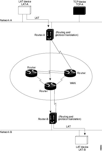
The following example illustrates how to use the translate global configuration command to translate from LAT to LAT when an IP WAN is used. In this configuration, Router-B with the protocol translation option routes encapsulated packets translated from LAT to TCP over the WAN. Router-A translates packets back to LAT on the other side of the WAN. Example translation configurations for both Router-A and Router-B are shown, but these examples do not include configuration information for devices in the WAN.
The following examples are essentially the same configurations for protocol translation as those in the following Frame Relay example:
! Translate LAT to TCP/Telnet for Router-A, which is on Network A.
translate lat DISTANT-LAT tcp Router-A
! Translate TCP to LAT for Router-B, which is on Network B.
translate tcp Router-B lat LAT-B
Note ![]() You can use the same name (for example, LAT-B) in the translate command for both Router-A and Router-B because each router operates independently. However, this symmetry is not required. The key is the common IP name in both translate commands.
You can use the same name (for example, LAT-B) in the translate command for both Router-A and Router-B because each router operates independently. However, this symmetry is not required. The key is the common IP name in both translate commands.
LAT-to-LAT over Frame Relay or SMDS Example
To transport LAT traffic over a Frame Relay or an Switched Multimegabit Data Service (SMDS) network, LAT must first be translated to TCP. The TCP traffic is routed over the Frame Relay network and then translated back to LAT on Router-B on Network B (see Figure 38).
Note ![]() The interface configurations for a Frame Relay or an SMDS implementation differ from the specifications shown earlier in this chapter. For more information about configuring Frame Relay and SMDS, refer to the Cisco IOS Wide-Area Networking Configuration Guide, Release 12.2.
The interface configurations for a Frame Relay or an SMDS implementation differ from the specifications shown earlier in this chapter. For more information about configuring Frame Relay and SMDS, refer to the Cisco IOS Wide-Area Networking Configuration Guide, Release 12.2.
Figure 38 LAT-to-LAT over Frame Relay or SMDS

The following example illustrates how to use the translate global configuration command to translate from LAT to LAT when the WAN uses Frame Relay or SMDS. In this configuration, the Cisco IOS software routes encapsulated packets translated from LAT to TCP over the Frame Relay or SMDS network. Packets are then translated back to LAT on the other side of the Frame Relay or SMDS network.
! Translate LAT to TCP/Telnet on router-A, which is on Network A.
translate lat DISTANT-LAT tcp router-A
! Translate TCP to LAT on router-B, which is on Network B.
translate tcp router-B lat LAT-B
Note ![]() You can use the same name (for example, LAT-B) in the translate command for both Router-A and Router-B because each router operates independently. However, this symmetry is not required. The key is the common IP name used in both translate commands.
You can use the same name (for example, LAT-B) in the translate command for both Router-A and Router-B because each router operates independently. However, this symmetry is not required. The key is the common IP name used in both translate commands.
LAT-to-LAT Translation over a WAN Example
In Figure 39, LAT can be transported to a remote LAT device by translating the packets to TCP format and using Telnet to send them across the WAN. The configuration files for the routers named Router-A and Router-B follow the figure. The logical name CS-B1 is the name given to device CS-B.
Figure 39 LAT-to-LAT Translation over a WAN
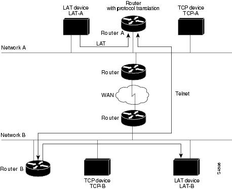
Configuration for Router-A
interface ethernet 0
ip address 172.18.32.16 255.255.0.0
!
! Enable LAT on this interface.
lat enabled
!
translate lat distant-LAT tcp TS-B1
Configuration for Router-B
interface ethernet 0
ip address 172.18.38.42 255.255.0.0
!
! Enable LAT on this interface.
lat enabled
!
translate lat TS-B1 lat LAT-B
LAT-to-LAT over an X.25 Translation Example
Protocol translation provides transparent connectivity between LAT devices on different networks via an X.25 PDN. In Figure 40, which illustrates this application, the LAT device on Network A (LAT-A) first makes a virtual connection to the router named Router-A on Network A using the LAT protocol. Router-A then translates the LAT packets into X.25 packets and sends them through the X.25 network to Router-B on Network B. Router-B translates the X.25 packets back to LAT packets and establishes a virtual connection to the LAT device on Network B (LAT-B). These handoffs are handled transparently when the Cisco IOS software is configured for one-step protocol translation.
Figure 40 LAT-to-LAT via an X.25 PDN
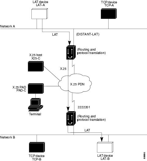
The following example shows how to use the translate global configuration command to translate from LAT to X.25 and from X.25 back to LAT to allow connection service to a LAT device on Network B from a LAT device on Network A. This example requires two separate configurations, one for each LAT device.
! Translate LAT to X.25 on router-A, which is on Network A.
translate lat DISTANT-LAT x25 2222201
! Translate X.25 to LAT on router-B, which is on Network B.
translate x25 2222201 lat LAT-B
In the first translate command, DISTANT-LAT defines a LAT service name for Router-A. When a user on device LAT-A attempts to connect to LAT-B, the target specified in the connect command is DISTANT-LAT.
In the translate command for Router-B, the name of the LAT service on the target host (LAT-B) is LAT-B. Router-B translates the incoming X.25 packets from 2222201 to LAT and then transparently relays these packets to LAT-B.
The following example shows a connection request. When the user enters this command, a connection attempt from LAT-A on Network A to TCP-B on Network B is attempted.
Router> connect DISTANT-LAT
To configure Router-B to send information back from LAT-B to LAT-A, use commands symmetrical to the prior configuration (this path is not shown in Figure 40):
! Translate LAT to X.25 on router-B, which is on Network B.
translate lat FAR-LAT x25 1111103
! Translate X.25 to LAT on router-A, which is on Network A.
translate x25 1111103 lat LAT-A
Note ![]() You can use the same name (for example, LAT-B) in the translate command for both Router-A and Router-B because each router with the protocol translation option operates independently. However, this symmetry is not required. The key is the common X.121 address used in both translate commands. If you prefer to have unique service names, set the names in each router to be the same.
You can use the same name (for example, LAT-B) in the translate command for both Router-A and Router-B because each router with the protocol translation option operates independently. However, this symmetry is not required. The key is the common X.121 address used in both translate commands. If you prefer to have unique service names, set the names in each router to be the same.
LAT-to-TCP Translation over a WAN Example
Figure 41 shows a configuration that allows translation of LAT to TCP and transmission across an IP-based WAN. The configuration file for the access server identified as A follows the figure. The logical LAT service name distant-TCP is the name given to device TCP-B.
Figure 41 LAT-to-TCP Translation over a WAN
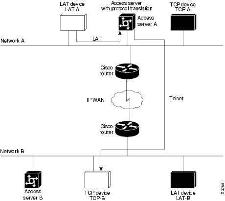
Configuration for Access Server A
interface ethernet 0
ip address 172.18.38.42 255.255.0.0
!
! Enable LAT on this interface.
lat enabled
!
translate lat distant-TCP tcp TCP-B
LAT-to-TCP over X.25 Example
You can use protocol translation to provide transparent connectivity between LAT and TCP devices on different networks via an X.25 PDN. In Figure 42, which illustrates this application, the LAT device on Network A is communicating with the TCP device on Network B. There are two ways to provide this connectivity: The LAT traffic from Network A can be translated into either X.25 packets, or TCP/IP packets can be sent out on the X.25 PDN.
If the traffic is translated from LAT directly into X.25 frames by Router-A, Router-B on Network B translates incoming packets intended for device TCP-B into TCP. If Router-A converts LAT to TCP, the TCP traffic is being encapsulated in X.25 and sent on the X.25 network. Router-B on Network B strips off the encapsulation and routes the TCP packet. In this case, protocol translation is not needed on Router-B.
If the traffic is translated to TCP by Router-A, the packets are encapsulated within X.25 frames. In general, translating the traffic directly to X.25 is more efficient in this application because no encapsulation is necessary. X.25 packets have only 5 bytes of header information, and TCP over X.25 has 45 bytes of header information.
Figure 42 LAT-to-TCP via X.25
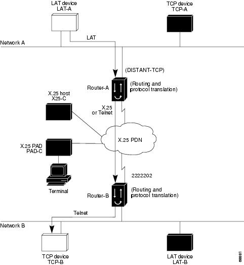
The following example shows how to use the translate global configuration command to translate from LAT to X.25 (on Router-A) and from X.25 to TCP (on Router-B), thus allowing connection service to a TCP device on Network B (TCP-B) from a LAT device on Network A (LAT-A). You must configure Router-A and Router-B separately.
! Translate LAT to X.25 on router-A, which is on Network A.
translate lat DISTANT-TCP x25 2222202
! Translate X.25 to TCP on router-B, which is on Network B.
translate x25 2222202 tcp TCP-B
In the translate command for Router-A, DISTANT-TCP defines a LAT service name for Router-A. When a user on device LAT-A attempts to connect to LAT-B, the target specified in the connect command is DISTANT-TCP.
In the translate command for Router-B, the TCP service on the target host is TCP-B. Router-B translates the incoming X.25 packets from 2222202 to TCP packets and transparently relays these packets to TCP-B.
The following example shows a connection request. When the user enters this command, a connection attempt from LAT-A on Network A to LAT-B on Network B is attempted.
local> connect DISTANT-TCP
Note ![]() You can use the same name (for example, TCP-B) in the translate command for both Router-A and Router-B because each router operates independently. However, this symmetry is not required. The key is the common X.121 address used in both translate commands. If you prefer to have unique service names, set the names in each router to be the same.
You can use the same name (for example, TCP-B) in the translate command for both Router-A and Router-B because each router operates independently. However, this symmetry is not required. The key is the common X.121 address used in both translate commands. If you prefer to have unique service names, set the names in each router to be the same.
LAT-to-X.25 Host Configuration Example
Figure 43 shows a protocol translation configuration that permits LAT devices to communicate with X.25 hosts through an X.25 PDN. In the application illustrated in Figure 43, LAT-A is a LAT device that is communicating with X25-C, an X.25 host. The LAT traffic from LAT-A is translated to X.25.
Figure 43 LAT-to-X.25 Host Translation
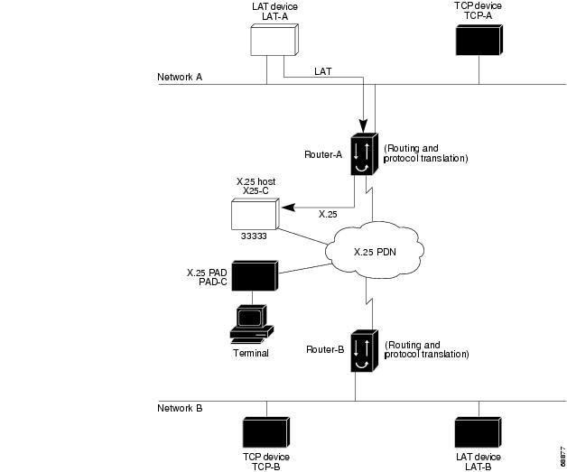
The following example shows how to use the translate global configuration command to translate from LAT to X.25. It is applied to Router-A. This example sets up reverse charging for connections, which causes the router with the protocol translation option to instruct the PDN to charge the destination for the connection. It is essentially a collect call. The reversal of charges must be prearranged with the PDN and destination location (on an administrative basis), or the call will not be accepted.
! Translate LAT to X.25 host, with reverse charging.
translate lat X25-C x25 33333 reverse
!
! Specify optional X.25 hostname.
x25 host X25-C 33333
Local LAT-to-TCP Translation Example
Figure 44 shows a simple LAT-to-TCP translation across an Ethernet network. Its Cisco IOS configuration file follows the figure. The name TCP-A is the logical name given to the device TCP-A.
Figure 44 Local LAT-to-TCP Translation

Configuration for the Access Server
interface ethernet 0
ip address 172.18.38.42 255.255.0.0
!
! Enable LAT on this interface.
lat enabled
!
translate lat TCPA tcp TCP-A
Local LAT-to-TCP Configuration Example
The Cisco IOS software running protocol translation can translate between LAT and Telnet traffic to allow communication among resources in these protocol environments. In Figure 45, the LAT device on Network A (LAT-A) is shown connecting to a device running Telnet (TCP-A).
The commands in this example are only part of the complete configuration file for an individual device.
Figure 45 Local LAT-to-TCP Translation
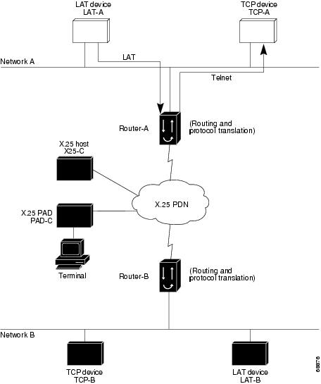
The following example configures Router-A to translate from LAT to TCP:
! Translate LAT connections to TCP for connectivity to TCP-A.
translate lat TCP-A tcp TCP-A
! Optional additional commands.
lat service TCP-A ident Protocol Translation to TCP-A
In the last command, the text string "Protocol Translation to TCP-A" is an identification string for the LAT service named TCP-A. This string is sent to other routers on the local network.
Standalone LAT-to-TCP Translation Example
If you need a large number of local LAT-to-TCP translation sessions, you can set up the router named Router-A to use only an Ethernet port, as the example following Figure 46 indicates. This application allows 100 concurrent translation sessions. In the applications shown in Figure 46, any other router that supports protocol translation can be used to interconnect network segments performing bridging or routing.
Figure 46 Router Functioning as a Standalone Protocol Translator

Configuration for Router-A
! Translation Configuration for Router-A only.
!
interface ethernet 0
ip address 10.0.0.2 255.255.0.0
!
! Enable LAT on this interface.
lat enabled
!
interface serial 0
shutdown
no ip routing
default-gateway 10.0.0.100
!
translate lat TCP-A tcp TCP-A
translate lat TCP-B tcp TCP-B
translate tcp LAT-A lat lat-z
! etc...translate commands as required.
Tunneling SLIP Inside TCP Example
Protocol translation enables you to tunnel from TCP to SLIP to allow communication among resources in these protocol environments. In Figure 47, the PC running SLIP is connecting to a TCP/IP network and making a connection with the device IP host. The example following Figure 47 enables routing and turns on header compression.
Figure 47 Tunneling SLIP Inside TCP
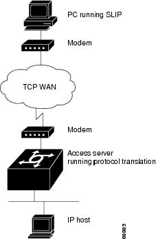
The configuration tunnels SLIP inside of TCP packets from the SLIP client with IP address 10.2.0.5 to the router. It then establishes a protocol translation session to the IP host. Routing and header compression are enabled for the SLIP session.
translate tcp 10.0.0.1 slip 10.2.0.5 routing header-compression passive
The device IP host on a different network attached to the router can be accessed by the SLIP client because routing has been enabled on the interface in the router where the SLIP session is established.
This example is incomplete. The commands in this example are only part of the complete configuration file for an individual router.
Tunneling PPP over X.25 Example
Cisco IOS software can tunnel PPP traffic across an X.25 WAN to allow communication among resources in these protocol environments. In Figure 48, the PC establishes a dialup PPP session through an X.25 network using CHAP authentication.
Figure 48 Tunneling PPP in X.25
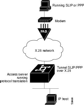
The following configuration tunnels PPP over X.25 from the PPP client to the virtual asynchronous interface with IP address 10.0.0.4. Routing and CHAP authentication are enabled for the PPP session. The X.121 address of the X.25 host is 31370054065. An X.29 profile script named x25-ppp is created using the following X.3 PAD parameters:
1:0, 2:0, 3:2, 4:1, 5:0, 6:0, 7:21, 8:0, 9:0, 10:0, 11:14, 12:0, 13:0, 14:0, 15:0, 16:127, 17:24, 18:18, 19:0, 20:0, 21:0, 22:0
For more information about X.3 PAD parameters, refer to the appendix "X.3 PAD Parameters" at the end of this publication. If you were performing a two-step connection, you would specify these X.3 PAD parameters using the pad [/profile name] command.
With the router connected to the IP host, the PC running PPP can now communicate with the IP host.
Router# configure terminal
Router(config)# X29 profile x25-ppp 1:0  2:0  3:2  4:1  5:0  6:0  7:21  8:0  9:0 10:0
11:14  12:0  13:0  14:0  15:0  16:127  17:24 18:18
Router(config)# translate x25 31370054065 profile x25-ppp ppp 10.0.0.4 routing
authentication chap
This example is incomplete. The commands in this example are only a part of the complete configuration file for an individual router.
X.25 to L2F PPP Tunneling Example
Protocol translation permits remote PPP users to connect to an X.25 PAD to communicate with IP network users via an L2F tunnel. (See Figure 49.)
Figure 49 L2F PPP Tunneling in X.25
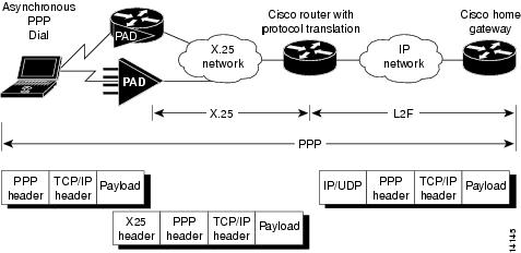
The client application generates TCP/IP packets, which the PPP driver on the remote PC sends to the PAD. The PAD can either be an existing X.25/X.3/X.28/X.29-compliant PAD or a Cisco router with X.25 and PAD capability. The PAD receives the PPP/TCP/IP packets and sends them as X.25/PPP/TCP/IP packets to the X.25 network.
The Cisco router receives the packets and uses the protocol translation code to strip off the X.25 header. The router, using virtual templates, configures VPDN. VPDN invokes L2F tunneling and the virtual access interface via protocol translation, enables PPP to tunnel to the far home gateway and be terminated. At this point, the PC user can use Telnet, File Transfer Protocol (FTP), or similar file transfer utilities. The following is a partial example:
Router# virtual-temp 1
Router# encap ppp
Router# authentication chap
Router# trans x25 1234 virtual-temp 1
The following example shows a VPDN over a protocol translation virtual terminal-asynchronous connection over X.25 WAN. The client username is pc-user@cisco.com, the network access server is shadow (a Cisco router with the protocol translation option), and the home gateway is enkidu. The domain is cisco.com. The configuration for network access server shadow is as follows:
! VPDN NAS and Home Gateway passwords
username shadow password 7 013C142F520F
username enkidu-gw password 7 022916700202
vpdn enable
! VPDN outgoing to Home Gateway
vpdn outgoing cisco.com shadow ip 10.4.4.41
!
interface Virtual-Template1
ip unnumbered Ethernet0
no ip mroute-cache
ppp authentication chap
!
interface Serial0
description connects to enkidu s 0
encapsulation x25 dce
x25 address 2194440
clockrate 2000000
!
translate x25 21944405 virtual-template 1
!
The configuration for home gateway enkidu-gw is as follows:
! VPDN NAS and Home Gateway passwords
username shadow-nas password 7 143800200500
username enkidu-gw password 7 132A05390208
!
! The client user name and password
username pc-user@cisco.com password 7 032B49200F0B
!
vpdn enable
! VPDN incoming from Shadow to this Home Gateway
vpdn incoming shadow enkidu-gw virtual-template 1
!
Assigning Addresses Dynamically for PPP Example
The following example shows how to configure the Cisco IOS software to assign an IP address dynamically to a PPP client using the one-step protocol translation facility:
! Enable DHCP proxy-client status on the router.
ip address-pool dhcp-proxy-client
! Specify rockjaw as the DHCP server on the network.
ip dhcp-server rockjaw
translate x25 5467835 ppp ip-pool keepalive 0
Local IP Address Pool Example
The following example shows how to select the IP pooling mechanism and how to create a pool of local IP addresses that are used when a client dials in on an asynchronous line. The address pool is named group1 and consists of interfaces 0 through 5.
! Tell the server to use a local pool.
ip address-pool local
! Define the range of ip addresses on the local pool.
ip local pool group1 172.18.35.1 192.168.35.5
translate x25 5467835 ppp ip-pool scope-name group1
X.29 Access List Example
The following example shows how to create an X.29 access list. Incoming permit conditions are set for all IP hosts and LAT nodes that have specific characters in their names. All X.25 connections to a printer are denied. Outgoing connections are restricted.
! Permit all IP hosts and LAT nodes beginning with "VMS".
! Deny X.25 connections to the printer on line 5.
!
access-list 1 permit 0.0.0.0 255.255.255.255
lat access-list 1 permit ^VMS.*
x29 access-list 1 deny .*
!
line vty 5
access-class 1 in
!
! Permit outgoing connections for other lines.
!
! Permit IP access with the network 172.16.
access-list 2 permit 172.16.0.0 0.0.255.255
!
! Permit LAT access to the prasad/gopala complexes.
lat access-list 2 permit ^prasad$
lat access-list 2 permit ^gopala$
!
! Permit X.25 connections to Infonet hosts only.
x29 access-list 2 permit ^31370
!
line vty 0 16
access-class 2 out
!
translate tcp 172.16.1.26 x25 5551234 access-class 2
X.3 Profile Example
The following profile script turns local edit mode on when the connection is made and establishes local echo and line termination upon receipt of a Return character. The name linemode is used with the translate command to effect use of this script.
x29 profile linemode 2:1 3:2 15:1
translate tcp 172.16.1.26 x25 55551234 profile linemode
The X.3 PAD parameters are described in the "X.3 PAD Parameters" appendix at the end of this publication.
X.25 PAD-to-LAT Configuration Example
The following examples shows a protocol translation configuration that permits terminals connected to X.25 PADs to communicate with LAT devices on a remote LAN. (See Figure 50.) X.25 PAD terminals make a call using an X.121 address, which is translated to a LAT node. To the PAD terminal user, the connection appears to be a direct connection to a host on the X.25 PDN. The Cisco IOS software also supports X.29 access lists, which allow you to restrict LAN resources (LAT or TCP) available to the PAD user.
Figure 50 X.25 PAD-to-LAT Translation

The following example shows how to use the translate global configuration command to translate from an X.25 PAD to a LAT device on Network A. It is applied to Router-A. The configuration example includes an access list that limits remote LAT access through Router-A to connections from PAD-C.
! Define X25 access list to only allow pad-c.
x29 access-list 1 permit ^44444
x29 access-list 1 deny .*
!
! Set up translation.
translate x25 1111101 lat LAT-A access-class 1
This configuration example typifies the use of access lists in the Cisco IOS software. The first two lines define the scope of access-list 1. The first line specifies that access list 1 will permit all calls from X.121 address 44444. The caret symbol (^) specifies that the first number 4 is the beginning of the address number. Refer to the appendix "Regular Expressions" at the end of this publication for details concerning the use of special characters in defining X.121 addresses. The second line of the definition explicitly denies calls from any other number.
This access list is then applied to all incoming traffic on the serial port for Router-A (X.121 address 1111101) with the third configuration line in the example. However, it applies only to the translate command at the end of this example. This translate command specifies that incoming X.25 packets on the serial line (with address 1111101) are translated to LAT and sent to LAT-A if they pass the restrictions of the access list.
If you define multiple X.25 translate commands, each must contain a unique X.121 address. Also, the International Telecommunication Union Telecommunication Standardization Sector (ITU-T) protocol that transfers packets must match the X.121 addresses. This requirement is specified in the protocol identification field of CUD. This field specifies whether a packet is routed, translated, or handled as a virtual terminal connection.
Note ![]() The X.121 address 1111101 used in this example can be a subaddress of the address 11111 originally assigned to this serial port on Router-A at the beginning of the configuration example section. However, making this assignment is not a requirement. The number to use in the translate command is negotiated (administratively) between your network management personnel and the PDN service provider. The X.121 address in the translate command represents the X.121 address of the calling device. That number may or may not be the number (or a subaddress of the number) administratively assigned to the router with the protocol translation option. You and the PDN must agree on a number to be used, because it is possible that the PDN can be configured to place calls that are intended for a destination on a given line that does not match the number assigned by you in the configuration file. Refer to the 1984 CCITT Red Book specifications for more information concerning X.121 addresses.
The X.121 address 1111101 used in this example can be a subaddress of the address 11111 originally assigned to this serial port on Router-A at the beginning of the configuration example section. However, making this assignment is not a requirement. The number to use in the translate command is negotiated (administratively) between your network management personnel and the PDN service provider. The X.121 address in the translate command represents the X.121 address of the calling device. That number may or may not be the number (or a subaddress of the number) administratively assigned to the router with the protocol translation option. You and the PDN must agree on a number to be used, because it is possible that the PDN can be configured to place calls that are intended for a destination on a given line that does not match the number assigned by you in the configuration file. Refer to the 1984 CCITT Red Book specifications for more information concerning X.121 addresses.
X.25 PAD-to-TCP Configuration Example
Making a translated connection from an X.25 PAD to a TCP device is analogous to the preceding X.25 PAD-to-LAT example. (See Figure 51.) Instead of translating to LAT, the configuration for Router-A includes a statement to translate to TCP (Telnet). Note that a router with the protocol translation software option can include statements supporting both translations (X.25 PAD to LAT and X.25 PAD to TCP). Different users on the same PAD can communicate with X.25, LAT, or TCP devices.
Figure 51 X.25 PAD-to-TCP Translation

The following example shows how to use the translate global configuration command to translate from an X.25 PAD to a TCP device on Network A. It is applied to Router-A.
! Set up translation.
translate x25 2222 tcp TCP-A
Protocol Translation Session Examples
The examples in the following sections show how to make connections for protocol translation using the one-step and two-step methods:
•![]() One-Step Method for TCP-to-X.25 Host Connections Example
One-Step Method for TCP-to-X.25 Host Connections Example
•![]() Using the Two-Step Method for TCP-to-PAD Connections Example
Using the Two-Step Method for TCP-to-PAD Connections Example
•![]() Two-Step Protocol Translation for TCP-to-PAD Connections Example
Two-Step Protocol Translation for TCP-to-PAD Connections Example
•![]() Changing Parameters and Settings Dynamically Example
Changing Parameters and Settings Dynamically Example
•![]() Monitoring Protocol Translation Connections Example
Monitoring Protocol Translation Connections Example
•![]() Two-Step Protocol Translation for Virtual Terminal Asynchronous Interfaces Example
Two-Step Protocol Translation for Virtual Terminal Asynchronous Interfaces Example
One-Step Method for TCP-to-X.25 Host Connections Example
This sample session demonstrates one-step protocol translation featuring a UNIX workstation user making a connection to a remote X.25 host named host1 over an X.25 PDN. The router automatically converts the Telnet connection request to an X.25 connection request and sends the request as specified in the system configuration.
A connection is established when you enter the telnet EXEC command at the UNIX workstation system prompt, as follows:
unix% telnet host1
Note ![]() This example implicitly assumes that the name host1 is known to the UNIX host (obtained via DNS, IEN116, or a static table) and is mapped to the IP address used in a translate command.
This example implicitly assumes that the name host1 is known to the UNIX host (obtained via DNS, IEN116, or a static table) and is mapped to the IP address used in a translate command.
The router accepts the Telnet connection and immediately forms an outgoing connection with remote host1 as defined in a translate command.
Next, host1 sets several X.3 parameters, including local echo. Because the Telnet connection is already set to local echo (at the UNIX host), no changes are made on the TCP connection.
The host1 connection prompts for a user name, then host1 sets the X.3 parameters to cause remote echo (the same process as setting X.3 PAD parameter 2:0), and prompts for a password. The Cisco IOS software converts this request to a Telnet option request on the UNIX host, which then stops the local echo mode.
At this point, the user is connected to the PAD application and the application will set the X.3 PAD parameters (although they can always be overridden by the user). When finished with the connection, the user escapes back to the host connection, then enters the appropriate command to close the connection.
The host named host1 immediately closes the X.25 connection. The Cisco IOS software then drops the TCP connection, leaving the user back at the UNIX system prompt.
Using the Two-Step Method for TCP-to-PAD Connections Example
To use the two-step method for making connections, perform the following steps:
Step 1 ![]() Connect directly from a terminal or workstation to a router.
Connect directly from a terminal or workstation to a router.
For example, you might make the following connection requests at a UNIX workstation as a first step to logging in to the database named Information Place on an X.25 PDN:
unix% telnet orion
If the router named orion is accessible, it returns a login message and you enter your login name and password.
Step 2 ![]() Connect from the router to Information Place, which is on an X.25 host. You connect to an X.25 host using the pad EXEC command followed by the service address:
Connect from the router to Information Place, which is on an X.25 host. You connect to an X.25 host using the pad EXEC command followed by the service address:
Router> pad 71330
Once the connection is established, the router immediately sets the PAD to single-character mode with local echoing, because these are the settings the router expects. The PAD responds with its login messages and a prompt for a password:
Trying 71330...Open
Welcome to the Information Place
Password:
Because the password should not echo on your terminal, the PAD requests remote echoing so that characters will be exchanged between the PAD and the router, but not echoed locally or displayed. After the password is verified, the PAD again requests local echoing from the router, which it does from then on.
To complete this sample session, you log out, which returns you to the router system EXEC prompt. From there, you enter the EXEC quit command, and the router drops the network connection to the PAD.
Two-Step Protocol Translation for TCP-to-PAD Connections Example
The following sample session shows a connection from a local UNIX host named host1 to a router named router1 as the first step in a two-step translation process:
host1% telnet Router1
The following sample session shows a connection from Router1 to a host named ibm3278 as the second step in a two-step translation process:
Router1> tn3270 ibm3278
ibm3278%
Next, connect directly from a terminal or workstation on a TCP/IP network to a router, and then to a database named Information Place on an X.25 packet data network. The database has a service address of 71330.
To complete the two-step translation connection, perform the following steps:
Step 1 ![]() Make the following connection requests at a UNIX workstation as a first step to logging in to the database Information Place:
Make the following connection requests at a UNIX workstation as a first step to logging in to the database Information Place:
unix% telnet router1
If the router named router1 is accessible, it returns a login message and you enter your login name and password.
Step 2 ![]() Connect from the router to the Information Place, which is on an X.25 host. You connect to an X.25 host using the pad EXEC command followed by the service address:
Connect from the router to the Information Place, which is on an X.25 host. You connect to an X.25 host using the pad EXEC command followed by the service address:
Router1> pad 71330
Once the connection is established, the router immediately sets the PAD to single-character mode with local echoing, because these are the settings that the router expects. The PAD responds with its login messages and a prompt for a password.
Trying 71330...Open
Welcome to the Information Place
Password:
Because the password should not echo on your terminal, the PAD requests remote echoing so that characters will be exchanged between the PAD and the router, but not echoed locally or displayed. After the password is verified, the PAD again requests local echoing from the router.
Step 3 ![]() Complete the session by logging out, which returns you to the router system EXEC prompt.
Complete the session by logging out, which returns you to the router system EXEC prompt.
Step 4 ![]() Enter the quit EXEC command, and the router drops the network connection to the PAD.
Enter the quit EXEC command, and the router drops the network connection to the PAD.
Changing Parameters and Settings Dynamically Example
The following sample session shows how to make a dynamic change during a protocol translation session. In this sample, you will edit information on the remote host named Information Place. To change the X.3 PAD parameters that define the editing characters from the default Delete key setting to the Ctrl-D sequence, perform the following steps:
Step 1 ![]() Enter the escape sequence to return to the system EXEC prompt:
Enter the escape sequence to return to the system EXEC prompt:
Ctrl ^ x
Step 2 ![]() Enter the resume command with the /set keyword and the desired X.3 parameters. X.3 parameter 16 sets the Delete function. ASCII character 4 is the Ctrl-D sequence.
Enter the resume command with the /set keyword and the desired X.3 parameters. X.3 parameter 16 sets the Delete function. ASCII character 4 is the Ctrl-D sequence.
Router> resume /set 16:4
The session resumes with the new settings, but the information is not displayed correctly. You may want to set the /debug switch to check that your parameter setting has not been changed by the host PAD.
Step 3 ![]() Enter the escape sequence to return to the system EXEC prompt, then enter the resume command with the /debug switch.
Enter the escape sequence to return to the system EXEC prompt, then enter the resume command with the /debug switch.
Router> resume /debug
The /debug switch provides helpful information about the connection.
You can also set a packet dispatch character or sequence using the terminal dispatch-character command. The following example shows how to set ESC (ASCII character 27) as a dispatch character:
Router> terminal dispatch-character 27
To return to the PAD connection, enter the resume command:
Router> resume
Monitoring Protocol Translation Connections Example
The following example shows how to log significant virtual terminal-asynchronous authentication information such as the X.121 calling address, CUD, and the IP address assigned to a virtual terminal-asynchronous connection to a UNIX syslog server named alice:
service pt-vty-logging
logging alice
Two-Step Protocol Translation for Virtual Terminal Asynchronous Interfaces Example
The following example shows how to configure the vty-async command for PPP over X.25 using the router named redmount:
hostname redmount
ip address-pool local
x25 routing
vty-async <------ two-step translation
vty-async dynamic-routing <------ optional
vty-async mtu 245 <------ optional
interface Ethernet0
ip address 172.31.113.7 255.255.255.0
no mop enabled
interface Serial0
no ip address
encapsulation x25
x25 address 9876543210
router rip
network 172.31.213.0
network 172.22.164.0
ip domain-name cisco.com
ip name-server 172.31.213.2
ip name-server 172.31.213.4
ip local pool default 172.22.164.1 172.28.164.254
x25 route 9876543211 alias serial 0
x25 route 9876543212 alias serial 0
line con 0
exec-timeout 0 0
line aux 0
transport input all
line vty 0 1 <------ used for remote access to the router
rotary 2
line vty 2 64 <------ used for ppp over x25
rotary 1
autocommand ppp default
 Feedback