- Cisco Unified Border Element Enterprise Fundamentals and Basic Setup
- IP-to-IP Gateway SIP-to-SIP Basic Functionality
- SIP-to-SIP Extended Feature Functionality for Session Border Controllers
- SIP Gateway Support for the bind Command
- Configuring an Inbound Dial Peer to Match the URI on SIP Calls
- Multiple Destination Pattern Support on a Voice Dial Peer
- SIP Video Calls with Flow Around Media
- Additional References
- Glossary
Cisco Unified Border Element?(Enterprise) Fundamentals and Basic Setup Configuration Guide, Cisco IOS XE Release 3S (Cisco ASR 1000)
Bias-Free Language
The documentation set for this product strives to use bias-free language. For the purposes of this documentation set, bias-free is defined as language that does not imply discrimination based on age, disability, gender, racial identity, ethnic identity, sexual orientation, socioeconomic status, and intersectionality. Exceptions may be present in the documentation due to language that is hardcoded in the user interfaces of the product software, language used based on RFP documentation, or language that is used by a referenced third-party product. Learn more about how Cisco is using Inclusive Language.
- Updated:
- August 6, 2012
Chapter: Cisco Unified Border Element Enterprise Fundamentals and Basic Setup
Cisco Unified Border Element Enterprise Fundamentals and Basic Setup
This Cisco Unified Border Element (Enterprise) is a special Cisco IOS XE software image that runs on Cisco ASR1000. It provides a network-to-network interface point for billing, security, call admission control, quality of service, and signaling interworking. This chapter describes basic gateway functionality, software images, topology, and summarizes supported features.
Cisco Product Authorization Key (PAK)--A Product Authorization Key (PAK) is required to configure some of the features described in this guide. Before you start the configuration process, please register your products and activate your PAK at the following URL http://www.cisco.com/go/license .
Finding Feature Information
Your software release may not support all the features documented in this module. For the latest caveats and feature information, see Bug Search Tool and the release notes for your platform and software release. To find information about the features documented in this module, and to see a list of the releases in which each feature is supported, see the feature information table at the end of this module.
Use Cisco Feature Navigator to find information about platform support and Cisco software image support. To access Cisco Feature Navigator, go to www.cisco.com/go/cfn. An account on Cisco.com is not required.
Prerequisites for Cisco Unified Border Element Enterprise
Cisco Unified Border Element (Enterprise) Hardware
- Install the routers that will serve as session border controllers in your VoIP network.
Cisco Unified Border Element (Enterprise) Software
- Obtain the appropriate feature license for each router on which you will install an image that supports the Unified Border Element feature. Additional information on obtaining a feature license can be found at: http://www.cisco.com/en/US/products/sw/voicesw/ps5640/products_data_sheet09186a00801da698.html
- Cisco Product Authorization Key (PAK)--A Product Authorization Key (PAK) is required to configure some of the features described in this guide. Before you start the configuration process, please register your products and activate your PAK at the following URL http://www.cisco.com/go/license .
- Install the appropriate Cisco IOS XE image on each router and configure a working VoIP network.
Use Cisco Feature Navigator to find information about platform support and software image support. Cisco Feature Navigator enables you to determine which Cisco IOS and Catalyst OS software images support a specific software release, feature set, or platform. To access Cisco Feature Navigator, go to http://www.cisco.com/go/cfn . An account on Cisco.com is not required.
Restrictions for Cisco Unified Border Element Enterprise
- Cisco Unified Border Elements that require the Registration, Admission, and Status (RAS) protocol must have a via-zone-enabled gatekeeper or equivalent.
- Cisco fax relay is reported as a voice call on an Cisco Unified Border Element. Fax relay is enabled by default for all systems. No further configuration is needed.
- Cisco Unified Border Element supports T.38 fax relay (H.323 Annex D). However, endpoints configured with Named Signaling Events (NSE) may result in reduced fax transmission quality and are not supported.
- Codec filtering must be based on codec types; filtering based on byte size is not supported.
- When a Tcl script is running on an Cisco Unified Border Element, the Cisco Unified Border Element does not support ringback tone generation.
- Transcoding is not supported.
Information About Cisco Unified Border Element Enterprise
When you configure SIP on a router, the ports on all its interfaces are open by default. This makes the router vulnerable to malicious attackers who can execute toll fraud across the gateway if the router has a public IP address and a public switched telephone network (PSTN) connection. To eliminate the threat, you should bind an interface to private IP address that is not accessible by untrusted hosts. In addition, you should protect any public or untrusted interface by configuring a firewall or an access control list (ACL) to prevent unwanted traffic from traversing the router.A Cisco Unified Border Element (Enterprise) facilitates connectivity between independent VoIP networks by enabling SIP and H.323 VoIP and videoconferencing calls from one IP network to another. This gateway performs most of the same functions of a PSTN-to-IP gateway, but typically joins two IP call legs, rather than a PSTN and an IP call leg. Media packets can flow either through the gateway (thus hiding the networks from each other) or around the border element, if so configured.
Cisco Unified Border Element (Enterprise) is a special Cisco IOS software image that runs on the Cisco AS1000 platform. It provides a network-to-network interface point for billing, security, call admission control, quality of service, and signaling interworking.
Cisco UBE (Enterprise) is designed to meet the interconnection needs of Internet telephony service providers (ITSPs) and of enterprises. One set of images provides basic interconnection and a second set provides interconnection through an Open Settlement Protocol (OSP) provider, enabling ITSPs to gain the benefits of the Cisco Unified Border Element while making use of the routing, billing, and settlement capabilities offered by OSP-based clearinghouses.
Feature benefits include the following:
- Capacity control and improved call routing control using carrier-based routing with the Cisco Unified Border Element feature and routing traffic through the gateways.
- Improved billing and settlement capabilities.
- Provides key services at the edge of the network for scalability.
To configure any Cisco UBE (Enterprise) Feature, you should understand the following concepts:
Gateway Functionality
Gateways are responsible for the following tasks.
- Media stream handling and speech path integrity
- DTMF relay
- Fax relay and passthrough
- Digit translation and call processing
- Dial peers and codec filtering
- Carrier ID handling
- Gateway-based billing
- Termination and re-origination of signaling and media
Cisco Unified Border Element Network Topology
In the current VoIP market, ITSPs who provide wholesale VoIP services use their own IP-to-TDM gateways to exchange calls with the PSTN. Problems occur when a wholesaler receives a call from an originating ITSP and decides to terminate the call to another ITSP. Because it does not own the PSTN gateways, the wholesaler does not receive call setup or release information and therefore cannot bill for the call. Wholesalers are forced either to forbid these connections, thereby foregoing a potential revenue source, or to set up the call through a combination of back-to-back IP-to-TDM gateways. This solution results in reduced quality due to double media coding and decoding, and it wastes TDM port resources.
Cisco Unified Border Element allows the wholesaler to terminate the call from the originating ITSP and then reoriginate it, thereby providing a point at which accurate call detail records (CDRs) can be collected for billing.
The superior interconnect capability provided by the Cisco Unified Border Element enables service providers to conceal their internal network and business relationships while improving call admission control, flexible routing, and protocol interworking capabilities.
The Cisco Unified Border Element includes the following changes to gateways and gatekeepers to allow Cisco UBE call legs:
- Support for H.323-to-H.323, H.323-to-SIP, and SIP-to-SIP connection types
- Support for transparent codec on H.323-to-H.323 connection types
- Support for H.323 call capacities
- Introduction of gatekeeper via-zones. Via-zone is a Cisco term for a zone that contains Cisco Unified Border Elements and via-zone-enabled gatekeepers. A via-zone-enabled gatekeeper is capable of recognizing via-zones and sending traffic to via-zone gateways. Cisco via-zone-enabled gatekeepers include a via-zone command-line interface (CLI) command.
Via-zones are usually located on the edge of an ITSP network and are like a VoIP transfer point, or tandem zone, where traffic passes through on the way to the remote zone destination. Gateways in this zone terminate requested calls and reoriginate traffic to its final destination. Via-zone gatekeepers operate as usual for applications that are not Cisco UBE gatekeepers in via-zones support resource management (for example, gateway selection and load balancing) using the Capacities field in the H.323 Version 4 RAS messages.
The figure below shows a simple topology example of the Cisco Unified Border Element using via-zone gatekeepers.
| Figure 1 | Cisco Unified Border Element Feature Sample Topology |
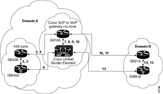
The gatekeeper in Domain A and the gatekeeper in Domain B are connected to the via-zone gatekeeper. GK408 and the via-zone gatekeeper exchange Registration, Admission, and Status (RAS) messages for the originating side. Then the connection is made between the originating gateway and the Cisco Unified Border Element. The via-zone gatekeeper exchanges RAS messages with GK919 for the terminating side. If the call is accepted, the Cisco Unified Border Element completes the connection from GW408 to GW919, and the media flows through the Cisco Unified Border Element.
In a basic call scenario, on receiving a location request (LRQ) message from the originating gatekeeper (GK408), the via-zone-enabled gatekeeper (GKVIA) processes the message and determines that the call should be set up using the Cisco Unified Border Element. After the originating gateway receives its admission confirmation (ACF) message, it sets up the call.
With the Cisco Unified Border Element feature, instead of the originating gateway signaling the terminating gateway directly, the Cisco Unified Border Element controls the call set-up both the signaling and media channel. The Cisco Unified Border Element is terminating the signaling and media channels, but the information associated with the media is propagated through to the opposite call leg. This process allows the endpoints to determine what media channel capabilities to use for the call. When the call is established, the audio stream flows through the Cisco Unified Border Element, meaning that the gateway terminates the audio channel on one call leg and then reorginates it to the other leg.
The following scenario illustrates a basic call from the originating gateway to the terminating gateway, using the Cisco Unified Border Element and gatekeepers.
- GW408 (the originating gateway) calls someone in the 919 area code, which is serviced by GW919 (the terminating gateway).
- GW408 sends an ARQ with the called number having the 919 area code to a gatekeeper in its zone (GK408).
- GK408 resolves 919 to belong to a via-zone gatekeeper (GKVIA). GK408 then sends an LRQ to GKVIA.
- GKVIA receives the LRQ for the 919 number. GKVIA resolves the 919 prefix to belong to the Cisco Unified Border Element. GKVIA is configured to route requests for 919 prefix calls through its Cisco Unified Border Element. GKVIA sends an LCF to GK408.
- GK408 returns an ACF specifying Cisco Unified Border Element to GW408.
- GW408 sends a SETUP message to Cisco Unified Border Element for the 919 number.
- Cisco Unified Border Element consults GKVIA with an ARQ message with the answerCall=true parameter to admit the incoming call.
- GKVIA responds with an ACF to admit the call. From the perspective of the gatekeeper, the first call leg has been established.
- Cisco Unified Border Element has a dial peer specifying that RAS messages should be sent to GKVIA for all prefixes. Cisco Unified Border Element initiates the resending of the call by sending the ARQ message with the answerCall parameter set to, false to GKVIA for 919.
- GKVIA knows that prefix 919 belongs to GK919, and since the source zone is the via-zone, the GKVIA sends an LRQ to GK919.
- GK919 sees prefix 919 as a local zone and sends an LCF pointing to GW919.
- GKVIA returns an ACF specifying GW919.
- Cisco Unified Border Element sends a SETUP message to GW919 for the 919 call.
- GW919 sends an ARQ to GK919 to request admission for the call.
- GK919 sends an ACF with the answerCall=true parameter.
All other messages (for example, Proceeding, Alerting, and Connect) are created as two legs between GW408, and GW919, with the Cisco Unified Border Element acting as an intermediate gateway.
Basic SIP-to-SIP Set-up and Functionality Features
This chapter contains the following configuration topics:
SIP-to-SIP Set-up
- IP-to-IP Gateway: SIP-SIP Basic Functionality
- Transport Control Protocol (TCP) and User Datagram Protocol (UDP) -- http://www.cisco.com/en/US/docs/ios-xml/ios/voice/vcr5/vcr-t3.html#GUID-90074126-D070-4532-8699-CC98C020DA08
- Cisco Unified Border Element and Cisco Unified Communications Manager Express Support for Universal Packaging -- http://www.cisco.com/en/US/docs/ios-xml/ios/voice/vcr3/vcr-m3.html#GUID-F7169012-D016-4AE1-9AFA-4BAB1C6B4182
IP Addressing
Basic Dial Plan Management
Basic Protocol and DTMF Interworking
Lawful Intercept Support
Lawful Intercept (LI) is the term used to describe the process by which law enforcement agencies conduct electronic surveillance of circuit communications as authorized by judicial or administrative order. Cisco Service Independent Intercept (SII) supports voice and data intercept and intercept requests are initiated by MD using SNMPv3.
Cisco and the Cisco logo are trademarks or registered trademarks of Cisco and/or its affiliates in the U.S. and other countries. To view a list of Cisco trademarks, go to this URL: www.cisco.com/go/trademarks. Third-party trademarks mentioned are the property of their respective owners. The use of the word partner does not imply a partnership relationship between Cisco and any other company. (1110R)
Any Internet Protocol (IP) addresses and phone numbers used in this document are not intended to be actual addresses and phone numbers. Any examples, command display output, network topology diagrams, and other figures included in the document are shown for illustrative purposes only. Any use of actual IP addresses or phone numbers in illustrative content is unintentional and coincidental.
 Feedback