MPLS Layer 3 VPNs: Inter-AS and CSC Configuration Guide, Cisco IOS Release 12.2SY
Bias-Free Language
The documentation set for this product strives to use bias-free language. For the purposes of this documentation set, bias-free is defined as language that does not imply discrimination based on age, disability, gender, racial identity, ethnic identity, sexual orientation, socioeconomic status, and intersectionality. Exceptions may be present in the documentation due to language that is hardcoded in the user interfaces of the product software, language used based on RFP documentation, or language that is used by a referenced third-party product. Learn more about how Cisco is using Inclusive Language.
- Updated:
- October 25, 2011
Chapter: MPLS VPN Interautonomous System Support
- Finding Feature Information
- Prerequisites for MPLS VPN - Interautonomous System Support
- Restrictions for MPLS VPN - Interautonomous System Support
- Information About MPLS VPN - Interautonomous System Support
- How to Configure MPLS VPN - Interautonomous System Support
- Configuring eBGP Routing to Exchange MPLS VPN Routes Between Subautonomous Systems in a Confederation
- Verifying Inter-AS for ASBRs Exchanging MPLS VPN-IPv4 Addresses
- Configuring eBGP Multipath Load Sharing for MPLS VPN Inter-AS ASBRs
- Verifying eBGP Multipath Load Sharing for MPLS VPN Inter-AS ASBRs
- Configuring Inter-AS with ASBRs Exchanging VPN-IPv4 Addresses Example
- Configuration for Autonomous System 1 CE1 Example for Two Autonomous Systems
- Configuration for Autonomous System 1 PE1 Example for Two Autonomous Systems
- Configuration for Autonomous System 1 P1 Example for Two Autonomous Systems
- Configuration for Autonomous System 1 ASBR1 Example for Two Autonomous Systems
- Configuration for Autonomous System 2 ASBR2 Example for Two Autonomous Systems
- Configuration for Autonomous System 2 P2 Example for Two Autonomous Systems
- Configuration for Autonomous System 2 PE2 Example for Two Autonomous Systems
- Configuration for Autonomous System 2 CE2 Example for Two Autonomous Systems
- Configuring Inter-AS with ASBRs in a Confederation Example
- Inter-AS Confederation Configuration for Autonomous System 1 CE1 Example
- Inter-AS Confederation Configuration for Autonomous System 1 PE1 Example
- Inter-AS Confederation Configuration for Autonomous System 1 P1 Example
- Inter-AS Confederation Configuration for Autonomous System 1 ASBR1 Example
- Inter-AS Confederation Configuration for Autonomous System 2 ASBR2 Example
- Inter-AS Confederation Configuration for Autonomous System 2 P2 Example
- Inter-AS Confederation Configuration for Autonomous System 2 PE2 Example
- Inter-AS Confederation Configuration for Autonomous System 2 CE2 Example
- Configuring eBGP Multipath Load Sharing for MPLS VPN Inter-AS ASBRs Example
- Multipath Support for Inter-AS VPNs Configuration for Autonomous System 1 CE1 Example
- Multipath Support for Inter-AS VPNs Configuration for Autonomous System 1 PE1 Example
- Multipath Support for Inter-AS VPNs Configuration for Autonomous System 1 P1 Example
- Multipath Support for Inter-AS VPNs Configuration for Autonomous System 1 ASBR1 Example
- Multipath Support for Inter-AS VPNs Configuration for Autonomous System 2 ASBR2 Example
- Multipath Support for Inter-AS VPNs Configuration for Autonomous System 2 ASBR3 Example
- Multipath Support for Inter-AS VPNs Configuration for Autonomous System 2 P2 Example
- Multipath Support for Inter-AS VPNs Configuration for Autonomous System 2 PE2 Example
- Multipath Support for Inter-AS VPNs Configuration for Autonomous System 2 CE2 Example
MPLS VPN - Interautonomous System Support
An autonomous system is a single network or group of networks that is controlled by a common system administration group and that uses a single, clearly defined routing protocol. The MPLS VPN - Interautonomous System Support feature allows an Multiprotocol Label Switching (MPLS) Virtual Private Network (VPN) to span service providers and autonomous systems.
This document explains how to enable Autonomous System Boundary Routers (ASBRs) to use exterior Border Gateway Protocol (eBGP) to exchange IPv4 Network Layer Reachability Information (NLRI) in the form of VPN-IPv4 addresses.
As VPNs grow, their requirements expand. In some cases, VPNs need to reside on different autonomous systems in different geographic areas. Also, some VPNs need to extend across multiple service providers (overlapping VPNs). Regardless of the complexity and location of the VPNs, the connection between autonomous systems must be seamless to the customer. The MPLS VPN - Interautonomous System Support feature provides this functionality.
Finding Feature Information in This Module
Your Cisco IOS software release may not support all of the features documented in this module. To reach links to specific feature documentation in this module and to see a list of the releases in which each feature is supported, use the Feature Information for MPLS VPN - Interautonomous System Support.
Finding Support Information for Platforms and Cisco IOS and Catalyst OS Software Images
Use Cisco Feature Navigator to find information about platform support and Cisco IOS and Catalyst OS software image support. To access Cisco Feature Navigator, go to http://www.cisco.com/go/cfn . An account on Cisco.com is not required.
- Finding Feature Information
- Prerequisites for MPLS VPN - Interautonomous System Support
- Restrictions for MPLS VPN - Interautonomous System Support
- Information About MPLS VPN - Interautonomous System Support
- How to Configure MPLS VPN - Interautonomous System Support
- Configuration Examples for MPLS VPN - Interautonomous System Support
- Additional References
- Feature Information for MPLS VPN - Interautonomous System Support
- Glossary
Finding Feature Information
Your software release may not support all the features documented in this module. For the latest feature information and caveats, see the release notes for your platform and software release. To find information about the features documented in this module, and to see a list of the releases in which each feature is supported, see the Feature Information Table at the end of this document.
Use Cisco Feature Navigator to find information about platform support and Cisco software image support. To access Cisco Feature Navigator, go to www.cisco.com/go/cfn. An account on Cisco.com is not required.
Prerequisites for MPLS VPN - Interautonomous System Support
Before you configure eBGP routing between autonomous systems or subautonomous systems in an MPLS VPN, ensure that you have properly configured all MPLS VPN routing instances and sessions. The configuration tasks outlined in the How to Configure MPLS VPN - Interautonomous System Support build from those configuration tasks.
Perform (as appropriate to the existing network configuration) the following tasks as described in the the Configuring MPLS VPNs feature module.
- Define VPN routing instances
- Configure BGP routing sessions in the service provider (P) network
- Configure provider edge (PE) to PE routing sessions in the service provider (P) network
- Configure BGP PE to customer edge (CE) routing sessions
A VPN-IPv4 eBGP session must be configured between directly connected ASBRs.
This feature is supported on the Cisco IOS 12000 series line cards listed in the table below.
| Table 1 | Cisco I2000 Series Line Card Support Added for Cisco IOS Releases |
| Type |
Line Cards |
Cisco IOS Release Added |
|---|---|---|
| Packet over SONET (POS) |
4-Port OC-3 POS 1-Port OC-12 POS 8-Port OC-3 POS 16-Port OC-3 POS 4-Port OC-12 POS 1-Port OC-48 POS 4-Port OC-3 POS ISE 8-Port OC-3 POS ISE 16-Port OC-3 POS ISE 4-Port OC-12 POS ISE 1-Port OC-48 POS ISE |
12.0(16)ST 12.0(17)ST 12.0(22)S |
| Electrical Interface |
6-Port DS3 12-Port DS3 6-Port E3 12-Port E3 |
12.0(21ST 12.0(22)S |
| Ethernet |
3-Port GbE 1-Port 10-GbE Modular GbE/FE |
12.0(23)S 12.0(24)S |
| ATM |
4-Port OC-3 ATM 1-Port OC12 ATM 4-Port OC-12 ATM 8-Port OC-3 ATM |
12.0(16)ST 12.0(17)ST 12.0(23)S |
| Channelized Interface |
2-Port CHOC-3 6-Port Ch T3 (DS1) 1-Port CHOC-12 (DS3) 1-Port CHOC-12 (OC-3) 4-Port CHOC-12 ISE 1-Port CHOC-48 ISE |
12.0(22)S |
Restrictions for MPLS VPN - Interautonomous System Support
Note the following restrictions to the MPLS VPN - Interautonomous System Support feature:
- A VPN-IPv4 eBGP session must be configured between directly connected ASBRs.
- For networks configured with eBGP multihop, a label switched path (LSP) must be established between nonadjacent routers (RFC 3107).
- PPP encapsulation on the ASBRs is not supported with this feature.
Information About MPLS VPN - Interautonomous System Support
- MPLS VPN Interautonomous System Benefits
- Interautonomous System Communication with ASBRs
- Interautonomous System Configurations Supported in an MPLS VPN
- How Information Is Exchanged in an MPLS VPN Inter-AS with ASBRs
- Load Sharing with MPLS VPN Inter-AS ASBRs
MPLS VPN Interautonomous System Benefits
An MPLS VPN Inter-AS provides the following benefits:
- Allows a VPN to cross more than one service provider backbone--Service providers running separate autonomous systems can jointly offer MPLS VPN services to the same end customer. A VPN can begin at one customer site and traverse different VPN service provider backbones before arriving at another site of the same customer. Before the release of this feature, MPLS VPN could only traverse a single BGP autonomous system service provider backbone. The MPLS VPN - Interautonomous System Support feature allows multiple autonomous systems to form a continuous (and seamless) network between customer sites of a service provider.
- Allows a VPN to exist in different areas--A service provider can create a VPN in different geographic areas. Having all VPN traffic flow through one point (between the areas) allows for better rate control of network traffic between the areas.
- Allows confederations to optimize internal Border Gateway Protocol (iBGP) meshing--iBGP meshing in an autonomous system is more organized and manageable. You can divide an autonomous system into multiple, separate subautonomous systems and then classify them into a single confederation (even though the entire VPN backbone appears as a single autonomous system). This capability allows a service provider to offer MPLS VPNs across the confederation because it supports the exchange of labeled VPN-IPv4 NLRI between the subautonomous systems that form the confederation.
Interautonomous System Communication with ASBRs
Separate autonomous systems from different service providers can communicate by exchanging IPv4 NLRI in the form of VPN-IPv4 addresses. The ASBRs use eBGP to exchange that information. Then an Interior Gateway Protocol (IGP) distributes the network layer information for VPN-IPv4 prefixes throughout each VPN and each autonomous system. Routing information uses the following protocols:
- Within an autonomous system, routing information is shared using an IGP.
- Between autonomous systems, routing information is shared using an eBGP. An eBGP allows a service provider to set up an interdomain routing system that guarantees the loop-free exchange of routing information between separate autonomous systems.
The primary function of an eBGP is to exchange network reachability information between autonomous systems, including information about the list of autonomous system routes. The autonomous systems use EGBP border edge routers to distribute the routes, which include label switching information. Each border edge router rewrites the next hop and MPLS labels. See the How Information Is Exchanged in an MPLS VPN Inter-AS with ASBRs section for more information.
Interautonomous System Configurations Supported in an MPLS VPN
Interautonomous system configurations supported in an MPLS VPN can include:
- Interprovider VPN--MPLS VPNs that include two or more autonomous systems, connected by separate border edge routers. The autonomous systems exchange routes using eBGP. No IGP or routing information is exchanged between the autonomous systems.
- BGP confederations--MPLS VPNs that divide a single autonomous system into multiple subautonomous systems, and classify them as a single, designated confederation. The network recognizes the confederation as a single autonomous system. The peers in the different autonomous systems communicate over eBGP sessions; however, they can exchange route information as if they were iBGP peers.
How Information Is Exchanged in an MPLS VPN Inter-AS with ASBRs
This section contains the following topics about how information is exchanged in an MPLS VPN Inter-AS with ASBRs exchanging VPN-IPv4 addresses:
- Information Sent in an MPLS VPN Inter-AS with ASBRs
- VPN Routing Information Exchange in an MPLS VPN Inter-AS with ASBRs
- Packet Forwarding Between MPLS VPN Interautonomous Systems with ASBRs
- Confederation Configuration for MPLS VPN Inter-AS with ASBRs
Information Sent in an MPLS VPN Inter-AS with ASBRs
The figure below illustrates one MPLS VPN consisting of two separate autonomous systems. Each autonomous system operates under different administrative control and runs a different IGP. Service providers exchange routing information through eBGP border edge routers (ASBR1, ASBR2).
| Figure 1 | eBGP Connection Between Two MPLS VPN Interautonomous Systems with ASBRs Exchanging VPN-IPv4 Addresses |
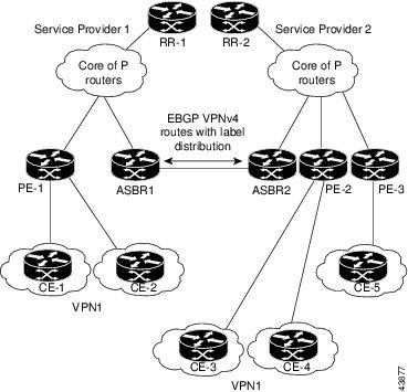
The table below describes the process to transmit information in an Inter-As configuration with ASBRs exchanging VPN-IPv4 addresses.
| Table 2 | Information Transmission Process in an Inter-AS with ASBRs Exchanging VPN-IPv4 AddressesMPLS VPN - Interautonomous System Support |
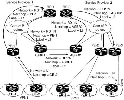
VPN Routing Information Exchange in an MPLS VPN Inter-AS with ASBRs
Autonomous systems exchange VPN routing information (routes and labels) to establish connections. To control connections between autonomous systems, the PE routers and eBGP border edge routers maintain a Label Forwarding Information Base (LFIB).
The LFIB manages the labels and routes that the PE routers and eBGP border edge routers receive during the exchange of VPN information.
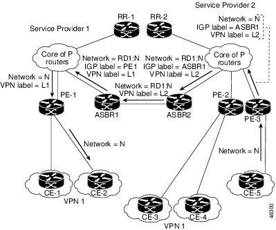
The figure below illustrates the exchange of VPN route and label information between autonomous systems. The autonomous systems use the following guidelines to exchange VPN routing information:
- Routing information:
- An RD1: route distinguisher is part of a destination network address. It makes the VPN-IPv4 route globally unique in the VPN service provider environment.
- The ASBRs are configured to change the next hop (next-hop-self) when sending VPN-IPv4 NLRIs to the iBGP neighbors. Therefore, the ASBRs must allocate a new label when they forward the NLRI to the iBGP neighbors.
| Figure 2 | Exchanging Routes and Labels Between MPLS VPN Inter-AS Systems with ASBRs Exchanging VPN-IPv4 Addresses |
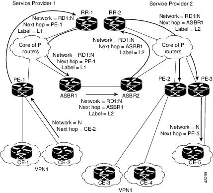
The figure below illustrates the exchange of VPN route and label information between autonomous systems. The only difference is that ASBR2 is configured with the redistribute connected command, which propagates the host routes to all PEs. The redistribute connected command is necessary because ASBR2 is not configured to change the next-hop address.
| Figure 3 | Exchanging Routes and Labels with the redistributed connected Command in an MPLS VPN Inter-AS with ASBRs Exchanging VPN-IPv4 Addresses |
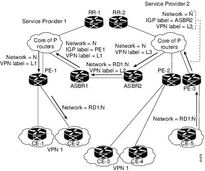
Packet Forwarding Between MPLS VPN Interautonomous Systems with ASBRs
The figure below illustrates how packets are forwarded between autonomous systems in an interprovider network using the following packet forwarding method.
Packets are forwarded to their destination by means of MPLS. Packets use the routing information stored in the LFIB of each PE router and eBGP border edge router.
The service provider VPN backbone uses dynamic label switching to forward labels.
Each autonomous system uses standard multilevel labeling to forward packets between the edges of the autonomous system routers (for example, from CE-5 to PE-3). Between autonomous systems, only a single level of labeling is used, corresponding to the advertised route.
A data packet carries two levels of labels when traversing the VPN backbone:
- The first label (IGP route label) directs the packet to the correct PE router or eBGP border edge router. (For example, the IGP label of ASBR2 points to the ASBR2 border edge router.)
- The second label (VPN route label) directs the packet to the appropriate PE router or eBGP border edge router.
| Figure 4 | Packet Forwarding Between MPLS VPN Interautonomous Systems with ASBRs Exchanging VPN-IPv4 Addresses |
The figure below shows the same packet forwarding method, except the eBGP router (ASBR1) forwards the packet without reassigning it a new label.
| Figure 5 | Forwarding Packets Without a New Label Assignment Between MPLS VPN Interautonomous Systems with ASBRs Exchanging VPN-IPv4 Addresses |
Confederation Configuration for MPLS VPN Inter-AS with ASBRs
A confederation is multiple subautonomous systems grouped together. A confederation reduces the total number of peer devices in an autonomous system. A confederation divides an autonomous system into subautonomous systems and assigns a confederation identifier to the autonomous systems. A VPN can span service providers running in separate autonomous systems or in multiple subautonomous systems that form a confederation.
In a confederation, each subautonomous system is fully meshed with other subautonomous systems. The subautonomous systems communicate using an IGP, such as Open Shortest Path First (OSPF) or Intermediate System-to-Intermediate System (IS-IS). Each subautonomous system also has an eBGP connection to the other subautonomous systems. The confederation eBGP (CeBGP) border edge routers forward next-hop-self addresses between the specified subautonomous systems. The next-hop-self address forces the BGP to use a specified address as the next hop rather than letting the protocol choose the next hop.
You can configure a confederation with separate subautonomous systems in either of two ways:
- You can configure a router to forward next-hop-self addresses between only the CeBGP border edge routers (both directions). The subautonomous systems (iBGP peers) at the subautonomous system border do not forward the next-hop-self address. Each subautonomous system runs as a single IGP domain. However, the CeBGP border edge router addresses are known in the IGP domains.
- You can configure a router to forward next-hop-self addresses between the CeBGP border edge routers (both directions) and within the iBGP peers at the subautonomous system border. Each subautonomous system runs as a single IGP domain but also forwards next-hop-self addresses between the PE routers in the domain. The CeBGP border edge router addresses are known in the IGP domains.
 Note |
The second and third figures above illustrate how two autonomous systems exchange routes and forward packets. Subautonomous systems in a confederation use a similar method of exchanging routes and forwarding packets. |
The figure below illustrates a typical MPLS VPN confederation configuration. In this confederation configuration:
- The two CeBGP border edge routers exchange VPN-IPv4 addresses with labels between the two subautonomous systems.
- The distributing router changes the next-hop addresses and labels and uses a next-hop-self address.
IGP-1 and IGP-2 know the addresses of CeBGP-1 and CeBGP-2.
| Figure 6 | eBGP Connection Between Two Subautonomous Systems in a Confederation |
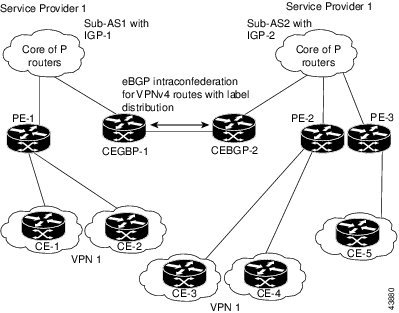
In this confederation configuration:
- CeBGP border edge routers function as neighboring peers between the subautonomous systems. The subautonomous systems use eBGP to exchange route information.
- Each CeBGP border edge router (CeBGP-1, CeBGP-2) assigns a label for the route before distributing the route to the next subautonomous system. The CeBGP border edge router distributes the route as a VPN-IPv4 address by using the multiprotocol extensions of BGP. The label and the VPN identifier are encoded as part of the NLRI.
- Each PE and CeBGP border edge router assigns its own label to each VPN-IPv4 address prefix before redistributing the routes. The CeBGP border edge routers exchange VPN-IPv4 addresses with the labels. The next-hop-self address is included in the label (as the value of the eBGP next-hop attribute). Within the subautonomous systems, the CeBGP border edge router address is distributed throughout the iBGP neighbors, and the two CeBGP border edge routers are known to both confederations.
Load Sharing with MPLS VPN Inter-AS ASBRs
Before the MPLS VPN - Interautonomous System Support feature, if multiple paths existed across ASBRs, BGP executed the best path algorithm and marked only one of the paths as the best path. This path was added to the routing table and became the only path that was used for forwarding traffic between ASBRs.
The MPLS VPN--Multipath Support for Inter-AS VPNs feature extends the functionality of BGP so that it can pick one path as the best path and mark the other legitimate paths between ASBRs as multipath. This allows the load sharing of traffic among the different multipaths and the best path to reach the destination. No Routing Information Base (RIB) or Cisco Express Forwarding entries are associated with the VPN-IPv4 prefixes.
The MPLS VPN--Multipath Support for Inter-AS VPNs feature applies to ASBRs that do not have a VPN routing and forwarding (VRF) instance configuration. BGP installs a number of learned VPN-IPv4 prefixes into the MPLS forwarding table (LFIB). VPN-IPv4 entries in the LFIB consist of the Route Distinguisher (RD) and the IPv4 prefix and are called VPNv4 entries.
The maximum-paths command is used to set the number of parallel (equal-cost) routes that BGP installs in the routing table to configure multipath load sharing. The number of paths that can be configured is determined by the version of Cisco IOS software. The following list shows the limits:
- Cisco IOS Release 12.0S-based software: 8 paths
- Cisco IOS Release 12.3T-based software: 16 paths
- Cisco IOS Release 12.2S-based software: 32 paths
The MPLS VPN--Multipath Support for Inter-AS VPNs feature requires that you configure the maximum-paths number-of-paths command in address family configuration mode.
Note |
The maximum-paths command cannot be configured with the maximum-paths eibgp command for the same BGP routing process. |
The figure below shows an example of VPNv4 load balancing for ASBRs in an Inter-AS network. In this example, ASBR1 load balances the traffic from the CE router CE1 to CE2 using the two available links--ASBR2 and ASBR3.
| Figure 7 | Example of VPNv4 Load Balancing for ASBRs in an Inter-AS Network |
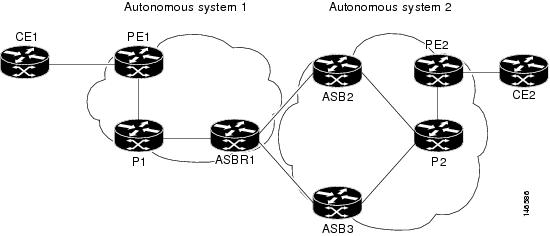
When you configure an ASBR for VPNv4 load balancing, you must configure the next-hop-self command for the iBGP peers. Without this command, the next hop that is propagated to the iBGP peer is the ASBR2 address or the ASBR3 address, depending on which one BGP selects as the best path. Configuring the next-hop-self command provides direct VPNv4 forwarding entries in the MPLS forwarding table for the VPNv4 prefixes learned from the remote ASBRs. VPNv4 forwarding entries are not created if you do not configure the next-hop-self command.
Note |
If the number of forwarding entries in the MPLS forwarding table on the system or on a line card is a concern for your network, we recommend that you do not enable VPNv4 multipath on ASBRs. |
How to Configure MPLS VPN - Interautonomous System Support
Perform the following tasks to configure MPLS VPN Inter-AS with ASBRs exchanging VPN-IPv4 addresses:
- Configuring an eBGP ASBR to Exchange MPLS VPN-IPv4 Addresses
- Configuring eBGP Routing to Exchange MPLS VPN Routes Between Subautonomous Systems in a Confederation
- Verifying Inter-AS for ASBRs Exchanging MPLS VPN-IPv4 Addresses
- Configuring eBGP Multipath Load Sharing for MPLS VPN Inter-AS ASBRs
- Verifying eBGP Multipath Load Sharing for MPLS VPN Inter-AS ASBRs
Configuring an eBGP ASBR to Exchange MPLS VPN-IPv4 Addresses
Perform one of the following tasks to configure an eBGP ASBR to exchange MPLS VPN-IPv4 routes with another autonomous system:
- Configuring Peering with Directly Connected Interfaces Between ASBRs
- Configuring Peering of the Loopback Interface of Directly Connected ASBRs
Configuring Peering with Directly Connected Interfaces Between ASBRs
Perform this task to configure peering with directly connected interfaces between ASBRs so that the ASBRs can distribute BGP routes with MPLS labels.
The figure below shows the configuration for the peering with directly connected interfaces between ASBRs. This configuration is used as the example in the tasks that follow.
| Figure 8 | Configuration for Peering with Directly Connected Interfaces Between ASBRs |
Note |
When eBGP sessions come up, BGP automatically generates the mpls bgp forwarding command on the connecting interface. |
Note |
Issue the redistribute connected subnets command in the IGP configuration portion of the router to propagate host routes for VPN-IPv4 eBGP neighbors to other routers and provider edge routers. Alternatively, you can specify the next-hop-self address when you configure iBGP neighbors. |
DETAILED STEPS
Configuring Peering of the Loopback Interface of Directly Connected ASBRs
This functionality is provided with the release of the MPLS VPN - Interautonomous System Support feature on Cisco IOS Release 12.0(29)S and later releases. An eBGP session configured between loopbacks of directly connected ASBRs allows load sharing between loopback addresses.
Perform the following tasks in this section to configure peering of loopback interfaces of directly connected ASBRs:
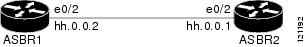
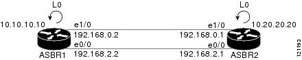
The figure below shows the loopback configuration for directly connected ASBR1 and ASBR2 routers. This configuration is used as the example in the tasks that follow.
| Figure 9 | Loopback Interface Configuration for Directly Connected ASBR1 and ASBR2 Routers |
- Configuring Loopback Interface Addresses for Directly Connected ASBRs
- Examples
- Configuring Static Routes to the eBGP Neighbor Loopback
- Examples
- Configuring Forwarding on the Directly Connected Interfaces
- Examples
- Configuring an eBGP Session Between the Loopbacks
- Examples
Configuring Loopback Interface Addresses for Directly Connected ASBRs
Perform the following task to configure loopback interface addresses for directly connected ASBRs.
Note |
Loopback addresses need to be configured for each directly connected ASBR. That is, configure a loopback address for ASBR1 and for ASBR2 (see the figure above). |
DETAILED STEPS
Examples
The following example shows the configuration of a loopback address for ASBR1:
configure terminal
interface loopback 0
 ip address 10.10.10.10 255.255.255.255
The following example shows the configuration of a loopback address for ASBR2:
configure terminal
interface loopback 0
 ip address 10.20.20.20 255.255.255.255
Configuring Static Routes to the eBGP Neighbor Loopback
Perform the following task to configure /32 static routes to the eBGP neighbor loopback.
A /32 static route is established with the following commands:
Router(config)# ip route X.X.X.X 255.255.255.255 Ethernet 1/0 Y.Y.Y.Y
Router(config)# ip route X.X.X.X 255.255.255.255 Ethernet 1/0 Z.Z.Z.Z
Where X.X.X.X is the neighboring loopback address and Ethernet 1/0 and Ethernet 0/0 are the links connecting the peering routers. Y.Y.Y.Y and Z.Z.Z.Z are the respective next-hop addresses on the interfaces.
Note |
You need to configure /32 static routes on each of the directly connected ASBRs. |
DETAILED STEPS
Examples
The following example shows the configuration of a /32 static route from the ASBR1 router to the loopback address of the ASBR2 router:
configure terminal
ip route 10.20.20.20 255.255.255.255 e1/0 192.168.0.1
ip route 10.20.20.20 255.255.255.255 e0/0 192.168.2.1
The following example shows the configuration of a /32 static route from the ASBR2 router to the loopback address of the ASBR1 router:
configure terminal
ip route vrf vpn1 10.10.10.10 255.255.255.255 Ethernet 1/0 192.168.0.2
ip route vrf vpn1 10.10.10.10 255.255.255.255 Ethernet 0/0 192.168.2.2
Configuring Forwarding on the Directly Connected Interfaces
Perform this task to configure forwarding on the directly connected interfaces.
This task is required for sessions between loopbacks. In the Configuring Static Routes to the eBGP Neighbor Loopback task, Ethernet 1/0 and Ethernet 0/0 are the connecting interfaces.
DETAILED STEPS
Examples
The following example shows the configuration of BGP MPLS forwarding on the interfaces connecting the ASBR1 router with the ASBR2 router:
configure terminal
interface ethernet 1/0
 ip address 192.168.0.2 255.255.255.0
 mpls bgp forwarding
 exit
!
interface ethernet 0/0
 ip address 192.168.2.2 255.255.255.0
 mpls bgp forwarding
 exit
The following example shows the configuration of BGP MPLS forwarding on the interfaces connecting the ASBR2 router with the ASBR1 router:
configure terminal
interface ethernet 1/0
 ip address 192.168.0.1 255.255.255.0
 mpls bgp forwarding
 exit
!
interface ethernet 0/0
 ip address 192.168.2.1 255.255.255.0
 mpls bgp forwarding
 exit
Configuring an eBGP Session Between the Loopbacks
Perform the following tasks to configure an eBGP session between the loopbacks.
Note |
You need to configure an EGBP session between loopbacks on each directly connected ASBR. |
DETAILED STEPS
Examples
The following example shows the configuration for VPNv4 sessions on the ASBR1 router:
configure terminal
router bgp 200
 bgp log-neighbor-changes
 neighbor 10.20.20.20 remote-as 100
 neighbor 10.20.20.20 disable-connected-check
 neighbor 10.20.20.20 update-source loopback 0
!
 address-family vpnv4
 neighbor 10.20.20.20 activate
 neighbor 10.20.20.20 send-community extended
 end
The following example shows the configuration for VPNv4 sessions on the ASBR2:
configure terminal
router bgp 100
 bgp log-neighbor-changes
 neighbor 10.10.10.10 remote-as 200
 neighbor 10.10.10.10 disable-connected-check
 neighbor 10.10.10.10 update-source Loopback 0
!
 address-family vpnv4
 neighbor 10.10.10.10 activate
 neighbor 10.10.10.10 send-community extended
 end
Configuring eBGP Routing to Exchange MPLS VPN Routes Between Subautonomous Systems in a Confederation
Perform this task to configure eBGP routing to exchange MPLS VPN routes between subautonomous systems in a confederation.
Note |
To ensure that the host routes for VPN-IPv4 eBGP neighbors are propagated (by means of the IGP) to the other routers and provider edge routers, specify the redistribute connected command in the IGP configuration portion of the CeBGP router. If you are using OSPF, make sure that the OSPF process is not enabled on the CeBGP interface where the "redistribute connected" subnet exists. |
Note |
In this confederation, subautonomous system IGP domains must know the addresses of CeBGP-1 and CeBGP-2. If you do not specify a next-hop-self address as part of the router configuration, ensure that the addresses of all PE routers in the subautonomous system are distributed throughout the network, not just the addresses of CeBGP-1 and CeBGP-2. |
DETAILED STEPS
Verifying Inter-AS for ASBRs Exchanging MPLS VPN-IPv4 Addresses
Perform this task to verify that Inter-AS for ASBRs Exchanging MPLS VPN-IPv4 addresses operates as you expected.
DETAILED STEPS
Configuring eBGP Multipath Load Sharing for MPLS VPN Inter-AS ASBRs
Perform this task to configure eBGP multipath load sharing for MPLS VPN Inter-AS ASBRs exchanging VPN-IPv4 routes. This allows for more efficient use of the LSPs in an interautonomous system network because you can set up the load sharing of traffic among the different multipaths and the best path to reach the destination.
Note |
The following restrictions apply to configuring multipath load sharing for MPLS VPN Inter-AS ASBRS exchanging VPN-IPv4 routes:
The figure below shows an eBGP multipath configuration for three VPN-IPv4 ASBRs. The links from ASBR1 to ASBR2 and ASBR3 have an eBGP VPN-IPv4 session configured. In the figure below, eBGP multipath load sharing is configured on ASBR1. You configure the number of sessions from ASBR1 to ASBR2 and ASBR3 with the maximum-paths command in address family configuration mode.
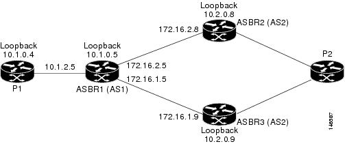
The configurations in the figure above is used as an example for this task and for the task in the Verifying eBGP Multipath Load Sharing for MPLS VPN Inter-AS ASBRs. |
DETAILED STEPS
| Command or Action | Purpose | |
|---|---|---|
|
|
Example: Router> enable |
Enables privileged EXEC mode. |
|
|
Example: Router# configure terminal |
Enters global configuration mode. |
|
|
Example: Router(config)# router bgp 1 |
Configures an eBGP routing process and places the router in router configuration mode. |
|
|
Example: Router(config-router)# no bgp default route-target filter |
Disables BGP route-target community filtering. All received VPN-IPv4 routes are accepted by the configured router. Accepting VPN-IPv4 routes is the desired behavior for a router configured as an ASBR. |
|
|
Example: Router(config-router)# neighbor 10.1.0.4 remote-as 1 |
Adds an entry to the BGP or multiprotocol BGP neighbor table. |
|
|
Example: Router(config-router)# neighbor 10.1.0.4 update-source loopback 0 |
Allows BGP sessions to use any operational interface for TCP connections.
This example shows how to set up BGP TCP connections for the specified neighbor with the IP address of the loopback interface rather than the best local address. |
|
|
Example: Router(config-router)# neighbor 10.1.0.4 next-hop-self |
Configures the router as the next hop for a BGP neighbor or peer group. |
|
|
Example: Router(config-router)# neighbor 172.16.1.9 remote-as 2 |
Adds an entry to the BGP or multiprotocol BGP neighbor table. |
|
|
|
-- |
|
|
Example: Router(config-router)# address-family vpnv4 |
Enters address family configuration mode. This command configures a routing session to carry VPN-IPv4 addresses across the VPN backbone. Each address is globally unique by the addition of an 8-byte RD. |
|
|
Example: Router(config-router-af)# neighbor 10.1.0.4 activate |
Enables the exchange of information with a neighboring router. |
|
|
Example: Router(config-router-af)# neighbor 10.1.0.4 next-hop-self |
Configures the router as the next hop for a BGP neighbor or peer group. |
|
|
Example: Router(config-router-af)# neighbor 10.1.0.4 send-community extended |
Specifies that a communities attribute should be sent to a BGP neighbor.
|
|
|
Example: Router(config-router-af)# neighbor 172.16.1.9 activate |
Enables the exchange of information with a BGP neighbor.
This argument must be in the form documented in RFC 2373, where the address is specified in hexadecimal using 16-bit values between colons. |
|
|
Example: Router(config-router-af)# neighbor 172.16.1.9 send-community extended |
Specifies that a communities attribute should be sent to a BGP neighbor.
|
|
|
|
|
|
|
Example: Router(config-router-af)# maximum-paths 2 |
Configures the maximum number of parallel routes that an IP routing protocol will install into the routing table.
|
|
|
Example: Router(config-router-af)# exit-address-family |
Exits from address family configuration mode. |
|
|
Example: Router(config-router)# end |
(Optional) Exits to privileged EXEC mode. |
Examples
The following example shows the configuration for eBGP multipath for VPNv4 sessions on the ASBR1 router:
configure terminal
router bgp 1
 no bgp default route-target filter
 neighbor 10.1.0.4 remote-as 1
 neighbor 10.1.0.4 update-source Loopback 0
 neighbor 10.1.0.4 next-hop-self
 neighbor 172.16.1.9 remote-as 2
 neighbor 172.16.2.8 remote-as 2
!
 address-family vpnv4
 neighbor 10.1.0.4 activate
 neighbor 10.1.0.4 next-hop-self
 neighbor 10.1.0.4 send-community extended
 neighbor 172.16.1.9 activate
 neighbor 172.16.1.9 send-community extended
 neighbor 172.16.2.8 activate
 neighbor 172.16.2.8 send-community extended
 maximum-paths 2
 exit-address-family
 end
Verifying eBGP Multipath Load Sharing for MPLS VPN Inter-AS ASBRs
Perform the following task to verify that eBGP multipath load sharing for MPLS VPN Inter-AS ASBRs is operating as you expect.
The configurations in the figure above are used as an example for the task that follows.
DETAILED STEPS
Configuration Examples for MPLS VPN - Interautonomous System Support
- Configuring Inter-AS with ASBRs Exchanging VPN-IPv4 Addresses Example
- Configuring Inter-AS with ASBRs in a Confederation Example
- Configuring eBGP Multipath Load Sharing for MPLS VPN Inter-AS ASBRs Example
Configuring Inter-AS with ASBRs Exchanging VPN-IPv4 Addresses Example
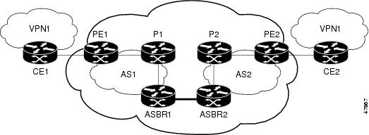
The network topology in the figure below shows two autonomous systems, which are configured as follows:
- Autonomous system 1 (AS1) contains PE1, P1, ASBR1. The IGP is OSPF.
- Autonomous system 2 (AS2) contains PE2, P2, ASBR2. The IGP is IS-IS.
- CE1 and CE2 belong to the same VPN, which is called VPN1.
- The P routers are route reflectors.
- ASBR1 is configured with the redistribute connected subnets command.
- ASBR2 is configured with the neighbor next-hop-self command.
| Figure 11 | Configuring Two Autonomous Systems |
- Configuration for Autonomous System 1 CE1 Example for Two Autonomous Systems
- Configuration for Autonomous System 1 PE1 Example for Two Autonomous Systems
- Configuration for Autonomous System 1 P1 Example for Two Autonomous Systems
- Configuration for Autonomous System 1 ASBR1 Example for Two Autonomous Systems
- Configuration for Autonomous System 2 ASBR2 Example for Two Autonomous Systems
- Configuration for Autonomous System 2 P2 Example for Two Autonomous Systems
- Configuration for Autonomous System 2 PE2 Example for Two Autonomous Systems
- Configuration for Autonomous System 2 CE2 Example for Two Autonomous Systems
Configuration for Autonomous System 1 CE1 Example for Two Autonomous Systems
The following example shows how to configure the CE1 router in VPN1 in a topology with two autonomous systems (see the figure above):
!
hostname CE1
!
interface Loopback 1
 ip address 192.168.0.1 255.255.255.255
!
interface Ethernet 1/0
 description Link to PE1
 ip address 192.168.1.1 255.255.255.0
!
router ospf 1
 log-adjacency-changes
 network 192.168.0.0 0.0.255.255 area 0
!
 end
Configuration for Autonomous System 1 PE1 Example for Two Autonomous Systems
The following example shows how to configure the PE1 router in autonomous system 1 in a topology with two autonomous systems (see the figure above):
!
hostname PE1
!
ip cef
!
ip vrf VPN1
 rd 1:105
 route-target export 1:100
 route-target import 1:100
!
interface Loopback 0
 ip address 10.1.0.3 255.255.255.255
!
interface Ethernet 0/0
 description Link to CE1
 ip vrf forwarding VPN1
 ip address 192.168.1.2 255.255.255.0
!
interface Ethernet 1/0
 description Link to P1
 ip address 10.1.1.3 255.255.255.0
 mpls ip
!
router ospf 10 vrf VPN1
 log-adjacency-changes
 redistribute bgp 1 metric 100 subnets
 network 192.168.0.0 0.0.255.255 area 0
!
router ospf 1
 log-adjacency-changes
 network 10.0.0.0 0.255.255.255 area 0
!
router bgp 1
 no synchronization
 bgp log-neighbor-changes
 neighbor R peer-group
 neighbor R remote-as 1
 no neighbor R transport path-mtu-discovery
 neighbor R update-source Loopback 0
 neighbor 10.1.0.4 peer-group R
 no auto-summary
 !
 address-family vpnv4
 neighbor R send-community extended
 neighbor 10.1.0.4 activate
 exit-address-family
 !
 address-family ipv4 vrf VPN1
 redistribute ospf 10 vrf VPN1
 no auto-summary
 no synchronization
 exit-address-family
!
end
Configuration for Autonomous System 1 P1 Example for Two Autonomous Systems
The following example shows how to configure the P1 router in autonomous system 1 in a topology with two autonomous systems (see the figure above):
!
hostname P1
!
ip cef
!
interface Loopback 0
 ip address 10.1.0.4 255.255.255.255
!
interface Ethernet 0/0
 description Link to PE1
 ip address 10.1.1.4 255.255.255.0
 mpls ip
!
interface Ethernet 1/0
 description Link to ASBR1
 ip address 10.1.2.4 255.255.255.0
 mpls ip
!
router ospf 1
 log-adjacency-changes
 network 10.0.0.0 0.255.255.255 area 0
!
router bgp 1
no synchronization
 bgp log-neighbor-changes
 neighbor R peer-group
 neighbor R remote-as 1
 no neighbor R transport path-mtu-discovery
 neighbor R update-source Loopback 0
 neighbor R route-reflector-client
 neighbor 10.1.0.3 peer-group R
 neighbor 10.1.0.5 peer-group R
 no auto-summary
 !
 address-family vpnv4
 neighbor R send-community extended
 neighbor R route-reflector-client
 neighbor 10.1.0.3 activate
 neighbor 10.1.0.5 activate
 exit-address-family
!
end
Configuration for Autonomous System 1 ASBR1 Example for Two Autonomous Systems
The following example shows how to configure ASBR1 in autonomous system 1 in a topology with two autonomous systems (see the figure above):
hostname ASBR1
!
ip cef
!
interface Loopback 0
 ip address 10.1.0.5 255.255.255.255
!
interface Ethernet 0/0
 description Link to P1
 ip address 10.1.2.5 255.255.255.0
 mpls ip
!
interface Ethernet 1/0
 description Link to ASBR2
 ip address 172.16.0.1 255.255.255.255
 mpls bgp forwarding
!
router ospf 1
 log-adjacency-changes
 redistribute connected subnets
 network 10.0.0.0 0.255.255.255 area 0
!
router bgp 1
 no synchronization
 no bgp default route-target filter
 bgp log-neighbor-changes
 neighbor R peer-group
 neighbor R remote-as 1
 no neighbor R transport path-mtu-discovery
 neighbor R update-source Loopback 0
 neighbor 10.1.0.4 peer-group R
 neighbor 172.16.0.2 remote-as 2
 no auto-summary
 !
 address-family vpnv4
 neighbor R send-community extended
 neighbor R next-hop-self
 neighbor 10.1.0.4 activate
 neighbor 172.16.0.2 activate
 neighbor 172.16.0.2 send-community extended
 exit-address-family
!
end
Configuration for Autonomous System 2 ASBR2 Example for Two Autonomous Systems
The following example shows how to configure ASBR2 in autonomous system 2 in a topology with two autonomous systems (see the figure above):
!
hostname ASBR2
!
ip cef
!
interface Loopback 0
 ip address 10.2.0.8 255.255.255.255
 ip router isis
!
interface Ethernet 0/0
 description Link to ASBR1
 ip address 172.16.0.2 255.255.255.255
 mpls bgp forwarding
!
interface Serial 2/0
 description Link to P2
 ip address 10.2.2.8 255.255.255.0
 ip router isis
 mpls ip
 no fair-queue
 serial restart-delay 0
!
router isis
 net 49.0002.0000.0000.0003.00
!
router bgp 2
 no synchronization
 no bgp default route-target filter
 bgp log-neighbor-changes
 neighbor 10.2.0.7 remote-as 2
 neighbor 10.2.0.7 update-source Loopback 0
 neighbor 10.2.0.7 next-hop-self
 neighbor 172.16.0.1 remote-as 1
 no auto-summary
!
 address-family vpnv4
 neighbor 10.2.0.7 activate
 neighbor 10.2.0.7 send-community extended
 neighbor 10.2.0.7 next-hop-self
 neighbor 172.16.0.1 activate
 neighbor 172.16.0.1 send-community extended
 exit-address-family
!
end
Configuration for Autonomous System 2 P2 Example for Two Autonomous Systems
The following example shows how to configure the P2 router in autonomous system 2 in a topology with two autonomous systems (see the figure above):
!
hostname P2
!
ip cef
!
interface Loopback 0
 ip address 10.2.0.7 255.255.255.255
 ip router isis
!
interface Ethernet 1/0
 description Link to PE2
 ip address 10.2.1.7 255.255.255.0
 ip router isis
 mpls ip
!
interface Serial 2/0
 description Link to ASBR2
 ip address 10.2.2.7 255.255.255.0
 ip router isis
 mpls ip
 no fair-queue
 serial restart-delay 0
!
router isis
 net 49.0002.0000.0000.0008.00
!
router bgp 2
 no synchronization
 bgp log-neighbor-changes
 neighbor R peer-group
 neighbor R remote-as 2
 no neighbor R transport path-mtu-discovery
 neighbor R update-source Loopback 0
 neighbor R route-reflector-client
 neighbor 10.2.0.6 peer-group R
 neighbor 10.2.0.8 peer-group R
 no auto-summary
 !
 address-family vpnv4
 neighbor R send-community extended
 neighbor R route-reflector-client
 neighbor 10.2.0.6 activate
 neighbor 10.2.0.8 activate
 exit-address-family
!
end
Configuration for Autonomous System 2 PE2 Example for Two Autonomous Systems
The following example shows how to configure the PE2 router in autonomous system 2 in a topology with two autonomous systems (see the figure above):
!
hostname PE2
!
ip cef
!
ip vrf VPN1
 rd 1:105
 route-target export 1:100
 route-target import 1:100
!
interface Loopback 0
 ip address 10.2.0.6 255.255.255.255
 ip router isis
!
interface Ethernet 0/0
 description Link to P2
 ip address 10.2.1.6 255.255.255.0
 ip router isis
 mpls ip
!
interface Serial 2/0
 description Link to CE2
 ip vrf forwarding VPN1
 ip address 192.168.2.2 255.255.255.0
 no fair-queue
 serial restart-delay 0
!
router ospf 10 vrf VPN1
 log-adjacency-changes
 redistribute bgp 2 subnets
 network 192.168.0.0 0.0.255.255 area 0
!
router isis
 net 49.0002.0000.0000.0009.00
!
router bgp 2
 no synchronization
 bgp log-neighbor-changes
 neighbor 10.2.0.7 remote-as 2
 neighbor 10.2.0.7 update-source Loopback 0
 no auto-summary
 !
address-family vpnv4
 neighbor 10.2.0.7 activate
 neighbor 10.2.0.7 send-community extended
 exit-address-family
 !
 address-family ipv4 vrf VPN1
 redistribute connected
 redistribute ospf 10 vrf VPN1
 no auto-summary
 no synchronization
 exit-address-family
!
end
Configuration for Autonomous System 2 CE2 Example for Two Autonomous Systems
The following example shows how to configure the CE2 router in autonomous system 2 in a topology with two autonomous systems (see the figure above):
!
hostname CE2
!
interface Loopback 0
 ip address 192.168.0.2 255.255.255.255
!
interface Serial 2/0
 description Link to PE2
 ip address 192.168.2.1 255.255.255.0
 no fair-queue
 serial restart-delay 0
!
router ospf 1
 log-adjacency-changes
 network 192.168.0.0 0.0.255.255 area 0
!
end
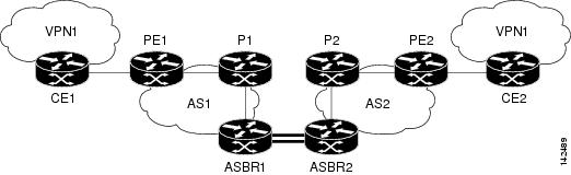
Configuring Inter-AS with ASBRs in a Confederation Example
The network topology in the figure below shows a single Internet service provider (ISP), which is partitioning the backbone with confederations. The autonomous system number of the provider is 100. The two autonomous systems run their own IGPs and are configured as follows:
- Autonomous system 1 (AS1) contains PE1, P1, ASBR1. The IGP is OSPF.
- Autonomous system 2 (AS2) contains PE2, P2, ASBR2. The IGP is IS-IS.
- CE1 and CE2 belong to the same VPN, which is called VPN1.
- The P routers are route reflectors.
- ASBR1 is configured with the redistribute connected subnets command.
- ASBR2 is configured with the neighbor next-hop-self command.
| Figure 12 | Configuring Two Autonomous Systems in a Confederation |
- Inter-AS Confederation Configuration for Autonomous System 1 CE1 Example
- Inter-AS Confederation Configuration for Autonomous System 1 PE1 Example
- Inter-AS Confederation Configuration for Autonomous System 1 P1 Example
- Inter-AS Confederation Configuration for Autonomous System 1 ASBR1 Example
- Inter-AS Confederation Configuration for Autonomous System 2 ASBR2 Example
- Inter-AS Confederation Configuration for Autonomous System 2 P2 Example
- Inter-AS Confederation Configuration for Autonomous System 2 PE2 Example
- Inter-AS Confederation Configuration for Autonomous System 2 CE2 Example
Inter-AS Confederation Configuration for Autonomous System 1 CE1 Example
The following example shows how to configure CE1 in VPN1 in an Inter-AS confederation (see the figure above):
!
hostname CE1
!
interface Loopback 1
 ip address 192.168.0.1 255.255.255.255
!
interface Ethernet 1/0
 description Link to PE1
 ip address 192.168.1.1 255.255.255.0
!
router ospf 1
 log-adjacency-changes
 network 192.168.0.0 0.0.255.255 area 0
!
end
Inter-AS Confederation Configuration for Autonomous System 1 PE1 Example
The following example shows how to configure PE1 in autonomous system 1 in an Inter-AS confederation (see the figure above):
hostname PE1
!
ip cef
!
ip vrf VPN1
 rd 1:105
 route-target export 1:100
 route-target import 1:100
!
interface Loopback 0
 ip address 10.1.0.3 255.255.255.255
!
interface Ethernet 0/0
 description Link to CE1
 ip vrf forwarding VPN1
 ip address 192.168.1.2 255.255.255.0
!
interface Ethernet 1/0
 description Link to P1
 ip address 10.1.1.3 255.255.255.0
 mpls ip
!
router ospf 10 vrf VPN1
 log-adjacency-changes
 redistribute bgp 1 metric 100 subnets
 network 192.168.0.0 0.0.255.255 area 0
!
router ospf 1
 log-adjacency-changes
 network 10.0.0.0 0.255.255.255 area 0
!
router bgp 1
 no synchronization
 bgp log-neighbor-changes
 bgp confederation identifier 100
 neighbor R peer-group
 neighbor R remote-as 1
 no neighbor R transport path-mtu-discovery
 neighbor R update-source Loopback 0
 neighbor 10.1.0.4 peer-group R
 no auto-summary
 !
 address-family vpnv4
 neighbor R send-community extended
 neighbor 10.1.0.4 activate
 exit-address-family
 !
 address-family ipv4 vrf VPN1
 redistribute ospf 10 vrf VPN1
 no auto-summary
 no synchronization
 exit-address-family
!
end
Inter-AS Confederation Configuration for Autonomous System 1 P1 Example
The following example shows how to configure P1 in autonomous system 1 in a confederation topology (see the figure above):
!
hostname P1
!
ip cef
!
interface Loopback 0
 ip address 10.1.0.4 255.255.255.255
!
interface Ethernet 0/0
 description Link to PE1
 ip address 10.1.1.4 255.255.255.0
 mpls ip
!
interface Ethernet 1/0
 description Link to ASBR1
 ip address 10.1.2.4 255.255.255.0
 mpls ip
!
router ospf 1
 log-adjacency-changes
 network 10.0.0.0 0.255.255.255 area 0
!
router bgp 1
 no synchronization
 bgp log-neighbor-changes
 bgp confederation identifier 100
 neighbor R peer-group
 neighbor R remote-as 1
 no neighbor R transport path-mtu-discovery
 neighbor R update-source Loopback 0
 neighbor R route-reflector-client
 neighbor 10.1.0.3 peer-group R
 neighbor 10.1.0.5 peer-group R
 no auto-summary
 !
 address-family vpnv4
 neighbor R send-community extended
 neighbor R route-reflector-client
 neighbor 10.1.0.3 activate
 neighbor 10.1.0.5 activate
 exit-address-family
!
end
Inter-AS Confederation Configuration for Autonomous System 1 ASBR1 Example
The following example shows how to configure ASBR1 in autonomous system 1 in a confederation topology (see the figure above):
!
hostname ASBR1
!
ip cef
!
interface Loopback 0
 ip address 10.1.0.5 255.255.255.255
!
interface Ethernet 0/0
 description Link to P1
 ip address 10.1.2.5 255.255.255.0
 mpls ip
!
interface Ethernet 1/0
 description Link to ASBR2
 ip address 172.16.0.1 255.255.255.255
 mpls bgp forwarding
!
router ospf 1
 log-adjacency-changes
 redistribute connected subnets
 network 10.0.0.0 0.255.255.255 area 0
!
router bgp 1
 no synchronization
 no bgp default route-target filter
 bgp log-neighbor-changes
 bgp confederation identifier 100
 bgp confederation peers 2
 neighbor R peer-group
 neighbor R remote-as 1
 no neighbor R transport path-mtu-discovery
 neighbor R update-source Loopback 0
 neighbor 10.1.0.4 peer-group R
 neighbor 172.16.0.2 remote-as 2
 neighbor 172.16.0.2 next-hop-self
 no auto-summary
 !
 address-family vpnv4
 neighbor R send-community extended
 neighbor R next-hop-self
 neighbor 10.1.0.4 activate
 neighbor 172.16.0.2 activate
 neighbor 172.16.0.2 send-community extended
 neighbor 172.16.0.2 next-hop-self
 exit-address-family
!
end
Inter-AS Confederation Configuration for Autonomous System 2 ASBR2 Example
The following example shows how to configure ASBR2 in autonomous system 2 in a confederation topology (see the figure above):
!
hostname ASBR2
!
ip cef
!
interface Loopback 0
 ip address 10.2.0.8 255.255.255.255
 ip router isis
!
interface Ethernet 0/0
 description Link to ASBR1
 ip address 172.16.0.2 255.255.255.255
 mpls bgp forwarding
!
interface Serial 2/0
 description Link to P2
 ip address 10.2.2.8 255.255.255.0
 ip router isis
 mpls ip
no fair-queue
 serial restart-delay 0
!
router isis
 net 49.0002.0000.0000.0003.00
!
router bgp 2
 no synchronization
 no bgp default route-target filter
 bgp log-neighbor-changes
 bgp confederation identifier 100
 bgp confederation peers 1
 neighbor 10.2.0.7 remote-as 2
 neighbor 10.2.0.7 update-source Loopback 0
 neighbor 10.2.0.7 next-hop-self
 neighbor 172.16.0.1 remote-as 1
 neighbor 172.16.0.1 next-hop-self
 no auto-summary
 !
 address-family vpnv4
 neighbor 10.2.0.7 activate
 neighbor 10.2.0.7 send-community extended
 neighbor 10.2.0.7 next-hop-self
 neighbor 172.16.0.1 activate
 neighbor 172.16.0.1 send-community extended
 neighbor 172.16.0.1 next-hop-self
 exit-address-family
!
end
Inter-AS Confederation Configuration for Autonomous System 2 P2 Example
The following example shows how to configure P2 in autonomous system 2 in a confederation topology (see the figure above):
!
hostname P2
!
ip cef
!
interface Loopback 0
 ip address 10.2.0.7 255.255.255.255
 ip router isis
!
interface Ethernet 1/0
 description Link to PE2
 ip address 10.2.1.7 255.255.255.0
 ip router isis
 mpls ip
!
interface Serial 2/0
 description Link to ASBR2
 ip address 10.2.2.7 255.255.255.0
 ip router isis
 mpls ip
 no fair-queue
 serial restart-delay 0
!
router isis
 net 49.0002.0000.0000.0008.00
!
router bgp 2
 no synchronization
 bgp log-neighbor-changes
 bgp confederation identifier 100
 neighbor R peer-group
 neighbor R remote-as 2
 no neighbor R transport path-mtu-discovery
 neighbor R update-source Loopback 0
 neighbor R route-reflector-client
 neighbor 10.2.0.6 peer-group R
 neighbor 10.2.0.8 peer-group R
 no auto-summary
 !
 address-family vpnv4
 neighbor R send-community extended
 neighbor R route-reflector-client
 neighbor 10.2.0.6 activate
 neighbor 10.2.0.8 activate
 exit-address-family
!
end
Inter-AS Confederation Configuration for Autonomous System 2 PE2 Example
The following example shows how to configure PE2 in autonomous system 2 in a confederation topology (see the figure above):
!
hostname PE2
!
ip cef
!
ip vrf VPN1
 rd 1:105
 route-target export 1:100
 route-target import 1:100
!
interface Loopback 0
 ip address 10.2.0.6 255.255.255.255
 ip router isis
!
interface Ethernet 0/0
 description Link to P2
 ip address 10.2.1.6 255.255.255.0
 ip router isis
 mpls ip
!
interface Serial 2/0
 description Link to CE2
 ip vrf forwarding VPN1
 ip address 192.168.2.2 255.255.255.0
 no fair-queue
 serial restart-delay 0
!
router ospf 10 vrf VPN1
 log-adjacency-changes
 redistribute bgp 2 subnets
 network 192.168.0.0 0.0.255.255 area 0
!
router isis
 net 49.0002.0000.0000.0009.00
!
router bgp 2
 no synchronization
 bgp log-neighbor-changes
 bgp confederation identifier 100
 neighbor 10.2.0.7 remote-as 2
 neighbor 10.2.0.7 update-source Loopback 0
 no auto-summary
 !
 address-family vpnv4
 neighbor 10.2.0.7 activate
 neighbor 10.2.0.7 send-community extended
 exit-address-family
 !
 address-family ipv4 vrf VPN1
 redistribute connected
 redistribute ospf 10 vrf VPN1
 no auto-summary
 no synchronization
 exit-address-family
!
end
Inter-AS Confederation Configuration for Autonomous System 2 CE2 Example
The following example shows how to configure CE2 in VPN1 in a confederation topology (see the figure above):
!
hostname CE2
!
interface Loopback 0
 ip address 192.168.0.2 255.255.255.255
!
interface Serial 2/0
 description Link to PE2
 ip address 192.168.2.1 255.255.255.0
 no fair-queue
 serial restart-delay 0
!
router ospf 1
 log-adjacency-changes
 network 192.168.0.0 0.0.255.255 area 0
!
end
Configuring eBGP Multipath Load Sharing for MPLS VPN Inter-AS ASBRs Example
This section includes examples that show how to configure eBGP multipath load sharing for MPLS VPN Inter-AS ASBRS that exchange VPN-IPv4 routes. These configurations support the MPLS VPN - Interautonomous System Support feature.
The network topology in the figure below shows two autonomous systems, which are configured as follows:
- Autonomous system 1 contains PE1, P1, and ASBR1.
- Autonomous system 2 contains PE2, P2, ASBR2, and ASBR3.
- CE1 and CE2 belong to the same VPN, which is called VPN1.
- The P routers are route reflectors.
- ASBR1 and ASBR2 are configured with the neighbor next-hop-self command for the iBGP neighbors.
- ASBR1 and ASBR2 are configured with the maximum paths commands to set up eBGP multipath load sharing.
| Figure 13 | Configuring eBGP Multipath Load Sharing Between MPLS Inter-AS ASBRs Exchanging VPN-IPv4 Routes |
The following examples shows how to configure eBGP multipath load sharing for MPLS VPN Inter-AS ASBRs that exchange VPN-IPv4 routes. This section includes sample configurations for P1, ASBR1, ASBR2, and P2 routers.
- Multipath Support for Inter-AS VPNs Configuration for Autonomous System 1 CE1 Example
- Multipath Support for Inter-AS VPNs Configuration for Autonomous System 1 PE1 Example
- Multipath Support for Inter-AS VPNs Configuration for Autonomous System 1 P1 Example
- Multipath Support for Inter-AS VPNs Configuration for Autonomous System 1 ASBR1 Example
- Multipath Support for Inter-AS VPNs Configuration for Autonomous System 2 ASBR2 Example
- Multipath Support for Inter-AS VPNs Configuration for Autonomous System 2 ASBR3 Example
- Multipath Support for Inter-AS VPNs Configuration for Autonomous System 2 P2 Example
- Multipath Support for Inter-AS VPNs Configuration for Autonomous System 2 PE2 Example
- Multipath Support for Inter-AS VPNs Configuration for Autonomous System 2 CE2 Example
Multipath Support for Inter-AS VPNs Configuration for Autonomous System 1 CE1 Example
The following example shows how to configure CE1 in VPN1 for the MPLS VPN - Interautonomous System Support feature (see the figure above):
!
hostname CE1
!
interface Loopback 1
 ip address 192.168.0.1 255.255.255.255
!
interface Ethernet 1/0
 description Link to PE1
 ip address 192.168.1.1 255.255.255.0
!
router ospf 1
 log-adjacency-changes
 network 192.168.0.0 0.0.255.255 area 0
!
end
Multipath Support for Inter-AS VPNs Configuration for Autonomous System 1 PE1 Example
The following example shows how to configure PE1 in autonomous system 1 for the MPLS VPN - Interautonomous System Support feature (see the figure above):
!
hostname PE1
!
ip cef
!
ip vrf V1
 rd 1:105
 route-target export 1:100
 route-target import 1:100
!
interface Loopback 0
 ip address 10.1.0.3 255.255.255.255
!
interface Ethernet 0/0
 description Link to CE1
 ip vrf forwarding V1
 ip address 192.168.1.2 255.255.255.0
!
interface Ethernet 1/0
 description Link to P1
 ip address 10.1.1.3 255.255.255.0
 mpls ip
!
router ospf 10 vrf V1
 log-adjacency-changes
 redistribute bgp 1 metric 100 subnets
 network 192.168.0.0 0.0.255.255 area 0
!
router ospf 1
 log-adjacency-changes
 network 10.0.0.0 0.255.255.255 area 0
!
router bgp 1
 no synchronization
 bgp log-neighbor-changes
 neighbor 10.1.0.4 remote-as 1
 no neighbor 10.1.0.4 transport path-mtu-discovery
 neighbor 10.1.0.4 update-source Loopback 0
 no auto-summary
 !
 address-family vpnv4
 neighbor 10.1.0.4 activate
 neighbor 10.1.0.4 send-community extended
 exit-address-family
 !
 address-family ipv4 vrf V1
 redistribute ospf 10 vrf V1
 no auto-summary
 no synchronization
 exit-address-family
!
end
Multipath Support for Inter-AS VPNs Configuration for Autonomous System 1 P1 Example
The following example shows how to configure P1 in autonomous system 1 for the MPLS VPN - Interautonomous System Support feature (see the figure above):
!
hostname P1
!
ip cef
!
interface Loopback 0
 ip address 10.1.0.4 255.255.255.255
!
interface Ethernet 0/0
 description Link to PE1
 ip address 10.1.1.4 255.255.255.0
 mpls ip
!
interface Ethernet 1/0
 description Link to ASBR1
 ip address 10.1.2.4 255.255.255.0
 mpls ip
!
router ospf 1
 log-adjacency-changes
 network 10.0.0.0 0.255.255.255 area 0
!
router bgp 1
 no synchronization
 bgp log-neighbor-changes
 neighbor R peer-group
 neighbor R remote-as 1
 no neighbor R transport path-mtu-discovery
 neighbor R update-source Loopback 0
 neighbor R route-reflector-client
 neighbor 10.1.0.3 peer-group R
 neighbor 10.1.0.5 peer-group R
 no auto-summary
 !
 address-family vpnv4
 neighbor R send-community extended
 neighbor R route-reflector-client
 neighbor 10.1.0.3 activate
 neighbor 10.1.0.5 activate
 exit-address-family
!
end
Multipath Support for Inter-AS VPNs Configuration for Autonomous System 1 ASBR1 Example
The following example shows how to configure ASBR1 in autonomous system 1 for the MPLS VPN - Interautonomous System Support feature (see the figure above):
hostname ASBR1
!
ip cef
!
interface Loopback 0
 ip address 10.1.0.5 255.255.255.255
!
interface Ethernet 0/0
 description Core link to P1
 ip address 10.1.2.5 255.255.255.0
 mpls ip
!
interface Ethernet 1/0
 description Link to ASBR2
 ip address 172.16.2.5 255.255.255.0
 mpls bgp forwarding
!
interface Serial 3/0
 description Link to ASBR3
 ip address 172.16.1.5 255.255.255.0
 mpls bgp forwarding
 serial restart-delay 0
!
!
router ospf 1
 log-adjacency-changes
 network 10.0.0.0 0.255.255.255 area 0
!
router bgp 1
 no synchronization
 no bgp default route-target filter
 bgp log-neighbor-changes
 neighbor 10.1.0.4 remote-as 1
 neighbor 172.16.1.9 remote-as 2
 neighbor 172.16.2.8 remote-as 2
 no auto-summary
 !
 address-family vpnv4
 neighbor 10.1.0.4 activate
 neighbor 10.1.0.4 send-community extended
 neighbor 10.1.0.4 next-hop-self
 neighbor 172.16.1.9 activate
 neighbor 172.16.1.9 send-community extended
 neighbor 172.16.2.8 activate
 neighbor 172.16.2.8 send-community extended
 maximum-paths 2
 exit-address-family
!
end
Multipath Support for Inter-AS VPNs Configuration for Autonomous System 2 ASBR2 Example
The following example shows how to configure ASBR2 in autonomous system 2 for the MPLS VPN - Interautonomous System Support feature (see the figure above):
!
hostname ASBR2
!
ip cef
!
interface Loopback 0
 ip address 10.2.0.8 255.255.255.255
!
interface Loopback 1
 no ip address
 shutdown
!
interface Ethernet 0/0
 description Link to ASBR1
 ip address 172.16.2.8 255.255.255.0
 mpls bgp forwarding
!
interface Serial 2/0
 description Link to P2
 ip address 10.2.2.8 255.255.255.0
 mpls ip
 no fair-queue
 serial restart-delay 0
!
router ospf 1
 log-adjacency-changes
 redistribute connected subnets
 network 10.0.0.0 0.255.255.255 area 0
!
router bgp 2
 no synchronization
 no bgp default route-target filter
 bgp log-neighbor-changes
 neighbor 10.2.0.7 remote-as 2
 neighbor 10.2.0.7 update-source Loopback 0
 neighbor 10.2.0.7 next-hop-self
 neighbor 172.16.2.5 remote-as 1
 no auto-summary
 !
 address-family vpnv4
 neighbor 10.2.0.7 activate
 neighbor 10.2.0.7 send-community extended
 neighbor 10.2.0.7 next-hop-self
 neighbor 172.16.2.5 activate
 neighbor 172.16.2.5 send-community extended
 exit-address-family
!
end
Multipath Support for Inter-AS VPNs Configuration for Autonomous System 2 ASBR3 Example
The following example shows how to configure ASBR3 in autonomous system 2 for the MPLS VPN - Interautonomous System Support feature (see the figure above):
!
hostname ASBR3
!
ip cef
!
interface Loopback 0
 ip address 10.2.0.9 255.255.255.255
!
interface Ethernet 0/0
 description Link to ASBR1
 ip address 172.16.1.9 255.255.255.0
 mpls bgp forwarding
!
interface Serial 3/0
 description Link to P2
 ip address 10.2.3.9 255.255.255.0
 mpls ip
 no fair-queue
 serial restart-delay 0
!
router ospf 1
 log-adjacency-changes
 redistribute connected subnets
 network 10.0.0.0 0.255.255.255 area 0
!
router bgp 2
 no synchronization
 no bgp default route-target filter
 bgp log-neighbor-changes
 neighbor 10.2.0.7 remote-as 2
 neighbor 10.2.0.7 update-source Loopback 0
 neighbor 10.2.0.7 next-hop-self
 neighbor 172.16.1.5 remote-as 1
 no auto-summary
 !
 address-family vpnv4
 neighbor 10.2.0.7 activate
 neighbor 10.2.0.7 send-community extended
 neighbor 10.2.0.7 next-hop-self
 neighbor 172.16.1.5 activate
 neighbor 172.16.1.5 send-community extended
 exit-address-family
!
end
Multipath Support for Inter-AS VPNs Configuration for Autonomous System 2 P2 Example
The following example shows how to configure P2 in autonomous system 2 for the MPLS VPN - Interautonomous System Support feature (see the figure above):
!
hostname P2
!
ip cef
!
interface Loopback 0
 ip address 10.2.0.7 255.255.255.255
!
interface Ethernet 1/0
 description Link to PE2
 ip address 10.2.1.7 255.255.255.0
 mpls ip
!
interface Serial 2/0
 description Link to ASBR2
 ip address 10.2.2.7 255.255.255.0
 mpls ip
 no fair-queue
 serial restart-delay 0
!
interface Serial 3/0
 description Link to ASBR3
 ip address 10.2.3.7 255.255.255.0
 mpls ip
 serial restart-delay 0
!
router ospf 1
 log-adjacency-changes
 network 10.0.0.0 0.255.255.255 area 0
!
router bgp 2
 no synchronization
 bgp log-neighbor-changes
 neighbor R peer-group
 neighbor R remote-as 2
 no neighbor R transport path-mtu-discovery
 neighbor R update-source Loopback 0
 neighbor R route-reflector-client
 neighbor 10.2.0.6 peer-group R
 neighbor 10.2.0.8 peer-group R
 neighbor 10.2.0.9 peer-group R
 no auto-summary
 !
 address-family vpnv4
 neighbor R send-community extended
 neighbor R route-reflector-client
 neighbor 10.2.0.6 activate
 neighbor 10.2.0.8 activate
 neighbor 10.2.0.9 activate
 exit-address-family
!
end
!
Multipath Support for Inter-AS VPNs Configuration for Autonomous System 2 PE2 Example
The following example shows how to configure PE2 in autonomous system 2 for the MPLS VPN - Interautonomous System Support feature (see the figure above):
hostname PE2
!
ip cef
!
ip vrf V1
 rd 1:105
 route-target export 1:100
 route-target import 1:100
!
interface Loopback 0
 ip address 10.2.0.6 255.255.255.255
!
interface Ethernet 0/0
 description Link to P2
 ip address 10.2.1.6 255.255.255.0
 mpls ip
!
interface Serial 2/0
 description Link to CE2
 ip vrf forwarding V1
 ip address 192.168.2.2 255.255.255.0
 no fair-queue
 serial restart-delay 0
!
router ospf 10 vrf V1
 log-adjacency-changes
 redistribute bgp 2 subnets
 network 192.168.0.0 0.0.255.255 area 0
!
router ospf 1
 log-adjacency-changes
 network 10.0.0.0 0.255.255.255 area 0
!
router bgp 2
 no synchronization
 bgp log-neighbor-changes
 neighbor 10.2.0.7 remote-as 2
 neighbor 10.2.0.7 update-source Loopback 0
 no auto-summary
 !
 address-family vpnv4
 neighbor 10.2.0.7 activate
 neighbor 10.2.0.7 send-community extended
 exit-address-family
 !
 address-family ipv4 vrf V1
 redistribute connected
 redistribute ospf 10 vrf V1
 no auto-summary
 no synchronization
 exit-address-family
!
end
Multipath Support for Inter-AS VPNs Configuration for Autonomous System 2 CE2 Example
The following example shows how to configure CE2 in VPN1 for the MPLS VPN - Interautonomous System Support feature (see the figure above):
hostname CE2
!
interface Loopback 0
 ip address 192.168.0.2 255.255.255.255
!
interface Serial 2/0
 description Link to PE2
 ip address 192.168.2.1 255.255.255.0
 no fair-queue
 serial restart-delay 0
!
router ospf 1
 log-adjacency-changes
 network 192.168.0.0 0.0.255.255 area 0
end
Additional References
Related Documents
| Related Topic |
Document Title |
|---|---|
| Configuration tasks for basic MPLS VPNs |
Configuring MPLS VPNs |
| Configuration tasks for MPLS VPN Inter-AS system exchanging IPv4 routes and MPLS labels |
MPLS VPN - Inter-AS--IPv4 BGP Label Distribution |
| Information about monitoring MPLS VPNs with MIBs |
MPLS VPN--SNMP MIB Support |
Standards
| Standard |
Title |
|---|---|
| No new or modified standards are supported by this feature, and support for existing standards has not been modified by this feature. |
-- |
MIBs
| MIB |
MIBs Link |
|---|---|
| No new or modified MIBs are supported by this feature, and support for existing MIBs has not been modified by this feature. |
To locate and download MIBs for selected platforms, Cisco software releases, and feature sets, use Cisco MIB Locator found at the following URL: |
RFCs
| RFC |
Title |
|---|---|
| RFC 1164 |
Application of the Border Gateway Protocol in the Internet |
| RFC 1700 |
Assigned Numbers |
| RFC 1771 |
A Border Gateway Protocol 4 |
| RFC 1965 |
Autonomous System Confederation for BGP |
| RFC 1966 |
BGP Route Reflection: An Alternative to Full Mesh iBGP |
| RFC 2547 |
BGP/MPLS VPNs |
| RFC 2842 |
Capabilities Advertisement with BGP-4 |
| RFC 2858 |
Multiprotocol Extensions for BGP-4 |
| RFC 3107 |
Carrying Label Information in BGP-4 |
Technical Assistance
| Description |
Link |
|---|---|
| The Cisco Support website provides extensive online resources, including documentation and tools for troubleshooting and resolving technical issues with Cisco products and technologies. To receive security and technical information about your products, you can subscribe to various services, such as the Product Alert Tool (accessed from Field Notices), the Cisco Technical Services Newsletter, and Really Simple Syndication (RSS) Feeds. Access to most tools on the Cisco Support website requires a Cisco.com user ID and password. |
Feature Information for MPLS VPN - Interautonomous System Support
The following table provides release information about the feature or features described in this module. This table lists only the software release that introduced support for a given feature in a given software release train. Unless noted otherwise, subsequent releases of that software release train also support that feature.
Use Cisco Feature Navigator to find information about platform support and Cisco software image support. To access Cisco Feature Navigator, go to www.cisco.com/go/cfn. An account on Cisco.com is not required.
| Table 3 | Feature Information for MPLS VPN - Interautonomous System SupportMPLS VPN - Interautonomous System Support |
| Feature Name |
Releases |
Feature Information |
|---|---|---|
| MPLS VPN - Interautonomous System Support |
12.1(5)T 12.0(16)ST 12.0(17)ST 12.0(22)S 12.0(23)S 12.2(13)T 12.0(24)S 12.2(14)S 12.0(29)S 12.2(33)SRA 12.2(33)SXH |
The MPLS VPN - Interautonomous System Support feature allows an MPLS VPN to span service providers and autonomous systems. This feature module explains how to configure the Inter-AS using the ASBRs to exchange VPNv4 Addresses. In 12.1(5)T, this feature was introduced. In 12.0(16)ST, support for the Cisco 12000 series 4-Port OC-3c/STM-1c ATM line card (4-Port OC-3 ATM) and the Cisco 12000 series 4-Port OC-3c/STM-1c POS/SDH line card (4-port OC-3 POS) was added. In 12.0(17)ST, support for the Cisco 12000 series was added (See Feature Information for MPLS VPN - Interautonomous System Support for the Cisco 12000 series line cards supported.) In 12.0(22)S, support for the Cisco 12000 series, the Cisco 10000 series edge services routers (ESRs), and the Cisco 10720 Internet routers was added. (See Feature Information for MPLS VPN - Interautonomous System Support for the Cisco 12000 series line cards supported.) In 12.0(23)S, support was added for the Cisco 12000 series 8-port OC-3c/STM-1c ATM line card (8-Port OC-3 ATM) and the Cisco 12000 series 3-port Gigabit Ethernet line card (3-Port GbE). This feature was integrated into Cisco IOS Release 12.2(13)T. In 12.0(24)S, support was added for the Cisco 12000 series 1-port 10-Gigabit Ethernet line card (1-Port 10-GbE) and the Cisco 12000 series modular Gigabit Ethernet/Fast Ethernet line card (modular GbE/FE) and this feature was implemented on Cisco IOS 12.0(24)S. This feature was integrated into Cisco IOS Release 12.2(14)S and implemented on Cisco 7200 and Cisco 7500 series routers. In 12.0(29)S, support was added for eBGP sessions between loopbacks of directly connected MPLS-enabled routers to provide for load sharing between neighbors. This feature was integrated into Cisco IOS Release 12.2(33)SRA. Support was added for load balancing of Virtual Private Network (VPN) traffic for VPNv4 peering. This feature was integrated into Cisco IOS Release 12.2(33)SXH. |
| MPLS VPN - Loadbalancing support for Inter-AS and CSC VPNs |
12.0(29)S 12.2(33)SRA |
This feature allows MPLS VPN Inter-AS and MPLS VPN Carrier Supporting Carrier (CSC) networks to load share traffic between adjacent LSRs that are connected by multiple links. The LSRs can be a pair of ASBRs or a CSC-PE and a CSC-CE. Using directly connected loopback peering allows load sharing at the IGP level, so more than one BGP session is not needed between the LSRs. No other label distribution mechanism is needed between the adjacent LSRs than BGP. |
| MPLS VPN--Multipath Support for Inter-AS VPNs |
12.2(33)SRA 12.2(33)SXH |
This feature supports Virtual Private Network (VPN)v4 multipath for Autonomous System Border Routers (ASBRs) in the interautonomous system (Inter-AS) Multiprotocol Label Switching (MPLS) VPN environment. It allows load balancing of VPN traffic when you use the VPNv4 peering model for Inter-AS VPNs. |
Glossary
autonomous system--A collection of networks under a common administration sharing a common routing strategy.
BGP --Border Gateway Protocol. An interdomain routing protocol that exchanges network reachability information with other BGP systems (which may be within the same autonomous system or between multiple autonomous systems).
CeBGP --confederation exterior Border Gateway Protocol. A BGP between routers located within different subautonomous systems of a confederation. See eBGP and iBGP .
CE router--customer edge router. A router that is part of a customer network and that interfaces to a provider edge (PE) router. CE routers do not recognize associated MPLS VPNs.
confederation --An autonomous system divided into multiple, separate subautonomous systems and classified as a single unit.
eBGP --exterior Border Gateway Protocol. A BGP between routers located within different autonomous systems. When two routers, located in different autonomous systems, are more than one hop away from one another, the eBGP session between the two routers is considered a multihop BGP.
iBGP --interior Border Gateway Protocol. A BGP between routers within the same autonomous system.
IGP --Interior Gateway Protocol. Internet protocol used to exchange routing information within a single autonomous system. Examples of common Internet IGP protocols include IGRP, OSPF, IS-IS, and RIP.
LFIB --Label Forwarding Information Base. Data structure used in MPLS to hold information about incoming and outgoing labels and associated Forwarding Equivalence Class (FEC) packets.
MPLS --Multiprotocol Label Switching. The name of the IETF working group responsible for label switching, and the name of the label switching approach it has standardized.
NLRI --Network Layer Reachability Information. The BGP sends routing update messages containing NLRI to describe a route and how to get there. In this context, an NLRI is a prefix. A BGP update message carries one or more NLRI prefixes and the attributes of a route for the NLRI prefixes; the route attributes include a BGP next hop gateway address and extended community values.
PE router--provider edge router. A router that is part of a service provider's network. It is connected to a customer edge (CE) router and all MPLS VPN processing occurs in the PE router.
RD --route distinguisher. An 8-byte value that is concatenated with an IPv4 prefix to create a unique VPN-IPv4 prefix.
VPN --Virtual Private Network. A secure MPLS-based network that shares resources on one or more physical networks (typically implemented by one or more service providers). A VPN contains geographically dispersed sites that can communicate securely over a shared backbone network.
VRF --VPN routing and forwarding instance. Routing information that defines a Virtual Private Network (VPN) site that is attached to a provider edge (PE) router. A VRF consists of an IP routing table, a derived forwarding table, a set of interfaces that use the forwarding table, and a set of rules and routing protocols that determine what goes into the forwarding table.
Cisco and the Cisco logo are trademarks or registered trademarks of Cisco and/or its affiliates in the U.S. and other countries. To view a list of Cisco trademarks, go to this URL: www.cisco.com/go/trademarks. Third-party trademarks mentioned are the property of their respective owners. The use of the word partner does not imply a partnership relationship between Cisco and any other company. (1110R)
Any Internet Protocol (IP) addresses and phone numbers used in this document are not intended to be actual addresses and phone numbers. Any examples, command display output, network topology diagrams, and other figures included in the document are shown for illustrative purposes only. Any use of actual IP addresses or phone numbers in illustrative content is unintentional and coincidental.
 Feedback