IP Routing: LISP Configuration Guide, Cisco IOS XE Gibraltar 16.11.x
Bias-Free Language
The documentation set for this product strives to use bias-free language. For the purposes of this documentation set, bias-free is defined as language that does not imply discrimination based on age, disability, gender, racial identity, ethnic identity, sexual orientation, socioeconomic status, and intersectionality. Exceptions may be present in the documentation due to language that is hardcoded in the user interfaces of the product software, language used based on RFP documentation, or language that is used by a referenced third-party product. Learn more about how Cisco is using Inclusive Language.
Digital Network
Architecture (DNA) Security Access (SA) is an Enterprise architecture that
brings together multiple building blocks needed for a programmable, secure, and
highly automated fabric. Secure Fabric forms the foundation of this
architecture and is targeted to address next generation campus trends. From
Cisco IOS XE Everest 16.4.1 release, ASR 1000/ISR 4000 platforms can be
supported as the border node of DNA SA fabric, handing off the enterprise
campus fabric to iWAN, providing IP connectivity across campus and branches.
The fabric is separated for campus and branches, and the border node will hand
off the LISP/VxLAN-GPO fabric to WAN. In the 16.4.1 release, the handoff is to
the DMVPN/MPLS WAN with manual configuration.
Finding Feature Information
Your software release may not support all the features documented in this module. For the latest caveats and feature information,
see Bug Search Tool and the release notes for your platform and software release. To find information about the features documented in this module,
and to see a list of the releases in which each feature is supported, see the feature information table.
Use Cisco Feature Navigator to find information about platform support and Cisco software image support. To access Cisco Feature
Navigator, go to www.cisco.com/go/cfn. An account on Cisco.com is not required.
Restrictions for
DNA SA Border Node Support
IPv6 RLOC and IPv6 EID is
not supported for DNA SA.
IPv4 SGT can control (enable
or disable) IPv4/IPv6 EID SGT. IPv6 SGT is not supported.
Enabling VxLAN
Encapsulation for LISP Control Plane
To enable VXLAN encapsulation for LISP, use the encapsulation vxlan
command in the router lisp configuration mode. This command must be configured
on all LISP edge devices in the enterprise fabric deployment: Ingress Tunnel
Router (ITR), Egress Tunnel Router (ETR), Proxy Ingress Tunnel Router (PITR),
Proxy Egress Tunnel Router (PETR). Failure to configure this command on any of
the LISP edge devices will result in loss of control and data traffic.
Use the
show platform software lisp udp-src-port ipv4 src_ip dest_ip protocol command to see the UDP
source port according to the data packets. You can also use
ipv6 in the command.
Note
VXLAN must not be configuration on the device when VXLAN
encapsulation is enabled for LISP. Conversely, VXLAN encapsulation for LISP
must not be enabled when configuring other VXLAN protocols.
Two deployment modes are supported, one is to configure border node as
PxTR and the other is to configure border node as XTR.
Configuring Border
Node as LISP PxTR
Border node can be
configured as PxTR for the fabric.
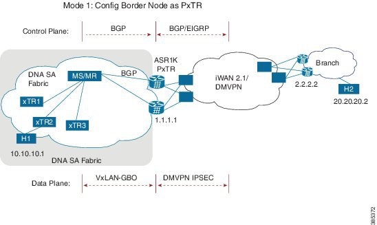
Figure 1. Border Node as
LISP PxTR
Control Plane Connectivity
Campus-to-Branches direction:
xTR will register its direct
attached host to MS/MR through LISP map-register.
There will be per-VRF BGP
sessions between MS/MR and PxTR, MS/MR will advertise LISP routes to PxTR
PxTR will re-originate those
routes to WAN through EIGRP or BGP.
Branches-to-Campus direction:
Branch routes will
advertise its routes to border nodes of campus through EIGRP or BGP.
Border nodes (PxTR) will not
advertise routes to LISP MS/MR.
On XTR, configure “ipv4
use-petr <rloc of PxTR> ”
Packet Flow with Control Plan Interworking
H1 to H2: SIP:10.10.10.1, DIP: 20.20.20.2
Assuming xTR2 is the default
gateway for H1 (it might not be the access switch, but the distribution switch
instead). H1 sends the IP packet to xTR2 after it resolves the ARP entry for
gateway MAC.
On xTR2, the IPv4 use-petr
2.2.2.2 is configured.
On xTR2, a MAP request is
initiated to MAP request, to resolve 20.20.20.2
A negative MAP reply is sent
from MS/MR to xTR2.
xTR2 encapsulation with LISP
head and sends to LISP PxTR 1.1.1.1
Branch router 2.2.2.2
advertises 20.20.20/24 routes to border node 1.1.1.1 using WAN protocol
BGP/EIGRP.
PxTR send the packet to
remote branch router 2.2.2.2 through iWAN/DMVPN.
H2 to H1: SIP: 20.20.20.2, DIP: 10.10.10.1
xTR2 register 10.10.10.1 to
MS/MS through LISP MAP-register.
MS/MR advertise this route
to PxTR 1.1.1.1
PxTR re-originates route to
branch route 2.2.2.2
H2 sends the packets to
branch router 2.2.2.2
Branch router 2.2.2.2
forwards the packets to PxTR 1.1.1.1
PxTR sends MAP-request to
resolve 10.10.10.1, and the MAP-reply is from xTR2.
PxTR sends LISP packets to
xTR2 and then to H1.
Configuring Border
Node as LISP xTR
Border node can be
configured as xTR for the fabric.
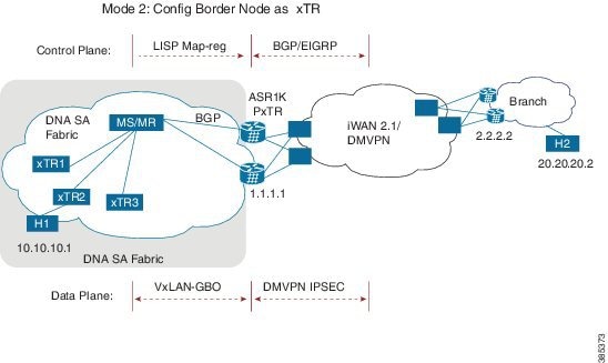
Figure 2. Border Node as LISP
xTR
Control Plane
Connectivity
Campus-to-Branches
direction--For each subnet of fabric, you must manually configure a static
route to null0 on ASR1K xTR. Example: ip route vrf vrf1 10.10.10.1
255.255.255.0 Null0 tag 110 ASR1K xTR (1.1.1.1) will advertise this static
route to remote branches (2.2.2.2) through BGP or EIGRP.
Branches-to-Campus
direction--Remote Branch (2.2.2.2) will advertise routes 20.20.20.2 to ASR1K
xTR (1.1.1.1) through BGP or EIGRP. On ASR1K xTR, configure “ipv4 route-import
database bgp 100 …” under LISP EID table to import BGP/EIGRP as LISP EID table.
ASR1K xTR 2.2.2.2 will initiate MAP-register to register the EID learnt from
BGP.
Packet Flow with Control
Plan Interworking
H1 to H2:
SIP:10.10.10.1, DIP: 20.20.20.2
Branch route 2.2.2.2
advertises routes 20.20.20.0/24 to LISP xTR 1.1.1.1 through BGP/EIGRP.
LISP xTR 1.1.1.1 will
import 20.20.20.0/24 into local EID table.
LISP xTR 1.1.1.1 sends
MAP-register to MS/MR to register 20.20.20.0/24 as its local EID
H1 sends IP packets to xTR2
after it resolves the MAC address of xTR2.
xTR2 sends map-request to
resolve the device for 20.20.20.2 and the RLOC is 1.1.1.1
xTR2 sends VxLAN
encapsulated packets to 1.1.1.1
RLOC 1.1.1.1 terminates
VxLAN and forwards the packets to 2.2.2.2.
H2 to H1: SIP:
20.20.20.2, DIP: 10.10.10.1
Static route of
10.10.10.1/24 is configured on xTR 1.1.1.1 and it points to null0
xTR advertises this route
to branch 2.2.2.2
H2 sends packets to branch
router 2.2.2.2
Branch router forwards the
packets to LISP xTR 1.1.1.1
Branch router 2.2.2.2
forwards the packets to PxTR 1.1.1.1
On LISP xTR 1.1.1.1,
10.10.10.1/24 is pointed to null0, which will trigger LISP routing; it will
send MAP-request to resolve the RLOC for 10.10.10.1.
LISP xTR 1.1.1.1 sends
VxLAN encapsulated packets to xTR2.
Security Group Tag
(SGT) Propagation
Besides the control
plane and data plane connectivity, the SGT tag must be carried over from the
campus fabric to WAN and vice-versa, so that SGT tag based policy will be
enforced end-to-end across campus and branches. This function has dependence on
WAN; if the WAN cannot carry the SGT tag, the tag will be lost.
vrf definition vrf1
 rd 1:1
 !
 address-family ipv4
  route-target export 1:1
  route-target import 1:1
 exit-address-family
!
vrf definition vrf2
 rd 1:2
 !
 address-family ipv4
 exit-address-family
 !
 interface Loopback0
 ip address 2.2.2.2 255.255.255.255
 !
 interface Loopback1
  vrf forwarding vrf1
  ip address 6.6.6.6 255.255.255.255
  !
  interface Tunnel200
  description “iWAN tunnel to remote branch”
   vrf forwarding vrf1
   ip address 150.0.0.2 255.255.255.0
   tunnel source GigabitEthernet2
   tunnel destination 17.0.0.1
   tunnel key 200
 !
 interface GigabitEthernet2
  ip address 17.0.0.2 255.255.255.0
  !
 interface GigabitEthernet3
  no ip address
  !
 interface GigabitEthernet3.6
  encapsulation dot1Q 6
  ip address 13.0.0.2 255.255.255.0
  ip ospf 1 area 0
  !
 interface GigabitEthernet3.7
  encapsulation dot1Q 7
  ip address 13.0.1.2 255.255.255.0
  ip ospf 1 area 0
  !
 interface GigabitEthernet4
  ip address 15.0.0.1 255.255.255.0
  ip ospf 1 area 0
  !
 router lisp
  encapsulation vxlan
  locator-set set1
  13.0.0.2 priority 1 weight 1
  13.0.1.2 priority 1 weight 1
 exit
 !
 eid-table default instance-id 0
  database-mapping 2.2.2.2/32 locator-set set1
  exit
  !
 eid-table vrf vrf1 instance-id 1
  database-mapping 6.6.6.6/32 locator-set set1
  ipv4 route-import database bgp 100 route-map match_com locator-set set1
  exit
  !
 eid-table vrf vrf2 instance-id 2
  database-mapping 6.6.6.6/32 locator-set set1
  exit
  !
 ipv4 sgt    //enable SGT function for SGT tag propagation//
  exit
 !
ipv4 use-petr 15.0.0.2
ipv4 itr map-resolver 14.0.0.1
ipv4 itr
ipv4 etr map-server 14.0.0.1 key cisco
ipv4 etr
exit
!
router ospf 1
!
router bgp 100
 bgp log-neighbor-changes
!
address-family ipv4 vrf vrf1
 redistribute static route-map tag_110
 neighbor 150.0.0.1 remote-as 100
 neighbor 150.0.0.1 activate
 neighbor 150.0.0.1 send-community both
 exit-address-family

ip bgp-community new-format
ip community-list 10 permit 200:1
ip route vrf vrf1 5.5.5.5 255.255.255.255 Null0 tag 110
!
route-map tag_110 permit 10
 match tag 110
!
route-map match_com permit 10
 match community 10
!
Feature
Information for DNA SA Border Node Support
The following table provides release information about the feature or features described in this module. This table lists
only the software release that introduced support for a given feature in a given software release train. Unless noted otherwise,
subsequent releases of that software release train also support that feature.
Use Cisco Feature Navigator to find information about platform support and Cisco software image support. To access Cisco
Feature Navigator, go to www.cisco.com/go/cfn. An account on Cisco.com is not required.
Table 1. Feature
Information for DNA SA Border Node Support
Feature Name
Releases
Feature
Information
DNA SA
Border Node Support
Cisco IOS XE Everest 16.4.1 Release
From Cisco
IOS XE Everest 16.4.1 release, ASR 1000/ISR 4000 platforms can be supported as
the border node of DNA SA fabric, handing off the enterprise campus fabric to
iWAN, providing IP connectivity across campus and branches.

 Feedback