- Table of Contents
- Preface
- Overview
- Networking with the Content Switching Module
- Getting Started
- Configuring VLANs
- Configuring Real Servers and Server Farms
- Configuring Virtual Servers, Maps and Policies
- Configuring Redundant Connections
- Configuring Additional Features and Options
- Configuring Health Monitoring
- Configuring CSM Scripts
- Configuring Firewall Load Balancing
- Configuration Examples
- System Messages
- CSM XML Document Type Definition
Catalyst 6500 Series Switch Content Switching Module Installation and Configuration Note, 3.2
Bias-Free Language
The documentation set for this product strives to use bias-free language. For the purposes of this documentation set, bias-free is defined as language that does not imply discrimination based on age, disability, gender, racial identity, ethnic identity, sexual orientation, socioeconomic status, and intersectionality. Exceptions may be present in the documentation due to language that is hardcoded in the user interfaces of the product software, language used based on RFP documentation, or language that is used by a referenced third-party product. Learn more about how Cisco is using Inclusive Language.
- Updated:
- May 4, 2007
Chapter: Configuring Additional Features and Options
Configuring Additional Features and Options
This chapter describes how to configure content switching and contains these sections:
•![]() Configuring Route Health Injection
Configuring Route Health Injection
•![]() Configuring Persistent Connections
Configuring Persistent Connections
•![]() Configuring Global Server Load Balancing
Configuring Global Server Load Balancing
•![]() Configuring Network Management
Configuring Network Management
Configuring Sticky Groups
Configuring a sticky group involves configuring the attributes of that group and associating it with a policy. Sticky time specifies the period of time that the sticky information is kept. The default sticky time value is 1440 minutes (24 hours).
To configure sticky groups, perform this task:
|
|
|
|---|---|
Router(config-module-csm)# sticky sticky-group-id {netmask netmask | cookie name | ssl} [address [source | destination | both]][timeout sticky-time] |
Ensures that connections from the same client matching the same policy use the same real server1 . |
1 The no form of this command restores the defaults. |
This example shows how to configure a sticky group and associate it with a policy:
Router(config-module-csm)# sticky 1 cookie foo timeout 100
Router(config-module-csm)# serverfarm pl_stick
Router(config-slb-sfarm)# real 10.8.0.18
Router(config-slb-real)# inservice
Router(config-slb-sfarm)# real 10.8.0.19
Router(config-slb-real)# inservice
Router(config-slb-real)# exit
Router(config-slb-sfarm)# exit
Router(config-module-csm)# policy policy_sticky_ck
Router(config-slb-policy)# serverfarm pl_stick
Router(config-slb-policy)# sticky-group 1
Router(config-slb-policy)# exit
Router(config-module-csm)# vserver vs_sticky_ck
Router(config-slb-vserver)# virtual 10.8.0.125 tcp 90
Router(config-slb-vserver)# slb-policy policy_sticky_ck
Router(config-slb-vserver)# inservice
Router(config-slb-vserver)# exit
Configuring Route Health Injection
These sections describe how to configure route health injection (RHI):
•![]() Configuring RHI for Virtual Servers
Configuring RHI for Virtual Servers
Understanding RHI
These sections describe the RHI:
•![]() Routing to VIP Addresses Without RHI
Routing to VIP Addresses Without RHI
•![]() Routing to VIP Addresses with RHI
Routing to VIP Addresses with RHI
•![]() Understanding How the CSM Determines VIP Availability
Understanding How the CSM Determines VIP Availability
•![]() Understanding Propagation of VIP Availability Information
Understanding Propagation of VIP Availability Information
RHI Overview
RHI allows the CSM to advertise the availability of a VIP address throughout the network. Multiple CSM devices with identical VIP addresses and services can exist throughout the network. One CSM can override the server load-balancing services over the other devices if the services are no longer available on the other devices. One CSM also can provide the services because it is logically closer to the client systems than other server load-balancing devices.

Note ![]() RHI is restricted to intranets because the CSM advertises the VIP address as a host route and most routers do not propagate the host-route information to the Internet.
RHI is restricted to intranets because the CSM advertises the VIP address as a host route and most routers do not propagate the host-route information to the Internet.
To enable RHI, configure the CSM to do the following:
•![]() Probe real servers and identify available virtual servers and VIP addresses
Probe real servers and identify available virtual servers and VIP addresses
•![]() Advertise accurate VIP address availability information to the MSFC whenever a change occurs
Advertise accurate VIP address availability information to the MSFC whenever a change occurs
Note ![]() On power-up with RHI enabled, the CSM sends a message to the MSFC as each VIP address becomes available.
On power-up with RHI enabled, the CSM sends a message to the MSFC as each VIP address becomes available.
The MSFC periodically propagates the VIP address availability information that RHI provides.
Note ![]() RHI is normally restricted to intranets; for security reasons, most routers do not propagate host-route information to the Internet.
RHI is normally restricted to intranets; for security reasons, most routers do not propagate host-route information to the Internet.
Routing to VIP Addresses Without RHI
Without RHI, traffic reaches the VIP address by following a route to the client VLAN to which the VIP address belongs. When the CSM powers on, the MSFC creates routes to client VLANs in its routing table and shares this route information with other routers. To reach the VIP, the client systems rely on the router to send the requests to the network subnet address where the individual VIP address lives.
If the subnet or segment is reachable but the virtual servers on the CSM at this location are not operating, the requests fail. Other CSM devices can be at different locations. However, the routers only send the requests based on the logical distance to the subnet.
Without RHI, traffic is sent to the VIP address without any verification that the VIP address is available. The real servers attached to the VIP might not be active.
Note ![]() By default, the CSM will not advertise the configured VIP addresses.
By default, the CSM will not advertise the configured VIP addresses.
Routing to VIP Addresses with RHI
With RHI, the CSM sends advertisements to the MSFC when VIP addresses become available and withdraws advertisements for VIP addresses that are no longer available. The router looks in the routing table to find the path information it needs to send the request from the client to the VIP address. When the RHI feature is turned on, the advertised VIP address information is the most specific match. The request for the client is sent through the path where it reaches the CSM with active VIP services.
When multiple instances of a VIP address exist, a client router receives the information it needs (availability and hop count) for each instance of a VIP address, allowing it to determine the best available route to that VIP address. The router chooses the path where the CSM is logically closer to the client system.
Note ![]() With RHI, you must also configure probes because the CSM determines if it can reach a given VIP address by probing all the real servers that serve its content. After determining if it can reach a VIP address, the CSM shares this availability information with the MSFC. The MSFC, in turn, propagates this VIP availability information to the rest of the intranet.
With RHI, you must also configure probes because the CSM determines if it can reach a given VIP address by probing all the real servers that serve its content. After determining if it can reach a VIP address, the CSM shares this availability information with the MSFC. The MSFC, in turn, propagates this VIP availability information to the rest of the intranet.
Understanding How the CSM Determines VIP Availability
For the CSM to determine if a VIP is available, you must configure a probe (HTTP, ICMP, Telnet, TCP, FTP, SMTP, or DNS) and associate it with a server farm. When probes are configured, the CSM performs these checks:
•![]() Probes all real servers on all server farms configured for probing
Probes all real servers on all server farms configured for probing
•![]() Identifies server farms that are reachable (have at least one reachable real server)
Identifies server farms that are reachable (have at least one reachable real server)
•![]() Identifies virtual servers that are reachable (have at least one reachable server farm)
Identifies virtual servers that are reachable (have at least one reachable server farm)
•![]() Identifies VIPs that are reachable (have at least one reachable virtual server)
Identifies VIPs that are reachable (have at least one reachable virtual server)
Understanding Propagation of VIP Availability Information
With RHI, the CSM sends advertise messages to the MSFC containing the available VIP addresses. The MSFC adds an entry in its routing table for each VIP address it receives from the CSM. The routing protocol running on the MSFC sends routing table updates to other routers. When a VIP address becomes unavailable, its route is no longer advertised, the entry times out, and the routing protocol propagates the change.
Note ![]() For RHI to work on the CSM, the MSFC in the chassis in which the CSM resides must run Cisco IOS Release 12.1.7(E) or later and must be configured as the client-side router.
For RHI to work on the CSM, the MSFC in the chassis in which the CSM resides must run Cisco IOS Release 12.1.7(E) or later and must be configured as the client-side router.
Configuring RHI for Virtual Servers
To configure RHI for the virtual servers, follow these steps:
Step 1 ![]() Verify that you have configured VLANs. (See the Chapter 4, "Configuring VLANs".)
Verify that you have configured VLANs. (See the Chapter 4, "Configuring VLANs".)
Step 2 ![]() Associate the probe with a server farm. (See the "Configuring Probes for Health Monitoring" section on page 9-1.)
Associate the probe with a server farm. (See the "Configuring Probes for Health Monitoring" section on page 9-1.)
Step 3 ![]() Configure the CSM to probe real servers. (See the "Configuring Probes for Health Monitoring" section on page 9-1.)
Configure the CSM to probe real servers. (See the "Configuring Probes for Health Monitoring" section on page 9-1.)
Step 4 ![]() Enter the advertise active SLB virtual server command to enable RHI for each virtual server:
Enter the advertise active SLB virtual server command to enable RHI for each virtual server:
Router(config-module-csm)# vserver virtual_server_name
Router(config-slb-vserver)# advertise active
This example shows how to enable RHI for the virtual server named vserver1:
Router(config-module-csm)# vserver vserver1
Router(config-slb-vserver)# advertise active
Environmental Variables
This example shows how to enable the environmental variables configuration:
Router(config-module-csm)# variable name string
You can get the current set of variables by running the show module csm slot variable [detail] command. For example:
Router# show mod csm 5 variable
variable value
----------------------------------------------------------------
ARP_INTERVAL 300
ARP_LEARNED_INTERVAL 14400
ARP_GRATUITOUS_INTERVAL 15
ARP_RATE 10
ARP_RETRIES 3
ARP_LEARN_MODE 1
ARP_REPLY_FOR_NO_INSERVICE_VIP 0
ADVERTISE_RHI_FREQ 10
AGGREGATE_BACKUP_SF_STATE_TO_VS 0
DEST_UNREACHABLE_MASK 0xffff
FT_FLOW_REFRESH_INT 60
GSLB_LICENSE_KEY (no valid license)
HTTP_CASE_SENSITIVE_MATCHING 1
MAX_PARSE_LEN_MULTIPLIER 1
NAT_CLIENT_HASH_SOURCE_PORT 0
ROUTE_UNKNOWN_FLOW_PKTS 0
NO_RESET_UNIDIRECTIONAL_FLOWS 0
SYN_COOKIE_INTERVAL 3
SYN_COOKIE_THRESHOLD 5000
TCP_MSS_OPTION 1460
TCP_WND_SIZE_OPTION 8192
VSERVER_ICMP_ALWAYS_RESPOND false
XML_CONFIG_AUTH_TYPE Basic
Cat6k-2#
Cat6k-2#
Cat6k-2#show mod csm 5 variable detail
Name:ARP_INTERVAL Rights:RW
Value:300
Default:300
Valid values:Integer (15 to 31536000)
Description:
Time (in seconds) between ARPs for configured hosts
Name:ARP_LEARNED_INTERVAL Rights:RW
Value:14400
Default:14400
Valid values:Integer (60 to 31536000)
Description:
Time (in seconds) between ARPs for learned hosts
Name:ARP_GRATUITOUS_INTERVAL Rights:RW
Value:15
Default:15
Valid values:Integer (10 to 31536000)
Description:
Time (in seconds) between gratuitous ARPs
Name:ARP_RATE Rights:RW
Value:10
Default:10
Valid values:Integer (1 to 60)
Description:
Seconds between ARP retries
Name:ARP_RETRIES Rights:RW
Value:3
Default:3
Valid values:Integer (2 to 15)
Description:
Count of ARP attempts before flagging a host as down
Name:ARP_LEARN_MODE Rights:RW
Value:1
Default:1
Valid values:Integer (0 to 1)
Description:
Indicates whether CSM learns MAC address on responses only (0) or all traffic (1)
Name:ARP_REPLY_FOR_NO_INSERVICE_VIP Rights:RW
Value:0
Default:0
Valid values:Integer (0 to 1)
Description:
Whether the CSM would reply to ARP for out-of-service vserver
Name:ADVERTISE_RHI_FREQ Rights:RW
Value:10
Default:10
Valid values:Integer (1 to 65535)
Description:
The frequency in second(s) the CSM will check for RHI updates
Name:AGGREGATE_BACKUP_SF_STATE_TO_VS Rights:RW
Value:0
Default:0
Valid values:Integer (0 to 1)
Description:
Whether to include the operational state of a backup serverfarm into the state of a
virtual server
Name:DEST_UNREACHABLE_MASK Rights:RW
Value:0xffff
Default:65535
Valid values:Integer (0 to 65535)
Description:
Bitmask defining which ICMP destination unreachable codes are to be forwarded
Name:FT_FLOW_REFRESH_INT Rights:RW
Value:60
Default:60
Valid values:Integer (1 to 65535)
Description:
FT slowpath flow refresh interval in seconds
Name:GSLB_LICENSE_KEY Rights:RW
Value:(no valid license)
Default:(no valid license)
Valid values:String (1 to 63 chars)
Description:
License key string to enable GSLB feature
Name:HTTP_CASE_SENSITIVE_MATCHING Rights:RW
Value:1
Default:1
Valid values:Integer (0 to 1)
Description:
Whether the URL (Cookie, Header) matching and sticky to be case sensitive
Name:MAX_PARSE_LEN_MULTIPLIER Rights:RW
Value:1
Default:1
Valid values:Integer (1 to 16)
Description:
Multiply the configured max-parse-len by this amount
Name:NAT_CLIENT_HASH_SOURCE_PORT Rights:RW
Value:0
Default:0
Valid values:Integer (0 to 1)
Description:
Whether to use the source port to pick client NAT IP address
Name:ROUTE_UNKNOWN_FLOW_PKTS Rights:RW
Value:0
Default:0
Valid values:Integer (0 to 1)
Description:
Whether to route non-SYN packets that do not matched any existing flows
Name:NO_RESET_UNIDIRECTIONAL_FLOWS Rights:RW
Value:0
Default:0
Valid values:Integer (0 to 1)
Description:
If set, unidirectional flows will not be reset when timed out
Name:SYN_COOKIE_INTERVAL Rights:RW
Value:3
Default:3
Valid values:Integer (1 to 60)
Description:
The interval, in seconds, at which a new syn-cookie key is generated
Name:SYN_COOKIE_THRESHOLD Rights:RW
Value:5000
Default:5000
Valid values:Integer (0 to 1048576)
Description:
The threshold (in number of pending sessions) at which syn-cookie is engaged
Name:TCP_MSS_OPTION Rights:RW
Value:1460
Default:1460
Valid values:Integer (1 to 65535)
Description:
Maximum Segment Size (MSS) value sent by CSM for L7 processing
Name:TCP_WND_SIZE_OPTION Rights:RW
Value:8192
Default:8192
Valid values:Integer (1 to 65535)
Description:
Window Size value sent by CSM for L7 processing
Name:VSERVER_ICMP_ALWAYS_RESPOND Rights:RW
Value:false
Default:false
Valid values:String (1 to 5 chars)
Description:
If "true" respond to ICMP probes regardless of vserver state
Name:XML_CONFIG_AUTH_TYPE Rights:RW
Value:Basic
Default:Basic
Valid values:String (5 to 6 chars)
Description:
HTTP authentication type for xml-config:Basic or Digest
Configuring Persistent Connections
The CSM allows HTTP connections to be switched based on a URL, cookies, or other fields contained in the HTTP header. Persistent connection support in the CSM allows for each successive HTTP request in a persistent connection to be switched independently. As a new HTTP request arrives, it may be switched to the same server as the prior request, it may be switched to a different server, or it may be reset to the client preventing that request from being completed.
In software release 2.1(1), the CSM supports HTTP 1.1 persistence. This feature allows browsers to send multiple HTTP requests on a single persistent connection. After a persistent connection is established, the server keeps the connection open for a configurable interval, anticipating that it may receive more requests from the same client. Persistent connections eliminate the overhead involved in establishing a new TCP connection for each request.
HTTP 1.1 persistence is enabled by default on all virtual servers configured with Layer 7 policies. To disable persistent connections, enter the no persistent rebalance command. To enable persistent connection, enter the persistent rebalance command.
This example shows how to configure persistent connection:
Router# configure terminal
Enter configuration commands, one per line. End with
CNTL/Z.
Router(config)# mod csm 2
!!! configuring serverfarm
Router(config-module-csm)# serverfarm sf3
Router(config-slb-sfarm)# real 10.1.0.105
Router(config-slb-real)# inservice
!!! configuring vserver
Router(config-slb-real)# vserver vs3
Router(config-slb-vserver)# virtual 10.1.0.83 tcp 80
Router(config-slb-vserver)# persistent rebalance
Router(config-slb-vserver)# serverfarm sf3
Router(config-slb-vserver)#
inservice
Router(config-slb-vserver)# end
Configuring Global Server Load Balancing
This section contains the Content Switching Module (CSM) global server load balancing (GSLB) advanced feature set option and instructions for its use. You should review the terms of the Software License Agreement carefully before using the advanced feature set option.
Note ![]() By downloading or installing the software, you are consenting to be bound by the license agreement. If you do not agree to all of the terms of this license, then do not download, install, or use the software.
By downloading or installing the software, you are consenting to be bound by the license agreement. If you do not agree to all of the terms of this license, then do not download, install, or use the software.
Using the GSLB Advanced Feature Set Option
To enable GSLB, perform this task in privileged mode:
|
|
|
|---|---|
Router# config t Router(config)# mod csm 5 |
Enters the configuration mode, and enters CSM configuration mode for the specific CSM (for example, module 5, as used here). |
Router(config-module-csm)# variable name value |
Enables GSLB by using the name and value provided as follows: |
Router(config-module-csm)# exit Router (config)# write mem |
Exits CSM module configuration mode, and save the configuration changes. |
Router#:hw-module slot number reset |
Reboots your CSM to activate changes. |
1 GSLB requires a separately purchased license. To purchase your GSLB license, contact your Cisco representative. |
Configuring GSLB
Global Server Load Balancing (GSLB) performs load balancing between multiple, dispersed hosting sites by directing client connections through DNS to different server farms and real servers based on load availability. GSLB is performed using access lists, maps, server farms, and load balancing algorithms. Table 8-1 gives an overview of what is required for a GSLB configuration on the CSM.
Figure 8-1 shows a basic configuration for GSLB.
Figure 8-1 Global Server Load Balancing Configuration
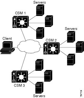
In this configuration illustration, the following guidelines apply to the configuration task and example:
•![]() CSM 1 does both GSLB and SLB, while CSM 2 and CSM 3 only do SLB.
CSM 1 does both GSLB and SLB, while CSM 2 and CSM 3 only do SLB.
•![]() CSM 1 has both a virtual server for SLB where the real servers in the server farm are the IP addresses of the local servers and a virtual server for GSLB.
CSM 1 has both a virtual server for SLB where the real servers in the server farm are the IP addresses of the local servers and a virtual server for GSLB.
•![]() The DNS policy uses a primary server farm where one of the real servers is local and the other two real servers are virtual servers configured on CSM 2 and CSM 3, respectively.
The DNS policy uses a primary server farm where one of the real servers is local and the other two real servers are virtual servers configured on CSM 2 and CSM 3, respectively.
•![]() Probes should be added for both the remote locations and the local real and virtual server.
Probes should be added for both the remote locations and the local real and virtual server.
•![]() DNS requests sent to a CSM 1 management IP address (a CSM 1 VLAN address or alias IP) will receive as a response one of the three real server IPs configured in the server farm GSLBFARM.
DNS requests sent to a CSM 1 management IP address (a CSM 1 VLAN address or alias IP) will receive as a response one of the three real server IPs configured in the server farm GSLBFARM.
To configure GSLB, perform these tasks:
This example shows how to configure GSLB:
On CSM1:
Router(config-module-csm)# serverfarm WEBFARM
Router(config-slb-sfarm)# predictor round-robin
Router(config-slb-sfarm)# real 3.5.5.5
Router(config-slb-real)# inservice
Router(config-slb-sfarm)# real 3.5.5.6
Router(config-slb-real)# inservice
Router(config-slb-real)# exit
Router(config-slb-sfarm)# exit
Router(config-module-csm)# vserver WEB
Router(config-slb-vserver)# virtual 10.10.10.10 tcp www
Router(config-slb-vserver)# serverfarm WEBFARM
Router(config-slb-vserver)#
inservice
Router(config-module-csm)# serverfarm GSLBSERVERFARM dns-vip
Router(config-slb-sfarm)# predictor round-robine
Router(config-slb-sfarm)# real 10.10.10.10
Router(config-slb-real)#
inservice
Router(config-slb-real)# exit
Router(config-slb-sfarm)# real 20.20.20.20
Router(config-slb-real)# inservice
Router(config-slb-real)# exit
Router(config-slb-sfarm)# real 30.30.30.30
Router(config-slb-real)# inservice
Router(config-slb-real)# exit
Router(config-module-csm)# map MAP1 dns
Router(config-dns-map)# match protocol dns domain foobar.com
Router(config-dns-map)# exit
Router(config-module-csm)# policy DNSPOLICY dns
Router(config-slb-policy)# dns map MAP1
Router(config-slb-policy)# serverfarm primary GSLBSERVERFARM ttl 20 responses 1
Router(config-slb-policy)# exit
Router(config-module-csm)# vserver DNSVSERVER dns
Router(config-slb-vserver)# dns-policy DNSPOLICY
Router(config-slb-vserver)#
inservice
On CSM 2:
Router(config-module-csm)# serverfarm WEBFARM
Router(config-slb-sfarm)# predictor round-robin
Router(config-slb-sfarm)# real 4.5.5.5
Router(config-slb-real)# inservice
Router(config-slb-sfarm)# real 4.5.5.6
Router(config-slb-real)# inservice
Router(config-slb-real)# exit
Router(config-slb-sfarm)# exit
Router(config-module-csm)# vserver WEB
Router(config-slb-vserver)# virtual 20.20.20.20 tcp www
Router(config-slb-vserver)#s erverfarm WEBFARM
Router(config-slb-vserver)#
inservice
On CSM 3:
Router(config-module-csm)# serverfarm WEBFARM
Router(config-slb-sfarm)# predictor round-robin
Router(config-slb-sfarm)# real 5.5.5.5
Router(config-slb-real)# inservice
Router(config-slb-sfarm)# real 5.5.5.6
Router(config-slb-real)# inservice
Router(config-slb-real)# exit
Router(config-slb-sfarm)# exit
Router(config-module-csm)# vserver WEB
Router(config-slb-vserver)# virtual 30.30.30.30 tcp www
Router(config-slb-vserver)# serverfarm WEBFARM
Router(config-slb-vserver)# inservice
Configuring Network Management
This section describes how to manage the CSM on the network and contains these sections.
•![]() Configuring SNMP Traps for Real Servers
Configuring SNMP Traps for Real Servers
•![]() Configuring the XML Interface
Configuring the XML Interface
Configuring SNMP Traps for Real Servers
When enabled, an SNMP trap is sent to an external management device each time a real server changes its state (for example, each time a server is taken in or out of service). The trap contains an object identifier (OID) that identifies it as a real-server trap.
Note ![]() The real server trap OID is 1.3.6.1.4.1.9.9.161.2
The real server trap OID is 1.3.6.1.4.1.9.9.161.2
The trap also contains a message describing the reason for the server state change.
Use the snmp-server enable traps slb ft command to either enable or disable fault-tolerant traps associated with the SLB function of the Catalyst 6500 switch. A fault-tolerant trap deals with the fault tolerance aspects of SLB. For example, when fault-tolerant traps are enabled and the SLB device detects a failure in its fault-tolerant peer, it sends an SNMP trap as it transitions from standby to active.
To configure SNMP traps for real servers, perform this task:
|
|
|
|
|---|---|---|
Step 1 |
Router (config)# snmp-server community public |
Defines a password-like community string sent with the notification operation. The example string is public. |
Step 2 |
Router (config)# snmp-server host host-addr |
Defines the IP address of an external network management device to which traps are sent. |
Step 3 |
Router (config)# snmp-server enable traps slb csrp |
Enables SNMP traps for real servers1 . |
1 The no form of this command disables the SNMP fault-tolerant traps feature. |
Configuring the XML Interface
In previous releases, the only method available for configuration of the CSM was the IOS command line interface. With XML, you can configure the CSM using a Document Type Definition or DTD. Refer to Appendix C, "CSM XML Document Type Definition" for a sample of an XML DTD.
These guidelines apply to XML for the CSM:
•![]() Up to five concurrent client connections are allowed.
Up to five concurrent client connections are allowed.
•![]() The XML configuration is independent of the IP SLB mode with the following exception: the csm_module slot='x' sense='no command does have the desired effect and generates an XML error.
The XML configuration is independent of the IP SLB mode with the following exception: the csm_module slot='x' sense='no command does have the desired effect and generates an XML error.
•![]() Pipelined HTTP posts are not supported.
Pipelined HTTP posts are not supported.
•![]() There is a 30-second timeout for all client communication.
There is a 30-second timeout for all client communication.
•![]() Bad client credentials cause a message to be sent to the IOS system log.
Bad client credentials cause a message to be sent to the IOS system log.
•![]() A single CSM can act as proxy for other CSM configuration by specifying a different slot attribute.
A single CSM can act as proxy for other CSM configuration by specifying a different slot attribute.
When you enable this feature, a network management device may connect to the CSM and send the new configurations to the device. The network management device sends configuration commands to the CSM using the standard HTTP protocol. The new configuration is applied by sending an XML document to the CSM in the data portion of an HTTP POST.
This example shows an HTTP conversation:
******** Client **************
POST /xml-config HTTP/1.1
Authorization: Basic VTpQ
Content-Length: 95
<?xml version="1.0"?>
<config><csm_module slot="4"><vserver name="FOO"/></csm_module></config>
******** Server **************
HTTP/1.1 200 OK
Content-Length: 21
<?xml version="1.0"?>
******** Client **************
POST /xml-config HTTP/1.1
Content-Length: 95
<?xml version="1.0"?>
<config><csm_module slot="4"><vserver name="FOO"/></csm_module></config>
******** Server **************
HTTP/1.1 401 Unauthorized
Connection: close
WWW-Authenticate: Basic realm=/xml-config
Table 8-2 lists the supported HTTP return codes:
The following HTTP headers are supported:
•![]() Content-Length (non-zero value required for all POSTs)
Content-Length (non-zero value required for all POSTs)
•![]() Connection (close value indicates that request should not be persistent)
Connection (close value indicates that request should not be persistent)
•![]() WWW-Authenticate (sent to client when credentials are required and missing)
WWW-Authenticate (sent to client when credentials are required and missing)
•![]() Authorization (sent from client to specify Basic credentials in base64 encoding)
Authorization (sent from client to specify Basic credentials in base64 encoding)
For the XML feature to operate, the network management system must connect to a CSM IP address, not a switch interface IP address.
Because the master copy of the configuration must be stored in Cisco IOS, as it is with the command line interface, when XML configuration requests are received by the CSM, these requests must be sent to the supervisor engine.
Note ![]() XML configuration allows a single CSM to act as proxy for all the CSMs in the same switch chassis. For example, an XML page with configuration for one CSM may be successfully posted through a different CSM in the same switch chassis.
XML configuration allows a single CSM to act as proxy for all the CSMs in the same switch chassis. For example, an XML page with configuration for one CSM may be successfully posted through a different CSM in the same switch chassis.
The Document Type Description (DTD), now publicly available, is the basis for XML configuration documents you create. (See Appendix C, "CSM XML Document Type Definition.") The XML documents are sent directly to the CSM in HTTP POST requests. To use XML, you must create a minimum configuration on the CSM in advance, using the Cisco IOS command line interface. Refer to the Catalyst 6500 Series Content Switching Module Command Reference for information on the xml-config command.
The response is an XML document mirroring the request with troublesome elements flagged with child-error elements, and with an error code and error string. You can specify which types of errors should be ignored by using an attribute of the root element in the XML document.
There will be an addition to the Cisco IOS command line interface for enabling XML configuration capabilities for a particular CSM interface. Along with the ability to enable and disable the TCP port, security options for client access lists and HTTP authentication are supported.
To configure XML on the CSM, perform this task:
This example shows how to run configure XML on the CSM:
Router(config-module-csm)# configure terminal
Router(config-module-csm)# m odule csm 4
Router(config-module-csm)# xml-config
Router(config-slb-xml)# port 23
Router(config-slb-xml)# vlan 200
Router(config-slb-xml)# client-group 60
Router(config-slb-xml)# credentials eric @#$#%%@
Router# show module csm 4 xml stats
When an untolerated XML error occurs, the HTTP response contains a 200 code. The portion of the original XML document with the error is returned with an error element that contains the error type and description.
This example shows an error response to a condition where a virtual server name is missing:
<?xml version="1.0"?>
<config>
<csm_module slot="4">
<vserver>
<error code="0x20">Missing attribute name in element
vserver</error>
</vserver>
</csm_module>
</config>
The error codes returned also correspond to the bits of the error tolerance attribute of the configuration element. The following are the returned XML error codes:
XML_ERR_INTERNAL = 0x0001,
XML_ERR_COMM_FAILURE = 0x0002,
XML_ERR_WELLFORMEDNESS = 0x0004,
XML_ERR_ATTR_UNRECOGNIZED = 0x0008,
XML_ERR_ATTR_INVALID = 0x0010,
XML_ERR_ATTR_MISSING = 0x0020,
XML_ERR_ELEM_UNRECOGNIZED = 0x0040,
XML_ERR_ELEM_INVALID = 0x0080,
XML_ERR_ELEM_MISSING = 0x0100,
XML_ERR_ELEM_CONTEXT = 0x0200,
XML_ERR_IOS_PARSER = 0x0400,
XML_ERR_IOS_MODULE_IN_USE = 0x0800,
XML_ERR_IOS_WRONG_MODULE = 0x1000,
XML_ERR_IOS_CONFIG = 0x2000
The default error_tolerance value is 0x48, which corresponds to ignoring unrecognized attributes and elements.
 Feedback