- Title and copyright: PA-E3 Serial Port Adapter Installation and Configuration
- Preface: PA-E3 Serial Port Adapter Installation and Configuration
- Overview: PA-E3 Serial Port Adapter Installation and Configuration
- Preparing to Install the PA-E3 Port Adapter
- Removing and Installing the PA-E3 Port Adapter
- Configuring the PA-E3 Port Adapter
PA-E3 Serial Port Adapter Installation and Configuration
Bias-Free Language
The documentation set for this product strives to use bias-free language. For the purposes of this documentation set, bias-free is defined as language that does not imply discrimination based on age, disability, gender, racial identity, ethnic identity, sexual orientation, socioeconomic status, and intersectionality. Exceptions may be present in the documentation due to language that is hardcoded in the user interfaces of the product software, language used based on RFP documentation, or language that is used by a referenced third-party product. Learn more about how Cisco is using Inclusive Language.
- Updated:
- September 14, 2007
Chapter: Overview: PA-E3 Serial Port Adapter Installation and Configuration
- Port Adapter Overview
- Features
- LEDs
- Cables, Connectors, and Pinouts
- Management Information Base
- Port Adapter Slot Locations on the Supported Platforms
- Catalyst RSM/VIP2 Slot Numbering
- Catalyst 6000 Family FlexWAN Module Slot Numbering
- Cisco 7100 Series Routers Slot Numbering
- Cisco 7200 Series Routers and Cisco 7200 VXR Routers Slot Numbering
- Cisco uBR7200 Series Router Slot Numbering
- Cisco 7201 Router Slot Numbering
- Cisco 7301 Router Slot Numbering
- Cisco 7304 PCI Port Adapter Carrier Card Slot Numbering
- Cisco 7401ASR Router Slot Numbering
- Cisco 7000 Series Routers and Cisco 7500 Series Routers VIP Slot Numbering
- Identifying Interface Addresses
- Catalyst RSM/VIP2 Interface Addresses
- Catalyst 6000 Family FlexWAN Module Interface Addresses
- Cisco 7100 Series Routers Interface Addresses
- Cisco 7200 Series Routers and Cisco 7200 VXR Routers Interface Addresses
- Cisco uBR7200 Series Routers Interface Addresses
- Cisco 7201 Router Interface Addresses
- Cisco 7301 Router Interface Addresses
- Cisco 7304 PCI Port Adapter Carrier Card Interface Addresses
- Cisco 7401ASR Router Interface Addresses
- Cisco 7000 Series Routers and Cisco 7500 Series Routers VIP Interface Addresses
- Interoperability Guidelines for PA-E3 DSUs
Overview
This chapter describes the one-port PA-E3 and two-port PA-2E3 serial port adapters. This chapter contains the following sections:
•![]() LEDs
LEDs
•![]() Cables, Connectors, and Pinouts
Cables, Connectors, and Pinouts
•![]() Port Adapter Slot Locations on the Supported Platforms
Port Adapter Slot Locations on the Supported Platforms
•![]() Identifying Interface Addresses
Identifying Interface Addresses
•![]() Interoperability Guidelines for PA-E3 DSUs
Interoperability Guidelines for PA-E3 DSUs
Port Adapter Overview
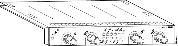
The PA-E3 is a single-width, one-port or two-port port adapter that integrates data service unit (DSU) functionality into the Cisco router (see Figure 1-1 and Figure 1-2). The port adapters provides one or two high-speed serial E3 interfaces.

Note ![]() Port adapters have a handle attached, but this handle is occasionally not shown in figures in this publication to allow a full view of detail on the port adapter's faceplate.
Port adapters have a handle attached, but this handle is occasionally not shown in figures in this publication to allow a full view of detail on the port adapter's faceplate.
Figure 1-1 One-Port PA-E3 Serial Port Adapter
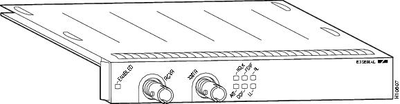
Figure 1-2 Two-Port PA-2E3 Serial Port Adapter
The one-port PA-E3 provides up to two network interfaces per Catalyst RSM/VIP2 for the Catalyst 5000 family switches, Catalyst 6000 family FlexWAN module in the Catalyst 6000 family switches, and VIP for Cisco 7000 series and Cisco 7500 series routers, and one high-speed interface on the Cisco 7100 series routers, Cisco 7200 series routers, Cisco 7200 VXR routers, Cisco uBR7200 series routers, the Cisco 7201 router, the Cisco 7301 router, the Cisco 7401ASR router, and the Cisco 7304 PCI Port Adapter Carrier Card in the Cisco 7304 router.
The two-port PA-2E3 provides up to four network interfaces per Catalyst RSM/VIP2 for the Catalyst 5000 family switches, Catalyst 6000 family FlexWAN module in the Catalyst 6000 family switches, and VIP for Cisco 7000 series and Cisco 7500 series routers, and two high-speed interfaces on the Cisco 7100 series routers, Cisco 7200 series routers, Cisco 7200 VXR routers, Cisco uBR7200 series routers, Cisco 7201 router, Cisco 7301 router, Cisco 7401ASR router, and Cisco 7304 PCI Port Adapter Carrier Card in the Cisco 7304 router.
Serial network interfaces reside on modular port adapters, which provide a direct connection between the high-speed bus in the router and the external networks. The PA-E3 provides a full-duplex synchronous serial E3 interface for transmitting and receiving data at rates of up to 34 megabits per second (Mbps).
The port adapters both supports both 16- and 32-bit cyclic redundancy checks (CRCs). The default is 16-bit CRCs; to enable 32-bit CRCs, you use a configuration command. For a description of the CRC function, see the "Configuring Cyclic Redundancy Checks" section on page 4-10.
Note ![]() The Catalyst RSM/VIP2, the Catalyst 6000 family FlexWAN module, the VIP, and the Cisco 7304 PCI Port Adapter Carrier Card support online insertion and removal (OIR), but individual port adapters do not. To replace port adapters, you must first remove the Catalyst RSM/VIP2, the Catalyst 6000 family FlexWAN module, the VIP, or the Cisco 7304 PCI Port Adapter Carrier Card from the chassis and then replace port adapters as required.
The Catalyst RSM/VIP2, the Catalyst 6000 family FlexWAN module, the VIP, and the Cisco 7304 PCI Port Adapter Carrier Card support online insertion and removal (OIR), but individual port adapters do not. To replace port adapters, you must first remove the Catalyst RSM/VIP2, the Catalyst 6000 family FlexWAN module, the VIP, or the Cisco 7304 PCI Port Adapter Carrier Card from the chassis and then replace port adapters as required.
OIR is supported for port adapters in the Cisco 7100 series routers, Cisco 7200 series routers, Cisco 7200 VXR routers, Cisco uBR7200 series routers, Cisco 7201 router, Cisco 7301 router, and Cisco 7401ASR router.
Features
The PA-E3 serial port adapter has the following features:
•![]() Single- or double-port E3 rate (34 Mbps) connectivity
Single- or double-port E3 rate (34 Mbps) connectivity
•![]() Full-duplex synchronous serial E3 interface
Full-duplex synchronous serial E3 interface
•![]() High-speed High-Level Data Link Control (HDLC) data
High-speed High-Level Data Link Control (HDLC) data
•![]() Integrated data service unit (DSU) functionality
Integrated data service unit (DSU) functionality
•![]() Support for 16- and 32-bit cyclic redundancy checks (CRCs)
Support for 16- and 32-bit cyclic redundancy checks (CRCs)
•![]() Support for G.751 framing or bypass framing
Support for G.751 framing or bypass framing
•![]() Support for ATM-DXI, Frame Relay, HDLC, Switched Multimegabit Data Service (SMDS), and PPP serial encapsulations
Support for ATM-DXI, Frame Relay, HDLC, Switched Multimegabit Data Service (SMDS), and PPP serial encapsulations
•![]() Support for national service bits
Support for national service bits
•![]() Support for E3 MIB (RFC 1407)
Support for E3 MIB (RFC 1407)
•![]() Support for remote and local loopback
Support for remote and local loopback
•![]() HDB3 line coding
HDB3 line coding
•![]() Scrambling and bandwidth reduction
Scrambling and bandwidth reduction
•![]() Online insertion and removal (OIR)
Online insertion and removal (OIR)
LEDs
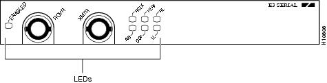
The one-port PA-E3 has one status LED and six uplink port status LEDs (RCLK, FERF, OOF, AIS, RL, and LL) for the serial E3 port. (See Figure 1-3.)
Figure 1-3 One-Port PA-E3 LEDs—Partial Front View Shown
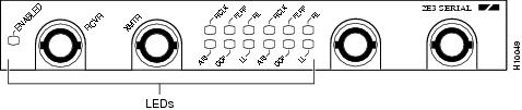
The two-port PA-2E3 has one status LED and six uplink port status LEDs (RCLK, FERF, OOF, AIS, RL, and LL) for each serial E3 port. (See Figure 1-4.)
Figure 1-4 Two-Port PA-2E3 LEDs—Partial Front View Shown
After system initialization, the ENABLED LED goes on, indicating that the port adapter has been enabled for operation.
The following conditions must be met before the PA-E3 is enabled:
•![]() The port adapter contains a valid microcode version that has been downloaded successfully.
The port adapter contains a valid microcode version that has been downloaded successfully.
•![]() The port adapter is correctly connected to and receiving power from the Catalyst RSM/VIP2 motherboard, the Catalyst 6000 family FlexWAN module, the VIP, or the Cisco 7304 PCI Port Adapter Carrier Card.
The port adapter is correctly connected to and receiving power from the Catalyst RSM/VIP2 motherboard, the Catalyst 6000 family FlexWAN module, the VIP, or the Cisco 7304 PCI Port Adapter Carrier Card.
•![]() The bus recognizes the port adapter.
The bus recognizes the port adapter.
If any of these conditions are not met, or if the initialization fails for other reasons, the ENABLED LED does not go on.
Table 1-1 describes the PA-E3 LEDs.
Cables, Connectors, and Pinouts
The serial interface cable for the PA-E3, which is a 75-ohm coaxial cable, is used to connect your router to a serial E3 network. Serial cables conform to EIA/TIA-612 and EIA/TIA-613 specifications. The serial ports on the PA-E3 are considered to be DTE devices.
On a single PA-E3, there are one or two serial E3 ports, each with two connectors (receive and transmit), where you connect the Cisco 75-ohm coaxial cable. The 75-ohm coaxial cable (Cisco part number CAB-ATM-DS3/E3) for the PA-E3 is available only from Cisco Systems; it is not available from outside commercial cable vendors.
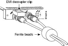
The Cisco E3 75-ohm coaxial cable, which comes with an attached ferrite sleeve (see Figure 1-5), is available only in 10-foot (3.05-meter) lengths. Line build-out is programmable for up to 450 feet of 734A or equivalent coaxial cable or up to 225 feet for 728A or equivalent coaxial cable.
Note ![]() For E3 (75-ohm) connections, you must have ferrite beads on the 75-ohm coaxial cable and EMI decoupling clips on the receive end of the cable (see Figure 1-5) if compliance with European certification standards for emission control is required (EN55022/CISPR22 Class B for radiated emission levels).
For E3 (75-ohm) connections, you must have ferrite beads on the 75-ohm coaxial cable and EMI decoupling clips on the receive end of the cable (see Figure 1-5) if compliance with European certification standards for emission control is required (EN55022/CISPR22 Class B for radiated emission levels).
Figure 1-5 PA-E3 Cables
You can test the DTE-to-DCE cable connection by using the loopback dte command. See the "Using loopback Commands" section on page 4-29 for more information.
Management Information Base
Management Information Base (MIB) attributes are readable and writable across the ILMI through use of SNMP.
The one-port PA-E3 supports MIB-II (RFC 1213) and the E3 interface MIB (RFC 1407).
The two-port PA-2E3 supports MIB-II (RFC 1213) and the E3 interface MIB (RFC 1407).
Port Adapter Slot Locations on the Supported Platforms
The following sections provide port adapter slot locations and related information:
•![]() Catalyst RSM/VIP2 Slot Numbering
Catalyst RSM/VIP2 Slot Numbering
•![]() Catalyst 6000 Family FlexWAN Module Slot Numbering
Catalyst 6000 Family FlexWAN Module Slot Numbering
•![]() Cisco 7100 Series Routers Slot Numbering
Cisco 7100 Series Routers Slot Numbering
•![]() Cisco 7200 Series Routers and Cisco 7200 VXR Routers Slot Numbering
Cisco 7200 Series Routers and Cisco 7200 VXR Routers Slot Numbering
•![]() Cisco uBR7200 Series Router Slot Numbering
Cisco uBR7200 Series Router Slot Numbering
•![]() Cisco 7201 Router Slot Numbering
Cisco 7201 Router Slot Numbering
•![]() Cisco 7301 Router Slot Numbering
Cisco 7301 Router Slot Numbering
•![]() Cisco 7304 PCI Port Adapter Carrier Card Slot Numbering
Cisco 7304 PCI Port Adapter Carrier Card Slot Numbering
•![]() Cisco 7401ASR Router Slot Numbering
Cisco 7401ASR Router Slot Numbering
•![]() Cisco 7000 Series Routers and Cisco 7500 Series Routers VIP Slot Numbering
Cisco 7000 Series Routers and Cisco 7500 Series Routers VIP Slot Numbering
Catalyst RSM/VIP2 Slot Numbering
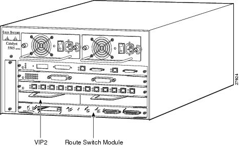
The Catalyst RSM/VIP2 can be installed in any slot in a Catalyst 5000 family switch except the top slots, which contain the supervisor engine modules. The Catalyst RSM/VIP2 does not use interface processor slot numbering; therefore, the slots in which it is installed are not numbered. The PA-E3 can be installed into either port adapter slot 0 or slot 1 on a Catalyst RSM/VIP2. Figure 1-6 shows a Catalyst RSM/VIP2 with two port adapters installed.
Note ![]() The Catalyst 5500 switch has 13 slots. Slot 1 is reserved for the supervisor engine module. If a redundant supervisor engine module is used, it would go in slot 2; otherwise, slot 2 can be used for other modules. Slot 13 is a dedicated slot, reserved for the ATM Switch Processor (ASP) module. Refer to the Catalyst 5000 Series Route Switch Module Installation and Configuration Note for any additional slot restrictions for the Catalyst RSM/VIP2.
The Catalyst 5500 switch has 13 slots. Slot 1 is reserved for the supervisor engine module. If a redundant supervisor engine module is used, it would go in slot 2; otherwise, slot 2 can be used for other modules. Slot 13 is a dedicated slot, reserved for the ATM Switch Processor (ASP) module. Refer to the Catalyst 5000 Series Route Switch Module Installation and Configuration Note for any additional slot restrictions for the Catalyst RSM/VIP2.
Figure 1-6 Catalyst 5000 Family Switch with Port Adapters Installed on Catalyst RSM/VIP2
Catalyst 6000 Family FlexWAN Module Slot Numbering
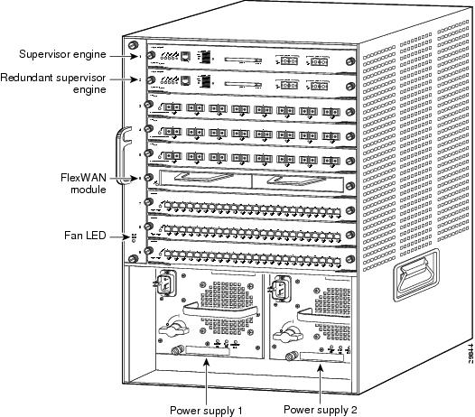
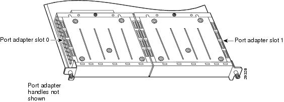
The Catalyst 6000 family FlexWAN module can be installed in any slot in a Catalyst 6000 family switch except slot 1, which is reserved for the supervisor engine. The PA-E3 can be installed into either port adapter bay 0 or bay 1 on a FlexWAN module. Figure 1-7 shows a FlexWAN module with two blank port adapters installed.
Note ![]() Slot 1 is reserved for the supervisor engine. If a redundant supervisor engine is used, it would go in slot 2; otherwise, slot 2 can be used for other modules.
Slot 1 is reserved for the supervisor engine. If a redundant supervisor engine is used, it would go in slot 2; otherwise, slot 2 can be used for other modules.
Figure 1-7 Catalyst 6000 Family Switch with Port Adapters Installed on FlexWAN Module
Cisco 7100 Series Routers Slot Numbering
Port adapters can be installed in port adapter slot 3 in Cisco 7120 series routers, and in port adapter slot 4 in Cisco 7140 series routers. Figure 1-8 shows the slot numbering on a Cisco 7120 series router. Figure 1-9 shows the slot numbering on a Cisco 7140 series router.
Figure 1-8 Port Adapter Slots in the Cisco 7120 Series Router
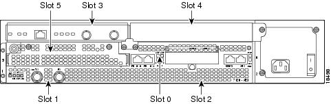
Figure 1-9 Port Adapter Slots in the Cisco 7140 Series Router
Cisco 7200 Series Routers and Cisco 7200 VXR Routers Slot Numbering
Cisco 7202 routers have two port adapter slots. The slots are numbered from left to right. You can place a port adapter in either of the slots (slot 1 or slot 2). The Cisco 7202 router is not shown.
Cisco 7204 routers and Cisco 7204VXR routers have four slots for port adapters, and one slot for an input/output (I/O) controller. The slots are numbered from the lower left to the upper right, beginning with slot 1 and continuing through slot 4. You can place a port adapter in any of the slots (slot 1 through slot 4). Slot 0 is always reserved for the I/O controller. The Cisco 7204 router and Cisco 7204VXR are not shown.
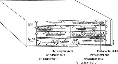
Cisco 7206 routers and Cisco 7206VXR routers (including the Cisco 7206 and Cisco 7206VXR routers as router shelves in a Cisco AS5800 Universal Access Server) have six slots for port adapters, and one slot for an input/output (I/O) controller. The slots are numbered from the lower left to the upper right, beginning with slot 1 and continuing through slot 6. You can place a port adapter in any of the six slots (slot 1 through slot 6). Slot 0 is always reserved for the I/O controller. Figure 1-10 shows the slot numbering on a Cisco 7206 router. The Cisco 7206VXR router is not shown.
Figure 1-10 Port Adapter Slots in the Cisco 7206 Router
Cisco uBR7200 Series Router Slot Numbering
The Cisco uBR7223 router has one port adapter slot (slot 1). Slot 0 is always reserved for the I/O controller—if present. The Cisco uBR7223 router is not shown.
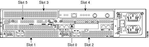
The Cisco uBR7246 router and Cisco uBR7246VXR router have two port adapter slots (slot1 and slot 2). Slot 0 is always reserved for the I/O controller—if present. Figure 1-11 shows the slot numbering of port adapters on a Cisco uBR7246 router or Cisco uBR7246VXR router.
Figure 1-11 Port Adapter Slots in the Cisco uBR7246 and Cisco uBR7246VXR Routers
Cisco 7201 Router Slot Numbering
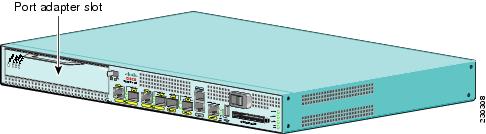
Figure 1-12 shows the front view of a Cisco 7201 router with a port adapter installed. There is only one port adapter slot (slot 1) in a Cisco 7201 router.
Figure 1-12 Port Adapter Slot in the Cisco 7201 Router
Cisco 7301 Router Slot Numbering
Figure 1-13 shows the front view of a Cisco 7301 router with a port adapter installed. There is only one port adapter slot (slot 1) in a Cisco 7301 router.
Figure 1-13 Port Adapter Slot in the Cisco 7301 Router

Cisco 7304 PCI Port Adapter Carrier Card Slot Numbering
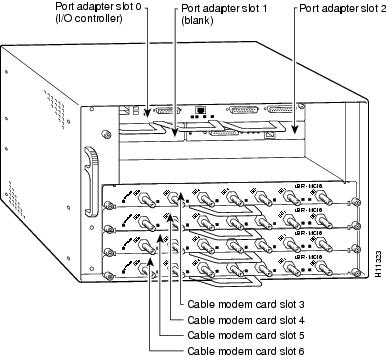
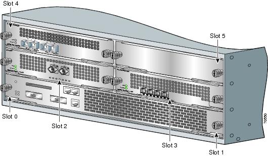
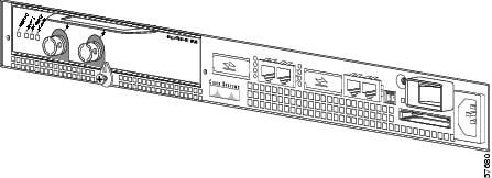
The Cisco 7304 PCI Port Adapter Carrier Card installs in Cisco 7304 router module slots 2 through 5. Figure 1-14 shows a Cisco 7304 PCI Port Adapter Carrier Card with a port adapter installed. The Cisco 7304 PCI Port Adapter Carrier Card accepts one single-width port adapter.
Figure 1-15 shows the module slot numbering on a Cisco 7304 router. The port adapter slot number is the same as the module slot number. Slot 0 and slot 1 are reserved for the NPE module or NSE module.
Figure 1-14 Cisco 7304 PCI Port Adapter Carrier Card—Port Adapter Installed
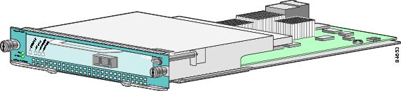
Figure 1-15 Module Slots on the Cisco 7304 Router
Cisco 7401ASR Router Slot Numbering
Figure 1-16 shows the front view of a Cisco 7401ASR router with a port adapter installed. There is only one port adapter slot (slot 1) in a Cisco 7401ASR router.
Figure 1-16 Port Adapter Slot in the Cisco 7401ASR Router
Cisco 7000 Series Routers and Cisco 7500 Series Routers VIP Slot Numbering
Port adapters are supported on the VIPs (versatile interface processors) used in Cisco 7000 series and Cisco 7500 series routers. In the Cisco 7010 router and Cisco 7505 router, the VIP motherboard is installed horizontally in the VIP slot. In the Cisco 7507 router and Cisco 7513 router, the VIP motherboard is installed vertically in the VIP slot. A port adapter can be installed in either bay (port adapter slot 0 or 1) on the VIP. The bays are numbered from left to right on the VIP. Figure 1-17 shows the slot numbering on a VIP.
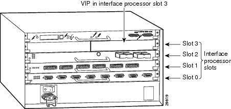
Figure 1-17 VIP Slot Locations
Cisco 7010 routers have three slots for port adapters, and two slots for Route Switch Processors (RSPs). The slots are numbered from bottom to top. You can place a port adapter in any of the VIP interface slots (slot 0 through 2). Slots 3 and 4 are always reserved for RSPs. The Cisco 7010 router is not shown.
Cisco 7505 routers have four slots for port adapters, and one slot for an RSP. The slots are numbered from bottom to top. You can place a port adapter in any of the VIP interface slots (slot 0 through 3). One slot is always reserved for the RSP. Figure 1-18 shows the slot numbering on a Cisco 7505 router.
Figure 1-18 VIP Slots in the Cisco 7505 Router
Cisco 7507 routers have five slots for port adapters, and two slots for RSPs. The slots are numbered from left to right. You can place a port adapter in any of the VIP interface slots (slot 0, 1, 4, 5, or 6). Slots 2 and 3 are always reserved for RSPs. The Cisco 7507 router is not shown.
Cisco 7513 routers have eleven slots for port adapters, and two slots for RSPs. The slots are numbered from left to right. You can place a port adapter in any of the VIP interface slots (slots 0 through 5, or slots 9 through 12). Slots 6 and 7 are always reserved for RSPs. The Cisco 7513 router is not shown.
Identifying Interface Addresses
This section describes how to identify interface addresses for the PA-E3 in supported platforms. Interface addresses specify the actual physical location of each interface on a router or switch.
Interfaces on the PA-E3 installed in a router maintain the same address regardless of whether other port adapters are installed or removed. However, when you move a port adapter to a different slot, the first number in the interface address changes to reflect the new port adapter slot number.
Interfaces on a PA-E3 installed in a VIP or FlexWAN module maintain the same address regardless of whether other interface processors or modules are installed or removed. However, when you move a VIP or FlexWAN module to a different slot, the interface processor or module slot number changes to reflect the new interface processor or module slot.
Note ![]() Interface ports are numbered from left to right starting with 0.
Interface ports are numbered from left to right starting with 0.
The following subsections describe the interface address formats for the supported platforms:
•![]() Catalyst RSM/VIP2 Interface Addresses
Catalyst RSM/VIP2 Interface Addresses
•![]() Catalyst 6000 Family FlexWAN Module Interface Addresses
Catalyst 6000 Family FlexWAN Module Interface Addresses
•![]() Cisco 7100 Series Routers Interface Addresses
Cisco 7100 Series Routers Interface Addresses
•![]() Cisco 7200 Series Routers and Cisco 7200 VXR Routers Interface Addresses
Cisco 7200 Series Routers and Cisco 7200 VXR Routers Interface Addresses
•![]() Cisco uBR7200 Series Routers Interface Addresses
Cisco uBR7200 Series Routers Interface Addresses
•![]() Cisco 7201 Router Interface Addresses
Cisco 7201 Router Interface Addresses
•![]() Cisco 7301 Router Interface Addresses
Cisco 7301 Router Interface Addresses
•![]() Cisco 7301 Router Interface Addresses
Cisco 7301 Router Interface Addresses
•![]() Cisco 7304 PCI Port Adapter Carrier Card Interface Addresses
Cisco 7304 PCI Port Adapter Carrier Card Interface Addresses
•![]() Cisco 7401ASR Router Interface Addresses
Cisco 7401ASR Router Interface Addresses
•![]() Cisco 7000 Series Routers and Cisco 7500 Series Routers VIP Interface Addresses
Cisco 7000 Series Routers and Cisco 7500 Series Routers VIP Interface Addresses
Table 1-2 summarizes the interface address formats for the supported platforms.
|
|
|
|
|
|---|---|---|---|
Catalyst RSM/VIP2 in |
Port-adapter-slot-number/interface-port-number |
Port adapter slot— 0 or 1 Interface port—0 or 1 |
0/1 |
Catalyst 6000 family FlexWAN module in Catalyst 6000 family switches |
Module-slot-number/port-adapter-bay-number/ |
Module slot —21 through 13 (depends on the number of slots in the switch) Port adapter bay— 0 or 1 Interface port—0 or 1 |
3/0/0 |
Cisco 7120 series router |
Port-adapter-slot-number/interface-port-number |
Port adapter slot—always 3 Interface port—0 or 1 |
3/1 |
Cisco 7140 series router |
Port-adapter-slot-number/interface-port-number |
Port adapter slot—always 4 Interface port—0 or 1 |
4/0 |
Cisco 7200 series routers and Cisco 7200 VXR routers |
Port-adapter-slot-number/interface-port-number |
Port adapter slot—1 through 6 (depends on the number of slots in the router)2 Interface port—0 |
1/0 |
Cisco uBR7223 router |
Port-adapter-slot-number/interface-port-number |
Port adapter slot—always 13 Interface port—0 or 1 |
1/0 |
Cisco uBR7246 router |
Port-adapter-slot-number/interface-port-number |
Port adapter slot— 1 or 23 Interface port—0 or 1 |
1/1 |
Cisco 7201 router |
Port-adapter-slot-number/interface-port-number |
Port adapter slot—always 1 Interface port—0 or 1 |
1/0 |
Cisco 7301 router |
Port-adapter-slot-number/interface-port-number |
Port adapter slot—always 1 Interface port—0 or 1 |
1/0 |
Cisco 7304 PCI Port Adapter Carrier Card in Cisco 7304 router |
Module-slot-number/interface-port-number |
Module slot—2 through 5 Interface port—0 or 1 |
3/0 |
Cisco 7401ASR router |
Port-adapter-slot-number/interface-port-number |
Port adapter slot—always 1 Interface port—0 or 1 |
1/0 |
VIP in Cisco 7000 series or Cisco 7500 series routers |
Interface-processor-slot-number/port-adapter-slot- |
Interface processor slot—0 through 12 (depends on the number of slots in the router) Port adapter slot—0 or 1 Interface port—0 or 1 |
3/1/0 |
1 Slot 1 is reserved for the supervisor engine. If a redundant supervisor engine is used, it must go in slot 2; otherwise, slot 2 can be used for other modules. 2 Port adapter slot 0 is reserved for the Fast Ethernet port on the I/O controller (if present). 3 Port adapter slot 0 is reserved for the Fast Ethernet port on the I/O controller (if present). |
Catalyst RSM/VIP2 Interface Addresses
In Catalyst 5000 family switches, the Catalyst RSM/VIP2 can be installed in any slot except the top slots, which contain the supervisor engine modules. The Catalyst RSM/VIP2 in a Catalyst 5000 family switch does not use interface processor slot numbering; therefore, the slots in which it is installed are not numbered. A port adapter can be installed into either port adapter slot 0 or slot 1 on a Catalyst RSM/VIP2. See Figure 1-6.
The interface address is composed of a two-part number in the format port-adapter-slot number/interface-port number. See Table 1-2. For example, if a single-port PA-E3 is installed in port adapter slot 1 of a Catalyst RSM/VIP2 in a Catalyst 5000 family switch, the interface address would be 1/0. If a dual-port PA-2E3 is installed in port adapter slot 1 of a Catalyst RSM/VIP2 in a Catalyst 5000 family switch, the interface addresses would be 1/0 and 1/1.
Catalyst 6000 Family FlexWAN Module Interface Addresses
In Catalyst 6000 family switches, the Catalyst 6000 family FlexWAN module can be installed in module slots 2 through 13 (depending on the number of slots in the router). Slot 1 is reserved for the supervisor engine. A port adapter can be installed into either port adapter bay 0 or bay 1 on a FlexWAN module. See Figure 1-7.
The interface address is composed of a three-part number in the format module-number/port-adapter-bay-number/interface-port-number. See Table 1-2.
The first number identifies the module slot of the chassis in which the FlexWAN module is installed (slot 2 through slot 3, 6, 9, or 13 depending on the number of slots in the chassis). These module slots are generally numbered from top to bottom, starting with 1.
The second number identifies the bay of the FlexWAN module in which the port adapter is installed (0 or 1). The bays are numbered from left to right on the FlexWAN module.
The third number identifies the physical port number on the port adapter. The PA-E3 is a single-port port adapter, therefore the port is always 0. The PA-2E3 is a dual-port port adapter, therefore the port can be 0 or 1.
For example, if a single-port PA-E3 is installed in a FlexWAN module in module slot 3, port adapter bay 0, then the interface address is 3/0/0 (module slot 3, port adapter bay 0, and interface 0). I f a dual-port PA-2E3 is installed in a FlexWAN module in module slot 3, port adapter bay 0, then the interface addresses are 3/0/0 and 3/0/1 (module slot 3, port adapter bay 0, and interfaces 0 and 1).
Note ![]() The FlexWAN module physical port address begins with slot 0, which differs from the conventional Catalyst 6000 family port address, which begins with slot 1.
The FlexWAN module physical port address begins with slot 0, which differs from the conventional Catalyst 6000 family port address, which begins with slot 1.
Cisco 7100 Series Routers Interface Addresses
In Cisco 7120 series router, port adapters are installed in port adapter slot 3. See Figure 1-8. In the Cisco 7140 series router, port adapters are installed in port adapter slot 4. See Figure 1-9.
The interface address is composed of a two-part number in the format port-adapter-slot-number/interface-port-number. See Table 1-2. For example, if a single-port PA-E3 is installed on a Cisco 7120 router, the interface address would be 3/0. If a dual-port PA-2E3 is installed on a Cisco 7120 router, the interface addresses would be 3/0 and 3/1. If a single-port PA-E3 is installed on a Cisco 7140 router, the interface address would be 4/0. If a dual-port PA-2E3 is installed on a Cisco 7140 router, the interface addresses would be 4/0 and 4/1.
Cisco 7200 Series Routers and Cisco 7200 VXR Routers Interface Addresses
In Cisco 7200 series routers and Cisco 7200 VXR routers, port adapter slots are numbered from the lower left to the upper right, beginning with slot 1 and continuing through slot 2 for the Cisco 7202, slot 4 for the Cisco 7204 and Cisco 7204VXR, and slot 6 for the Cisco 7206 and Cisco 7206VXR. Port adapters can be installed in any available port adapter slot from 1 through 6 (depending on the number of slots in the router). (Slot 0 is reserved for the I/O controller.) See Figure 1-10.
The interface address is composed of a two-part number in the format port-adapter-slot-number/interface-port-number. See Table 1-2. For example, if a single-port PA-E3 is installed in slot 1of a Cisco 7200 series router, the interface address would be 1/0. If a dual-port PA-2E3 were installed in slot 1, the interface addresses would be 1/0 and 1/1.
Cisco uBR7200 Series Routers Interface Addresses
In the Cisco uBR7223 router, only one slot accepts port adapters and it is numbered slot 1.
In the Cisco uBR7246 router and Cisco uBR7246VXR router, port adapters can be installed in two port adapter slots (slot1 and slot 2). Slot 0 is always reserved for the I/O controller—if present. See Figure 1-11.
The interface address is composed of a two-part number in the format port-adapter-slot-number/interface-port-number. See Table 1-2. For example, if a single-port PA-E3 is installed in slot 1of a Cisco uBR7223 series router, the interface address would be 1/0. If a dual-port PA-2E3 is installed in slot 1of a Cisco uBR7223 series router, the interface addresses would be 1/0 and 1/1. If the single-port PA-E3 were installed in slot 2 of a Cisco uBR7246 or Cisco uBR7246VXR router, the interface address would be 2/0. If the dual-port PA-2E3 were installed in slot 2 of a Cisco uBR7246 or Cisco uBR7246VXR router, the interface addresses would be 2/0 and 2/1.
Cisco 7201 Router Interface Addresses
In the Cisco 7201 router, only one slot accepts port adapters and it is numbered as slot 1. See Figure 1-12.
The interface address is composed of a two-part number in the format port-adapter-slot-number/interface-port-number. See Table 1-2. For example, if a single-port PA-E3 is installed in a Cisco 7201 router, the interface address would be 1/0. If a dual-port PA-2E3 is installed in a Cisco 7201 router, the interface addresses would be 1/0 and 1/1.
Cisco 7301 Router Interface Addresses
In the Cisco 7301 router, only one slot accepts port adapters and it is numbered as slot 1. See Figure 1-13.
The interface address is composed of a two-part number in the format port-adapter-slot-number/interface-port-number. See Table 1-2. For example, if a single-port PA-E3 is installed in a Cisco 7301 router, the interface address would be 1/0. If a dual-port PA-2E3 is installed in a Cisco 7301 router, the interface addresses would be 1/0 and 1/1.
Cisco 7304 PCI Port Adapter Carrier Card Interface Addresses
In the Cisco 7304 router, port adapters are installed in a Cisco 7304 PCI port adapter carrier card, which installs in Cisco 7304 router module slots 2 through 5. The port adapter slot number is the same as the module slot number. See Figure 1-15.
The interface address is composed of a two-part number in the format module-slot-number/interface-port-number. See Table 1-2. For example, if a single-port PA-E3 is installed in the Cisco 7304 PCI port adapter carrier card in Cisco 7304 router module slot 3, the interface address would be 3/0. If a dual-port PA-2E3 is installed in the Cisco 7304 PCI port adapter carrier card in Cisco 7304 router module slot 3, the interface addresses would be 3/0 and 3/1.
Cisco 7401ASR Router Interface Addresses
In the Cisco 7401ASR router, only one slot accepts port adapters and it is numbered as slot 1. See Figure 1-12.
The interface address is composed of a two-part number in the format port-adapter-slot-number/interface-port-number. See Table 1-2. For example, if a single-port PA-E3 is installed in a Cisco 7401ASR router, the interface address would be 1/0. If a dual-port PA-2E3 is installed in a Cisco 7401ASR router, the interface addresses would be 1/0 and 1/1.
Cisco 7000 Series Routers and Cisco 7500 Series Routers VIP Interface Addresses
In Cisco 7000 series routers and Cisco 7500 series routers, port adapters are installed on a versatile interface processor (VIP), which installs in interface processor slots 0 through 12 (depending on the number of slots in the router). The port adapter can be installed in either bay (port adapter slot 0 or 1) on the VIP. See Figure 1-17, and Figure 1-18.
The interface address for the VIP is composed of a three-part number in the format interface-processor-slot-number/port-adapter-slot-number/interface-port-number. See Table 1-2.
The first number identifies the slot in which the VIP is installed (slot 0 through 12, depending on the number of slots in the router).
The second number identifies the bay (port adapter slot) on the VIP in which the port adapter is installed (0 or 1). The bays are numbered from left to right on the VIP.
The third number identifies the physical port number (interface port number) on the port adapter. The port numbers always begin at 0 and are numbered from left to right. The number of additional ports depends on the number of ports on the port adapter. The PA-E3 is a single-port port adapter, therefore the port is always 0. The PA-2E3 is a dual-port port adapter, therefore the port can be 0 or 1.
For example, if a single-port PA-E3 is installed in a VIP in interface processor slot 3, port adapter slot 1, the interface address would be 3/1/0 (interface processor slot 3, port adapter slot 1, and interface 0). If a dual-port PA-2E3 is installed in a VIP in interface processor slot 3, port adapter slot 1, the interface addresses would be 3/1/0 and 3/1/1 (interface processor slot 3, port adapter slot 1, and interfaces 0 and 1).
Note ![]() Although the processor slots in the seven-slot Cisco 7000 and Cisco 7507 chassis and the thirteen-slot Cisco 7513 and Cisco 7576 chassis are vertically oriented and those in the five-slot Cisco 7010 and Cisco 7505 chassis are horizontally oriented, all Cisco 7000 series routers and Cisco 7500 series routers use the same method for slot and port numbering.
Although the processor slots in the seven-slot Cisco 7000 and Cisco 7507 chassis and the thirteen-slot Cisco 7513 and Cisco 7576 chassis are vertically oriented and those in the five-slot Cisco 7010 and Cisco 7505 chassis are horizontally oriented, all Cisco 7000 series routers and Cisco 7500 series routers use the same method for slot and port numbering.
Interoperability Guidelines for PA-E3 DSUs
The PA-E3 supports several types of integrated DSUs. Table 1-3 lists the feature compatibilities of the PA-E3 DSUs.
|
|
|
|
|
|---|---|---|---|
DL3100E |
Yes |
No1 |
Yes1 |
Kentrox |
Yes |
Yes2 |
Yes2 |
1 DL3100E does not support scrambling. However, the PA-E3 can turn on scrambling in DSU mode 0 for connecting to another PA-E3. The PA-E3 supports either scrambling (in mode 0) or DL3100E subrate, not both at the same time. 2 The PA-E3 supports either scrambling or Kentrox subrate, not both at the same time. |
 Feedback