PA-2JT2 6.3 MHz Serial Port Adapter Installation and Configuration
Available Languages
Table Of Contents
PA-2JT2 6.3-MHz Serial Port Adapter Installation and Configuration
JT2 Port Adapter Installation Prerequisites
Software and Hardware Prerequisites
Electrical Equipment Guidelines
Preventing Electrostatic Discharge Damage
Port Adapter Locations on the VIP2
JT2 Port Adapter Interface Connectors and Cables
Attaching JT2 Port Adapter Interface Cables
Configuring the JT2 Interfaces
Interface Processor Slot, Port Adapter Slot, and JT2 Interface Port Numbering
Obtaining Technical Assistance
PA-2JT2 6.3-MHz Serial Port Adapter Installation and Configuration
Product Numbers: PA-2JT2 and PA-2JT2=
This configuration note describes how to install and configure the Japan T2 Line (JT2) 6.3-megahertz (MHz), 2-port, serial port adapter (PA-2JT2[=]), which is used on the second-generation Versatile Interface Processor (VIP2) in all Cisco 7500 series and in Cisco 7000 series routers using the 7000 Series Route Switch Processor (RSP7000) and 7000 Series Chassis Interface (RSP7000CI). (For complete and specific compatibility requirements, refer to the section "Software and Hardware Prerequisites" on page 3.)
Use this configuration note in conjunction with the configuration note Second-Generation Versatile Interface Processor (VIP2) Installation and ConfigurationDocument Contents
This configuration note is organized into the following sections:
•
JT2 Port Adapter Installation Prerequisites
•
•
•
Related Documentation
The documentation listed below is available online, on the Documentation CD-ROM, or as printed documents.
Your router, switch, or gateway and the Cisco IOS software running on it contain extensive features and functionality, which are documented in the following resources:
•
–
–

Note
•
For hardware installation and maintenance information, refer to the following publications:
–
–
–
–
•
For hardware installation and maintenance information, refer to the following publications:
–
–
–
–
•
–
–
–
•
–
–
JT2 Port Adapter Installation Prerequisites
This section provides specific information you need to ensure a successful installation, and the following information is included:
•
•
•
•
Software and Hardware Prerequisites
For JT2 port adapters installed on the VIP2-40 in Cisco 7000 series or Cisco 7500 series routers, Cisco IOS Release 11.1(12)CA1, or later, is required.
For JT2 port adapters installed on the VIP2-50 in Cisco 7000 series or Cisco 7500 series routers, Cisco IOS Release 11.1(14)CA, or later, is required.
Note

Caution
List of Parts and Tools
You need the following tools and parts to install a JT2 port adapter. If you need additional equipment, contact a service representative for ordering information.
•
For specific VIP2 model requirements, refer to the note in the section "Software and Hardware Prerequisites" on page 3.
•
•
The 75-ohm coaxial BNC connections must conform to JIS C5412-1976 high-frequency coaxial C02-type connectors, which are equivalent to MIL C 3608 BNC connectors and coaxial cables. (For specific cable requirements, refer to the section "JT2 Port Adapter Interface Connectors and Cables" on page 10.)
Further, the 75-ohm coaxial cables must have ferrite sleeves around them to reduce the effects of electromagnetic interference (EMI). Four ferrite sleeves are included with your JT2 port adapter have the following specifications: 275 ohms @ 100 MHz.
•
Your DSU must be capable of, and set to accept, external grounding because the JT2 port adapter's TX and RX connections are grounded at the router-chassis side.
•
•
FCC Class B Compliance
The equipment described in this publication generates and might radiate radio-frequency energy. If it is not installed in accordance with Cisco's installation instructions, it might cause interference with radio and television reception. This equipment has been tested and found to comply with the limits for a Class B digital device in accordance with the specifications in part 15 of the FCC rules. These specifications are designed to provide reasonable protection against such interference in a residential installation. However, there is no guarantee that interference will not occur in a particular installation.
You can determine whether your equipment is causing interference by turning it off. If the interference stops, it was probably caused by the Cisco equipment or one of its peripheral devices. If the equipment causes interference to radio or television reception, try to correct the interference by using one or more of the following measures:
•
•
•
•
•
Safety Guidelines
This section provides safety guidelines you should follow when working with any equipment that connects to electrical power or telephone wiring.
Safety Warnings
Safety warnings appear throughout this publication in procedures that, if performed incorrectly, might harm you. A warning symbol precedes each warning statement.
Electrical Equipment Guidelines
Follow these basic guidelines when working with any electrical equipment:
•
•
•
•
•
Telephone Wiring Guidelines
Use the following guidelines when working with any equipment that is connected to telephone wiring or to other network cabling:
•
•
•
•
Preventing Electrostatic Discharge Damage
Electrostatic discharge (ESD) damage, which can occur when electronic cards or components are improperly handled, results in complete or intermittent failures. Port adapters and processor modules consist of printed circuit boards that are fixed in metal carriers. Electromagnetic interference (EMI) shielding and connectors are integral components of the carrier. Although the metal carrier helps to protect the board from ESD, use a preventive antistatic strap during handling.
Following are guidelines for preventing ESD damage:
•
•
•
•
•
•
•
•
Caution
What Is the JT2 Port Adapter?
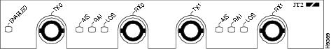
PA-2JT2 (see ) is a port adapter used on the VIP2 in the Cisco 7500 series routers, and in Cisco 7000 series routers using the RSP7000 and RSP7000CI. The JT2 port adapter is available as a spare part: Product Number PA-2JT2=.
Figure 1 PA-2JT2, Two-Port JT2 Port Adapter (Front Panel View)
Following are JT2 port adapter features and capabilities:
•
•
•
•
•
•
•
•
•
•
Port Adapter Locations on the VIP2
shows a VIP2 with two installed port adapters. shows a VIP2-50 with two installed port adapters. With the VIP2 oriented as shown, the left port adapter is in port adapter slot 0, and the right port adapter is in port adapter slot 1.
Port adapters have handles that allow for easy installation and removal; however, they are occasionally not shown in this publication to highlight port adapter faceplate detail.
In the Cisco 7000, Cisco 7507, and Cisco 7513 chassis the VIP2 is installed vertically. In the Cisco 7010 and Cisco 7505 chassis the VIP2 is installed horizontally. There are no interface processor or port adapter slot restrictions for the VIP2 and JT2 port adapter.
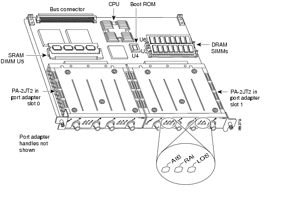
Figure 2 Two Port Adapters on the VIP2-40 (Horizontal Orientation Shown)
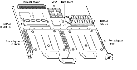
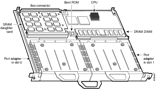
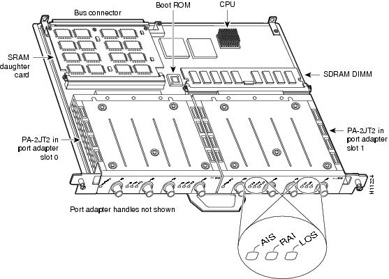
Figure 3 Two Port Adapters on a VIP2-50 (Horizontal Orientation Shown)
JT2 Port Adapter LEDs
The JT2 port adapter (see ) contains the enabled LED, which is standard on all port adapters; this green LED goes on after system initialization to indicate that the JT2 port adapter has been enabled for operation.
Figure 4 LEDs on the JT2 Port Adapter (Partial Front-Panel View)

The following conditions must be met before the enabled LED goes on:
•
•
•
If any of these conditions is not met, or if the initialization fails for other reasons, the enabled LED does not go on. The JT2 port adapter has three additional status LEDs for each JT2 port, which are labeled and function as follows:
•
•
•
JT2 Port Adapter Interface Connectors and Cables
The interface connectors on the JT2 port adapter are coaxial BNC types, with one connector/cable for transmit (TX) and one for receive (RX) for each interface port. Each BNC connection requires an external B-type or C-type DSU (with external grounding capability), with an optical fiber output, and that uses 75-ohm BNC terminations. (Cisco Systems does not supply 75-ohm coaxial cables; they are available from commercial cable vendors.)
Caution
Note
You must install a ferrite sleeve (also called a common-mode choke) on each 75-ohm coaxial cable to reduce the effects of electro-magnetic interference (EMI). (Cisco Systems supplies four ferrite sleeves with your JT2 port adapter; one ferrite sleeve for each of four 75-ohm coaxial cables you can attach to PA-2JT2.)
Note
Caution
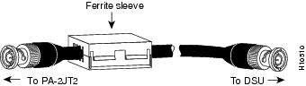
Figure 5 Attaching the Ferrite Sleeve around a Coaxial Cable
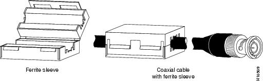
shows the typical 75-ohm coaxial cable you should use with PA-2JT2. Use only this type cable for all PA-2JT2 connections. Use one 75-ohm coaxial cable for each PA-2JT2 connection: RX0, TX0, RX1, and TX1.
Figure 6 75-Ohm Coaxial Cable with Ferrite Sleeve Attached
The pinout and signal descriptions for the BNC connectors on the JT2 port adapter are as follows:
•
•
JT2 Frame Format Description
Japan T2 (JT2) is a 6.312 kilobits-per-second (kbps) line format specified in ITU Recommendation G.704, and described in the Japanese NTT document Technical Reference for High-Speed Digital Leased Circuit Services.
A frame consists of 789 bits, and the frame repetition rate is 8 KHz, for a frame duration of 125 microseconds. There are four frames in a multiframe. In each frame, there are 98, 8-bit time slots (bit 1 through bit 784), starting with bit 1 in time slot 1 (TS1).
Note
The last five bits of the frame, bit 785 through bit 789, are called the F-bits. The F-bits contain the frame and multiframe alignment signal, which consists of nine bits (110010100) carried in the first two frames of the multiframe.
VIP2 and the JT2 Port Adapter
This section describes the JT2 port adapter and its use with the VIP2.
The following sections provide additional information specific to the JT2 port adapter and its use on the VIP2 in Cisco 7000 series and Cisco 7500 series routers:
•
•
•
shows a VIP2-40 with two JT2 port adapters in port adapter slots 0 and 1. Port adapters can be installed in either (or both) port adapter slot 0 or port adapter slot 1. You can install VIP2s in any interface processor slots in your Cisco 7500 series or Cisco 7000 series router.
Figure 7 VIP2-40 with Two JT2 Port Adapters (Horizontal Orientation Shown)
Note
shows a VIP2-50 with two JT2 port adapters installed in port adapter slots 0 and 1.
Figure 8 VIP2-50 with Two JT2 Port Adapters (Horizontal Orientation Shown)
Note
Caution To prevent system problems, do not remove port adapters from the VIP2 motherboard or attempt to install other port adapters on the VIP2 motherboard while the system is operating. To install or replace port adapters, first remove the VIP2 from its interface processor slot.
When only one port adapter is installed on a VIP2, a blank port adapter must fill the empty slot to allow the VIP2 and router chassis to conform to electromagnetic interference (EMI) emissions requirements, and so that air flows through the chassis properly. If you plan to install a new port adapter, you must first remove the blank port adapter.
Note
Step 1
Step 2
Caution
Step 3
Attaching JT2 Port Adapter Interface Cables
The 75-ohm coaxial cable (see ) required for the connections to PA-2JT2 are not available from Cisco Systems; they are available from commercial cable vendors. Use only 75-ohm coaxial cables for all PA-2JT2 connections. (For specific cable requirements, refer to the section "JT2 Port Adapter Interface Connectors and Cables" on page 10.)
Note
Figure 9 75-Ohm Coaxial Cable with Ferrite Sleeve Attached
Each E1-G.703/G.704 interface requires separate receive and transmit connections to an external B-type or C-type DSU. A DSU is available from outside vendors.
Use the following procedure to connect the 75-ohm coaxial cables to the JT2 port adapter:
Step 1
Figure 10 Connecting 75-Ohm Coaxial BNC Cables (Horizontal Orientation Shown)
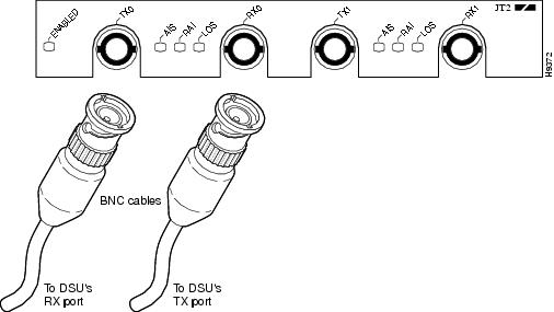
Note
Step 2
–
–
Caution
Step 3
Caution
Figure 11 Connecting 75-Ohm Coaxial BNC Cables to a DSU and Setting the DSU's External Ground
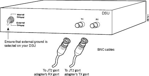
Step 4
This completes the procedure for attaching cables to the JT2 port adapter and an external B-type or C-type DSU.
Configuring the JT2 Interfaces
If you installed a new JT2 port adapter or if you want to change the configuration of an existing interface, you must enter configuration mode using the configure command. If you replaced a JT2 port adapter that was previously configured, the system will recognize the new JT2 interfaces and bring them up in their existing configuration.
After you verify that the new JT2 port adapter is installed correctly (the enabled LED goes on), use the privileged-level configure command to configure the new interfaces. Be prepared with the information you will need, such as the following:
•
•
•
For a summary of the configuration options available and additional instructions for configuring the JT2 interfaces on the JT2 port adapter, refer to the appropriate configuration publications listed in the section "Related Documentation" on page 2.
The configure command requires privileged-level access to the EXEC command interpreter, which usually requires a password. Contact your system administrator if necessary to obtain EXEC-level access.
Interface Processor Slot, Port Adapter Slot, and JT2 Interface Port Numbering
This section describes how to identify interface processor slot, port adapter slot, and interface port numbers.
Note
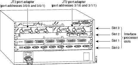
In the router, physical port addresses specify the actual physical location of each interface port on the router interface processor end. (See .) This address is composed of a three-part number in the format interface processor slot number/port adapter number/interface port number, as follows:
•
•
•
Interface ports on the JT2-equipped VIP2 maintain the same addresses regardless of whether other interface processors are installed or removed. However, when you move a VIP2 to a different slot, the first number in the address changes to reflect the new interface processor slot number.
shows the port adapter slots and interface ports of a sample Cisco 7505 system. The JT2 interface addresses on a JT2 port adapter in the first port adapter slot in interface processor slot 3, would be 3/0/0 and 3/0/1, from left to right. The JT2 interfaces on a JT2 port adapter in port adapter slot 1 would be numbered 3/1/0 and 3/1/1, from left to right.
Note
Figure 12 JT2 Interface Port Address Example (Cisco 7505 Shown)
You can identify interface ports by physically checking the slot/port-adapter/interface port location on the back of the router or by using show commands to display information about a specific interface or all interfaces in the router.
Configuring an Interface
This section describes a basic configuration. At any time you can exit the privileged level and return to the user level by entering disable at the prompt as follows:
Router# disableRouter>In the following basic configuration procedure, press the Return key after each step unless otherwise noted:
Step 1
Router# configure terminalEnter configuration commands, one per line. End with CNTL/Z.Router(config)#Step 2
Router(config)# interface serial 1/0/0Step 3
Router(config-int)# ip address 1.1.1.10 255.255.255.0Step 4
Step 5
Router(config-int)# no shutdownStep 6
Step 7
Step 8
Router# copy running-config startup-config[OK]Router#
To check the interface configuration using show commands, proceed to the section "Checking the Configuration."
Configuring CRC5
For data transmission at JT2 (6.312 Mbps), the G.704 standard suggests a 5-bit CRC. (Refer to ITU Recommendation G.704 for the definition of CRC5.)
To enable CRC5 on the JT2 interfaces, specify the slot and port address of the interface and the number of bits to use in the CRC (using crc 32), followed by the command crc bits 5. Press Ctrl-Z after altering the configuration and before exiting configuration mode.
The example that follows shows how to enable CRC5 generation on a JT2 interface and also how to set the CRC size to 32 bits; the example refers to JT2 interface 0 on the first JT2 port adapter on a VIP2 in interface processor slot 3:
Router# configure terminalEnter configuration commands, one per line. End with CNTL/Z.Router(config)# interface serial 3/0/0Router(config-int)# crc 32Router(config-int)# crc bits 5Router(config-int)# ^ZTo disable CRC5 and return to the default of no CRC error checking, specify the slot and port address and use the no crc bits 5 command.
Checking the Configuration
After configuring the new interface, use the show commands to display the status of the new interface or all interfaces, and use the ping command to check connectivity.
Using show Commands to Verify the New Interface Status
The following steps use show commands to verify that the new interfaces are configured and operating correctly.
Step 1
Step 2
Step 3
Step 4
Step 5
If the interface is down and you configured it as up, or if the displays indicate that the hardware is not functioning properly, ensure that the network interface is properly connected and terminated. If you still have problems bringing the interface up, contact a service representative for assistance.
Using show Commands to Display Interface and System Information
To display information about a specific interface, use the show interfaces command with the interface type and port address in the format show interfaces [type slot/port-adapter/port].
With the show interfaces [type slot/port-adapter/port] command, use arguments such as the interface type (serial) and the slot, port adapter, and port numbers (slot/port-adapter/port) to display information about a specific JT2 interface.
The following example shows all of the information specific to the first JT2 interface port (interface port 0) in interface processor slot 3, port adapter slot 0:
Router# sh int serial 3/0/0Serial3/0/0 is up, line protocol is upHardware is cyBus SerialInternet address is 1.0.0.1/8MTU 1500 bytes, BW 6312 Kbit, DLY 20000 usec, rely 255/255, load 26/255Encapsulation HDLC, loopback not set, keepalive not setLast input 00:04:31, output 00:04:31, output hang neverLast clearing of "show interface" counters 00:06:07Queueing strategy: fifoOutput queue 0/40, 0 drops; input queue 0/75, 0 drops5 minute input rate 162000 bits/sec, 8 packets/sec5 minute output rate 162000 bits/sec, 8 packets/sec20005 packets input, 20080520 bytes, 0 no bufferReceived 0 broadcasts, 0 runts, 0 giants0 input errors, 0 CRC, 0 frame, 0 overrun, 0 ignored, 0 abort20005 packets output, 20080520 bytes, 0 underruns0 output errors, 0 collisions, 0 interface resets0 output buffer failures, 0 output buffers swapped out0 carrier transitions0 cv errors, 0 crc5 errors, 0 frame errorsrxLOS inactive, rxLOF inactive, rxPAIS inactiverxAIS inactive, rxRAI inactive, rxHBER inactiveThe following counters appear in the output of the show interfaces serial command:
•
•
•
The following alarm indicators also appear in the output of the show interfaces serial command:
•
•
•
•
•
•
For complete command descriptions and examples, refer to the publications listed in the section "Related Documentation" on page 2.
The show version command displays the configuration of the system hardware (the number and type of each interface processor type installed), the software version, the names and sources of configuration files, and the boot images. Following is an example of the show version command:
Router# sh versionCisco Internetwork Operating System SoftwareIOS (tm) GS Software (RSP-JV-M), Version 11.1(12)CA1 [biff 137]Synced to mainline version: 11.1(8)Copyright (c) 1986-1997 by cisco Systems, Inc.Compiled Sat 10-May-97 19:19 by biffImage text-base: 0x600108A0, data-base: 0x609DA000ROM: System Bootstrap, Version 5.3(16645) [biff 571], INTERIM SOFTWAREROM: GS Software (RSP-BOOT-M), Experimental Version 11.1(618) [biff 114]Router uptime is 16 hours, 2 minutesSystem restarted by reloadSystem image file is "biff/rsp-jv-mz.g703", booted via tftp from 1.1.1.254cisco RSP2 (R4600) processor with 16384K bytes of memory.R4600 processor, Implementation 32, Revision 2.0Last reset from power-onG.703/E1 software, Version 1.0.G.703/JT2 software, Version 1.0.SuperLAT software copyright 1990 by Meridian Technology Corp).Bridging software.X.25 software, Version 2.0, NET2, BFE and GOSIP compliant.TN3270 Emulation software (copyright 1994 by TGV Inc).Chassis Interface.1 VIP2 controllers (2 Serial).2 Serial network interfaces.125K bytes of non-volatile configuration memory.16384K bytes of Flash PCMCIA card at slot 0 (Sector size 128K).8192K bytes of Flash internal SIMM (Sector size 256K).No slave installed in slot 7.Configuration register is 0x2The show controllers cbus command shows assorted information about the interfaces installed in the router. Following is an example of partial output from the show controllers cbus command, showing a JT2-equipped VIP2:
Router# sh cont cbusMEMD at 40000000, 2097152 bytes (unused 4352, recarves 18, lost 0)RawQ 48000100, ReturnQ 48000108, EventQ 48000110BufhdrQ 48000130 (2643 items), LovltrQ 48000148 (16 items, 2016 bytes)IpcbufQ 48000158 (24 items, 4096 bytes)IpcbufQ_classic 48000150 (8 items, 4096 bytes)3570 buffer headers (48002000 - 4800FF10)pool0: 10 buffers, 256 bytes, queue 48000138pool1: 720 buffers, 1536 bytes, queue 48000140pool2: 145 buffers, 4512 bytes, queue 48000160pool3: 4 buffers, 4544 bytes, queue 48000168slot9: VIP2, hw 2.3, sw 21.40, ccb 5800FFA0, cmdq 480000C0, vps 8192software loaded from flash slot0:vip2_21-40IOS (tm) VIP2 Software (SVIP-DW-M), Version 11.1(12)CA1 [biff 162]ROM Monitor version 17.0Mx JT2 Serial(2), HW Revision 0x2, FW Revision 1.26Serial5/0/0, applique is JT2 Unbalancedreceived clockrate 6155735gfreeq 48000140, lfreeq 48000278 (1536 bytes), throttled 0rxlo 4, rxhi 60, rxcurr 0, maxrxcurr 1txq 48001A80, txacc 48001A82 (value 39), txlimit 39To determine which type of port adapter is installed on a VIP2 in your system, use the show diag slot command. Specific port adapter information is displayed, as shown in the following example of an JT2 port adapter in a VIP2 in interface processor slot 9:
Router# sh diag 9Slot 9:Physical slot 9, ~physical slot 0x6, logical slot 9, CBus 0Microcode Status 0x4Master Enable, LED, WCS LoadedBoard is analyzedPending I/O Status: NoneEEPROM format version 1VIP2 controller, HW rev 2.3, board revision A0Serial number: 03515977 Part number: 73-1684-03Test history: 0x00 RMA number: 00-00-00Flags: cisco 7000 board; 7500 compatibleEEPROM contents (hex):0x20: 01 15 02 03 00 35 A6 49 49 06 94 03 00 00 00 000x30: 50 00 00 00 00 00 00 00 00 00 00 00 00 00 00 00Slot database information:Flags: 0x4 Insertion time: 0x3C58 (16:06:46 ago)Controller Memory Size: 16 MBytes DRAM, 1024 KBytes SRAMPA Bay 0 Information:JT2 Serial PA, 2 portsEEPROM format version 1HW rev 1.FF, Board revision UNKNOWNSerial number: 4294967295 Part number: 255-65535-255The show startup-config command displays the information from the configuration file used at system startup. Following is an example of partial output from the show startup-config command from a system with a JT2 port adapter installed and configured:
Router# sh startup-conf(additional display text omitted)hostname Router!interface Serial9/0/0ip address 28.0.0.1 255.0.0.0ip route-cache distributedno keepalivecrc5clock source internalno cdp enable!Using Software Configuration Commands Specific to the JT2 Port Adapter
The JT2 port adapter is capable of clocking transmitted data using an internal clock source or a clock derived from the received data stream. The default is a line-derived clock source; however, each JT2 interface will use its internal clock if no external clock is detected.
The clock source internal command sets the clock source as indicated. The no clock source command restores the system default.
By default, the system uses no CRC5. The crc bits 5 interface command allows the frame alignment search criteria to use CRC5. The no crc bits 5 interface command allows CRC5 to be excluded from the frame alignment search criteria.
Using the ping Command to Verify Network Connection
The packet internet groper (ping) command allows you to verify that an interface port is functioning properly and to check the path between a specific port and connected devices at various locations on the network. This section provides brief descriptions of the ping command. After you verify that the system and JT2-equipped VIP2 have booted successfully and are operational, you can use this command to verify the status of interface ports. Refer to the publications listed in the section "Related Documentation" on page 2, for detailed command descriptions and examples.
The ping command sends an echo request out to a remote device at an IP address that you specify. After sending a series of signals, the command waits a specified time for the remote device to echo the signals. Each returned signal is displayed as an exclamation point (!) on the console terminal; each signal that is not returned before the specified time-out is displayed as a period (.). A series of exclamation points (!!!!!) indicates a good connection; a series of periods (.....) or the messages [timed out] or [failed] indicate that the connection failed.
Following is an example of a successful ping command to a remote server with the address 1.1.1.10:
Router# ping 1.1.1.10 <Return>Type escape sequence to abort.Sending 5, 100-byte ICMP Echoes to 1.1.1.10, timeout is 2 seconds:!!!!!Success rate is 100 percent (5/5), round-trip min/avg/max = 1/15/64 msRouter#If the connection fails, verify that you have the correct IP address for the server and that the server is active (powered on); then repeat the ping command.
For additional descriptions of interface subcommands and the configuration options available for JT2-related interfaces, refer to the publications listed in the section "Related Documentation" on page 2.
Obtaining Documentation
These sections explain how to obtain documentation from Cisco Systems.
World Wide Web
You can access the most current Cisco documentation on the World Wide Web at this URL:
Translated documentation is available at this URL:
http://www.cisco.com/public/countries_languages.shtml
Documentation CD-ROM
Cisco documentation and additional literature are available in a Cisco Documentation CD-ROM package, which is shipped with your product. The Documentation CD-ROM is updated monthly and may be more current than printed documentation. The CD-ROM package is available as a single unit or through an annual subscription.
Ordering Documentation
You can order Cisco documentation in these ways:
•
http://www.cisco.com/cgi-bin/order/order_root.pl
•
http://www.cisco.com/go/subscription
•
Documentation Feedback
You can submit comments electronically on Cisco.com. In the Cisco Documentation home page, click the Fax or Email option in the "Leave Feedback" section at the bottom of the page.
You can e-mail your comments to bug-doc@cisco.com.
You can submit your comments by mail by using the response card behind the front cover of your document or by writing to the following address:
Cisco Systems
Attn: Document Resource Connection
170 West Tasman Drive
San Jose, CA 95134-9883
We appreciate your comments.Obtaining Technical Assistance
Cisco provides Cisco.com as a starting point for all technical assistance. Customers and partners can obtain online documentation, troubleshooting tips, and sample configurations from online tools by using the Cisco Technical Assistance Center (TAC) Web Site. Cisco.com registered users have complete access to the technical support resources on the Cisco TAC Web Site.
Cisco.com
Cisco.com is the foundation of a suite of interactive, networked services that provides immediate, open access to Cisco information, networking solutions, services, programs, and resources at any time, from anywhere in the world.
Cisco.com is a highly integrated Internet application and a powerful, easy-to-use tool that provides a broad range of features and services to help you with these tasks:
•
•
•
•
•
If you want to obtain customized information and service, you can self-register on Cisco.com. To access Cisco.com, go to this URL:
Technical Assistance Center
The Cisco Technical Assistance Center (TAC) is available to all customers who need technical assistance with a Cisco product, technology, or solution. Two levels of support are available: the Cisco TAC Web Site and the Cisco TAC Escalation Center.
Cisco TAC inquiries are categorized according to the urgency of the issue:
•
•
•
•
The Cisco TAC resource that you choose is based on the priority of the problem and the conditions of service contracts, when applicable.
Cisco TAC Web Site
You can use the Cisco TAC Web Site to resolve P3 and P4 issues yourself, saving both cost and time. The site provides around-the-clock access to online tools, knowledge bases, and software. To access the Cisco TAC Web Site, go to this URL:
All customers, partners, and resellers who have a valid Cisco service contract have complete access to the technical support resources on the Cisco TAC Web Site. The Cisco TAC Web Site requires a Cisco.com login ID and password. If you have a valid service contract but do not have a login ID or password, go to this URL to register:
http://www.cisco.com/register/
If you are a Cisco.com registered user, and you cannot resolve your technical issues by using the Cisco TAC Web Site, you can open a case online by using the TAC Case Open tool at this URL:
http://www.cisco.com/tac/caseopen
If you have Internet access, we recommend that you open P3 and P4 cases through the Cisco TAC Web Site.
Cisco TAC Escalation Center
The Cisco TAC Escalation Center addresses priority level 1 or priority level 2 issues. These classifications are assigned when severe network degradation significantly impacts business operations. When you contact the TAC Escalation Center with a P1 or P2 problem, a Cisco TAC engineer automatically opens a case.
To obtain a directory of toll-free Cisco TAC telephone numbers for your country, go to this URL:
http://www.cisco.com/warp/public/687/Directory/DirTAC.shtml
Before calling, please check with your network operations center to determine the level of Cisco support services to which your company is entitled: for example, SMARTnet, SMARTnet Onsite, or Network Supported Accounts (NSA). When you call the center, please have available your service agreement number and your product serial number.
This document is to be used in conjunction with the documents listed in the "Related Documentation" section.

Copyright © 1997-2002, Cisco Systems, Inc.
All rights reserved.

 Feedback
Contact Cisco
- Open a Support Case

- (Requires a Cisco Service Contract)