- Title and copyright: PA-2CE1 Channelized E1 Port Adapter Installation and Configuration
- Preface: PA-2CE1 Channelized E1 Port Adapter Installation and Configuration
- Overview: PA-2CE1 Channelized E1 Port Adapter Installation and Configurtion
- Preparing to Install the PA-2CE1 Channelized E1 Port Adapter Installation and Configuration
- Removing and Installing the PA-2CE1 Port Adapter
- Configuring the PA-2CE1 Port Adapter
PA-2CE1 Channelized E1 Port Adapter Installation and Configuration
Bias-Free Language
The documentation set for this product strives to use bias-free language. For the purposes of this documentation set, bias-free is defined as language that does not imply discrimination based on age, disability, gender, racial identity, ethnic identity, sexual orientation, socioeconomic status, and intersectionality. Exceptions may be present in the documentation due to language that is hardcoded in the user interfaces of the product software, language used based on RFP documentation, or language that is used by a referenced third-party product. Learn more about how Cisco is using Inclusive Language.
- Updated:
- September 14, 2007
Chapter: Overview: PA-2CE1 Channelized E1 Port Adapter Installation and Configurtion
Overview
This chapter describes the PA-2CE1 port adapter and contains the following sections:
•![]() LEDs
LEDs
•![]() Cables, Connectors, and Pinouts
Cables, Connectors, and Pinouts
•![]() Port Adapter Slot Locations on the Supported Platforms
Port Adapter Slot Locations on the Supported Platforms
•![]() Identifying Interface Addresses
Identifying Interface Addresses
Port Adapter Overview
The PA-2CE1, shown in Figure 1-1 and Figure 1-2, provide up to two channelized E1 (unbalanced 75-ohm or balanced 120-ohm) or ISDN PRI interfaces for connecting Cisco 7000 series routers to channel service units (CSUs). Each 2CE1 interface can transmit and receive data bidirectionally at the E1 rate of 2.048 megabits-per-second (Mbps).
Each 2CE1 interface connects to external networks through a single port that has a 15-pin, D-shell receptacle. You must use G.703 serial interface cables to connect unbalanced 75-ohm or balanced 120-ohm 2CE1 interfaces to a CSU. 2CE1 interfaces are configurable for balanced and unbalanced connections by setting jumpers on the 2CE1 printed circuit board. See the "Setting the PA-2CE1 Jumpers" section for balanced and unbalanced 2CE1 jumper settings.

Note ![]() While the VIP2 supports online insertion and removal (OIR), individual port adapters do not. To replace port adapters, you must first remove the VIP2 from the chassis, then replace port adapters as required.
While the VIP2 supports online insertion and removal (OIR), individual port adapters do not. To replace port adapters, you must first remove the VIP2 from the chassis, then replace port adapters as required.
The Cisco 7200 series routers support the OIR of all port adapter types.
Figure 1-1 PA-2CE1—Faceplate View—PA-2CE1/PRI-75 Shown
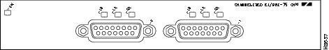
Figure 1-2 PA-2CE1—Faceplate View—PA-2CE1/PRI-120 Shown

When running channelized E1, each 2CE1 interface provides up to 31 E1 channel groups, which are numbered from 0 to 30. Each channel group provides up to 31, 64 kilobit-per-second (kbps) timeslots (DS0 channels), which are numbered 1 to 31. Multiple DS0 channels can be mapped to a single channel group. Each channel group is presented to the system as a serial interface that can be configured individually. Usable bandwidth for each channel group is calculated as n x 64 kbps, where n is a number of DS0 channels (1 to 31).
When running ISDN PRI, each 2CE1 interface provides 30 bearer (B) channels that can transmit and receive data at the rate of 64 kbps, full duplex, and one data (D) channel that can transmit and receive data at the rate of 16 kbps, full duplex. The B channels are used for transmitting user data. The D channel is used for call setup control and network connection teardown, and provides the communication from the router to the ISDN switch. The B and D channels are presented to the system as serial interfaces that support High-Level Data Link Control (HDLC) and Point-to-Point protocol (PPP) encapsulation. The PA-2CE1 support dial-on-demand routing (DDR) when running ISDN PRI.
LEDs
The PA-2CE1 has an enabled LED, standard on all port adapters, and six status LEDs, three for each port. (See Figure 1-3.)
Figure 1-3 LEDs on the PA-2CE1—Horizontal Orientation
After system initialization, the enabled LED goes on to indicate that the port adapter has been enabled for operation.
The following conditions must be met before the PA-2CE1 is enabled:
•![]() The PA-2CE1 is correctly connected and is receiving power.
The PA-2CE1 is correctly connected and is receiving power.
•![]() A valid system software image for the port adapter has been downloaded successfully.
A valid system software image for the port adapter has been downloaded successfully.
•![]() The system recognizes the PA-2CE1 or PA-2CE1-equipped VIP2.
The system recognizes the PA-2CE1 or PA-2CE1-equipped VIP2.
If any of the above conditions are not met, or if the initialization fails for other reasons, the enabled LED does not go on.
Table 1-1 lists LED colors and indications.
Cables, Connectors, and Pinouts
Three G.703 serial interface cables are available for use with the PA-2CE1; two cables for balanced 120-ohm 2CE1 interface connections, and one cable for an unbalanced 75-ohm 2CE1 interface connection.
Note ![]() The PA-2CE1 leave the factory configured for balanced 120-ohm or unbalanced 75-ohm connections. configuration of both PA-2CE1 interfaces. See the "Setting the PA-2CE1 Jumpers" section for instructions that explain how to change configuration of both PA-2CE1 interfaces.
The PA-2CE1 leave the factory configured for balanced 120-ohm or unbalanced 75-ohm connections. configuration of both PA-2CE1 interfaces. See the "Setting the PA-2CE1 Jumpers" section for instructions that explain how to change configuration of both PA-2CE1 interfaces.
All three cables have a 15-pin, D-shell (DB-15) connector at the router (VIP2 or Cisco 7200 series) end and either twin axial, RJ-45, or BNC connectors at the network end. Figure 1-4, Figure 1-5, and Figure 1-6 show the 2CE1 interface cables.
Following are the product numbers for the 2CE1 interface cables:
•![]() Twin axial cable—CAB-E1-TWINAX(=) or equivalent
Twin axial cable—CAB-E1-TWINAX(=) or equivalent
•![]() RJ-45 cable—CAB-E1-PRI(=) or equivalent
RJ-45 cable—CAB-E1-PRI(=) or equivalent
•![]() BNC cable—CAB-E1-BNC(=) or equivalent
BNC cable—CAB-E1-BNC(=) or equivalent
Figure 1-4 L2CE1 Twin Axial Cable for Balanced 120-Ohm Connections or ISDN PRI Connections
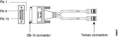
Figure 1-5 2CE1 RJ-45 Cable for Balanced 120-Ohm or ISDN PRI Connections
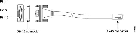
Figure 1-6 2CE1 BNC Cable for Unbalanced 75-Ohm Connections or ISDN PRI Connections
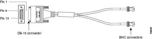
Table 1-2 lists connector pinouts for the 2CE1 interface cables.
|
|
|
|||||
|---|---|---|---|---|---|---|
|
|
|
|
|
|||
|
|
|
|
|
|
|
|
9 |
Tx Tip |
Tx-1 |
Tx Tip |
1 |
Tx Tip |
Tx Tip |
2 |
Tx Ring |
Tx-2 |
Tx Ring |
2 |
Tx Ring |
Tx Shield |
10 |
Tx Shield |
Shield |
Tx Shield |
3 |
Tx Shield |
- |
8 |
Rx Tip |
Rx-1 |
Rx Tip |
4 |
Rx Tip |
Rx Tip |
15 |
Rx Ring |
Rx-2 |
Rx Ring |
5 |
Rx Ring |
Rx Shield |
7 |
Rx Shield |
Shield |
Rx Shield |
6 |
Rx Shield |
- |
1 Any pins not described in this table are not connected. 2 Tx = transmit. Rx = receive. |
Port Adapter Slot Locations on the Supported Platforms
This section discusses port adapter slot locations on the supported platforms. The illustrations that follow summarize slot location conventions on each platform.
Cisco 7200 Series Routers Slot Numbering
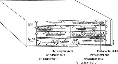
Figure 1-7 shows a Cisco 7206 with port adapters installed. In the Cisco 7206, port adapter slot 1 is in the lower left position, and port adapter slot 6 is in the upper right position. (The Cisco 7202, Cisco 7204, are not shown; however, the PA-2CE1 can be installed in any available port adapter slot.)
Figure 1-7 Port Adapter Slots in the Cisco 7206
VIP2 Slot Numbering
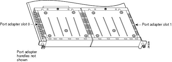
Figure 1-8 shows a partial view of a VIP motherboard with installed port adapters. With the motherboard oriented as shown in Figure 1-8, the left port adapter is in port adapter slot 0, and the right port adapter is in port adapter slot 1. The port adapter slots are always numbered 0 and 1.
Figure 1-8 VIP Motherboard with Two Port Adapters Installed—Horizontal Orientation
Note ![]() In the Cisco 7000, Cisco 7507, and Cisco 7513 chassis, the VIP motherboard is installed vertically. In the Cisco 7010 and Cisco 7505 chassis, the VIP motherboard is installed horizontally.
In the Cisco 7000, Cisco 7507, and Cisco 7513 chassis, the VIP motherboard is installed vertically. In the Cisco 7010 and Cisco 7505 chassis, the VIP motherboard is installed horizontally.
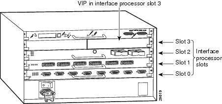
Interface processor slots are numbered as shown in Figure 1-9.
Figure 1-9 Interface Slot Numbers—Cisco 7505 Shown
Identifying Interface Addresses
This section describes how to identify interface addresses for the PA-2CE1 in supported platforms. Interface addresses specify the actual physical location of each interface on a router or switch.
Interfaces on the PA-2CE1 installed in a router maintain the same address regardless of whether other port adapters are installed or removed. However, when you move a port adapter to a different slot, the first number in the interface address changes to reflect the new port adapter slot number.
Interfaces on a PA-2CE1 installed in a VIP2 maintain the same address regardless of whether other interface processors are installed or removed. However, when you move a VIP2 to a different slot, the interface processor slot number changes to reflect the new interface processor slot.
Note ![]() Interface ports are numbered from left to right starting with 0.
Interface ports are numbered from left to right starting with 0.
Table 1-3 explains how to identify interface addresses.
|
|
|
|
|
|---|---|---|---|
Cisco 7200 series routers |
Port-adapter-slot-number/interface-port-number |
Port adapter slot—0 through 6 (depends on the number of slots in the router)1 Interface port—0 or 1 |
1/0 |
VIP2 in Cisco 7000 series or |
Interface-processor-slot-number/port-adapter-slot- |
Interface processor slot—0 through 12 (depends on the number of slots in the router) Port adapter slot—0 or 1 Interface port—0 or 1 |
3/1/0 |
1 Port adapter slot 0 is reserved for the Fast Ethernet port on the I/O controller (if present). |
Cisco 7200 Series Routers Interface Addresses
This section describes how to identify the interface addresses used for the PA-2CE1 in Cisco 7200 series routers. The interface address is composed of a two-part number in the format port-adapter-slot-number/interface-port-number. See Table 1-3 for the interface address format.
In Cisco 7200 series routers, port adapter slots are numbered from the lower left to the upper right, beginning with port adapter slot 1 and continuing through port adapter slot 2 for the Cisco 7202, slot 4 for the Cisco 7204, and slot 6 for the Cisco 7206. (Port adapter slot 0 is reserved for the optional Fast Ethernet port on the I/O controller—if present.)
The interface addresses of the interfaces on the PA-2CE1 in port adapter slot 1 are
1/0 through 1/7 (port adapter slot 1 and interfaces 0 through 7). If the PA-2CE1 was in port adapter slot 4, these same interfaces would be numbered 4/0 through 4/7 (port adapter slot 4 and interfaces
0 through 7).
The interface addresses of the interfaces on a PA-2CE1 in port adapter slot 2 are 2/0 and 2/1 (port adapter slot 2 and interfaces 0 and 1). If the PA-2CE1 was in port adapter slot 1, these same interfaces would be numbered 1/0 and 1/1 (port adapter slot 1 and interfaces 0 and 1).
VIP2 Interface Addresses
This section describes how to identify the interface addresses used for the PA-2CE1 on a VIP2 in Cisco 7000 series and Cisco 7500 series routers.
Note ![]() Although the processor slots in the 7-slot Cisco 7000 and Cisco 7507 and the 13-slot Cisco 7513 and Cisco 7576 are vertically oriented and those in the 5-slot Cisco 7010 and Cisco 7505 are horizontally oriented, all Cisco 7000 series and Cisco 7500 series routers use the same method for slot and port numbering.
Although the processor slots in the 7-slot Cisco 7000 and Cisco 7507 and the 13-slot Cisco 7513 and Cisco 7576 are vertically oriented and those in the 5-slot Cisco 7010 and Cisco 7505 are horizontally oriented, all Cisco 7000 series and Cisco 7500 series routers use the same method for slot and port numbering.
See Table 1-3 for the interface address format. The interface address is composed of a three-part number in the format interface-processor-slot-number/port-adapter-slot-number/interface-port-number.
If the VIP2 is inserted in interface processor slot 3, then the interface addresses of the PA-2CE1 are 3/1/0 through 3/1/7 (interface processor slot 3, port adapter slot 1, and interfaces 0 through 7). If the port adapter was in port adapter slot 0 on the VIP2, these same interface addresses would be numbered 3/0/0 through 3/0/7.
Note ![]() If you remove the VIP2 with the PA-2CE1 (shown in Figure 1-9) from interface processor
If you remove the VIP2 with the PA-2CE1 (shown in Figure 1-9) from interface processor
slot 3 and install it in interface processor slot 2, the interface addresses become 2/1/0 through 2/1/7.
 Feedback