- Title and copyright: PA-F/FD-SM and PA-F/FD-MM Full-Duplex FDDI Port Adapter Installation and Configuration
- Preface: PA-F/FD-SM and PA-F/FD-MM Full-Duplex FDDI Port Adapter Installation and Configuration
- Overview: PA-F/FD-SM and PA-F/FD-MM Full-Duplex FDDI Port Adapter Installation and Configuration
- Preparing to Install the PA-F/FD Port Adapter
- Attaching the PA-F/FD Port Adapter Cables
- Configuring the PA-F/FD Port Adapter
PA-F/FD-SM and PA-F/FD-MM Full-Duplex FDDI Port Adatpter Installation and Configuration
Bias-Free Language
The documentation set for this product strives to use bias-free language. For the purposes of this documentation set, bias-free is defined as language that does not imply discrimination based on age, disability, gender, racial identity, ethnic identity, sexual orientation, socioeconomic status, and intersectionality. Exceptions may be present in the documentation due to language that is hardcoded in the user interfaces of the product software, language used based on RFP documentation, or language that is used by a referenced third-party product. Learn more about how Cisco is using Inclusive Language.
- Updated:
- September 14, 2007
Chapter: Attaching the PA-F/FD Port Adapter Cables
Attaching the PA-F/FD Port Adapter Cables
To continue your PA-F/FD-SM and PA-F/FD-MM port adapter installation, you must attach the port adapter cables. The instructions that follow apply to all supported platforms. This chapter contains the following sections:
•![]() Attaching an Optical Bypass Switch
Attaching an Optical Bypass Switch
Connecting a FDDI Cable
Both single-mode and multimode dual-attachment connections are available. Fiber-optic cable connects directly to the FDDI ports. Single-mode transmission uses simplex or duplex SC-type transmit and receive cables. Multimode transmission uses media interface connector (MIC) cables.

Warning ![]() Invisible laser radiation may be emitted from the aperture ports of the single-mode FDDI products when no fiber cable is connected. Avoid exposure and do not stare into open apertures.
Invisible laser radiation may be emitted from the aperture ports of the single-mode FDDI products when no fiber cable is connected. Avoid exposure and do not stare into open apertures.
Connect cables for single-mode transmission on dual-attachment stations as shown in Figure 4-1.
Figure 4-1 Single-Mode Dual-Attachment Connection with Duplex and Simplex SC-Type Cables and Optical Bypass Control Cable
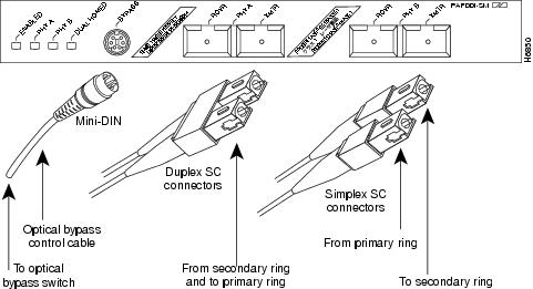

Note ![]() Use four single-mode SC-type simplex cables or two SC-type duplex cables for a dual-attachment connection.
Use four single-mode SC-type simplex cables or two SC-type duplex cables for a dual-attachment connection.
Connect cables for multimode transmission on dual-attachment stations as shown in Figure 4-2.
Figure 4-2 Multimode Dual-Attachment Connection with MIC Cables and Optical Bypass Control Cable

Attaching an Optical Bypass Switch
This section describes the procedures for attaching an optical bypass switch to the full-duplex FDDI port adapters. (Use these procedures for FDDI port adapters installed on a VIP, Catalyst RSM/VIP2, or in a Cisco 7200 series router [including a Cisco 7206 as a router shelf in a Cisco AS5800 Universal Access Server].)
An optical bypass switch is a device installed between the ring and the station that provides additional fault tolerance to the network. If a FDDI port adapter that is connected to a bypass switch fails or shuts down, the bypass switch activates automatically and allows the light signal to pass directly through it, bypassing the port adapter completely.
Following are general instructions for connecting an optical bypass switch to the FDDI port adapter; however, your particular bypass switch may require a different connection scheme. Use these steps and Figure 4-3 and as general guidelines, but for specific connection requirements, refer to the instructions provided by the manufacturer of the optical bypass switch.
1. ![]() Connect the bypass switch to the ring. Unless the documentation that accompanies the bypass switch instructs otherwise, observe the same guidelines for connecting the A/B ports on the bypass switch that you would to connect the ring directly to the FDDI ports. Use the receive label on the cable connectors as a key and connect the multimode or single-mode cables to the network (ring) side of the bypass switch as follows:
Connect the bypass switch to the ring. Unless the documentation that accompanies the bypass switch instructs otherwise, observe the same guidelines for connecting the A/B ports on the bypass switch that you would to connect the ring directly to the FDDI ports. Use the receive label on the cable connectors as a key and connect the multimode or single-mode cables to the network (ring) side of the bypass switch as follows:
a. ![]() Connect the cable coming in from the primary ring (from PHY B at the preceding station) to the PHY A receive port on the network (ring) side of the bypass switch. This also connects the signal going out to the secondary ring to the PHY A transmit port.
Connect the cable coming in from the primary ring (from PHY B at the preceding station) to the PHY A receive port on the network (ring) side of the bypass switch. This also connects the signal going out to the secondary ring to the PHY A transmit port.
b. ![]() Connect the cable coming in from the secondary ring (from PHY A at the preceding station) to the PHY B receive port on the network (ring) side of the bypass switch. This also connects the signal going out to the primary ring to the PHY B transmit port.
Connect the cable coming in from the secondary ring (from PHY A at the preceding station) to the PHY B receive port on the network (ring) side of the bypass switch. This also connects the signal going out to the primary ring to the PHY B transmit port.
2. ![]() Connect the bypass switch to the port adapter. Unless the documentation that accompanies the bypass switch instructs otherwise, consider the bypass an extension of the FDDI ports and connect A to A and B to B. The network cables are already connected to the bypass switch following the standard B-to-A/A-to-B scheme.
Connect the bypass switch to the port adapter. Unless the documentation that accompanies the bypass switch instructs otherwise, consider the bypass an extension of the FDDI ports and connect A to A and B to B. The network cables are already connected to the bypass switch following the standard B-to-A/A-to-B scheme.
a. ![]() Connect an interface cable between the PHY A port on the station (port adapter) side of the bypass switch and the FIP PHY A port.
Connect an interface cable between the PHY A port on the station (port adapter) side of the bypass switch and the FIP PHY A port.
b. ![]() Connect an interface cable between the PHY B port on the station (port adapter) side of the bypass switch and the FIP PHY B port.
Connect an interface cable between the PHY B port on the station (port adapter) side of the bypass switch and the FIP PHY B port.
3. ![]() Connect the bypass switch control cable. If the control cable on your optical bypass switch uses a mini-DIN connector, connect the cable directly to the female mini-DIN optical bypass port on the FDDI port adapter. If the switch uses a standard DIN connector, use the optical bypass adapter cable (Product Number CAB-FMDD=) supplied with each FDDI port adapter. Connect the DIN end of the adapter cable to the DIN on the control cable, and connect the mini-DIN end of the adapter cable to the mini-DIN optical bypass port on the FDDI port adapter.
Connect the bypass switch control cable. If the control cable on your optical bypass switch uses a mini-DIN connector, connect the cable directly to the female mini-DIN optical bypass port on the FDDI port adapter. If the switch uses a standard DIN connector, use the optical bypass adapter cable (Product Number CAB-FMDD=) supplied with each FDDI port adapter. Connect the DIN end of the adapter cable to the DIN on the control cable, and connect the mini-DIN end of the adapter cable to the mini-DIN optical bypass port on the FDDI port adapter.
A port for connecting an optical bypass switch is provided on the single-mode port adapter (PA-F/FD-SM, shown in ) and the multimode port adapter (PA-F/FD-MM, shown in ).
Figure 4-3 Optical Bypass Switch Connection—PA-F/FD-SM

Note ![]() Up to 160 milliamperes of current can be supplied to the optical bypass switch.
Up to 160 milliamperes of current can be supplied to the optical bypass switch.
Figure 4-4 Optical Bypass Switch Connection—PA-F/FD-MM

 Feedback