PA-A6 Port Adapter Installation and Configuration
Bias-Free Language
The documentation set for this product strives to use bias-free language. For the purposes of this documentation set, bias-free is defined as language that does not imply discrimination based on age, disability, gender, racial identity, ethnic identity, sexual orientation, socioeconomic status, and intersectionality. Exceptions may be present in the documentation due to language that is hardcoded in the user interfaces of the product software, language used based on RFP documentation, or language that is used by a referenced third-party product. Learn more about how Cisco is using Inclusive Language.
- Updated:
- September 14, 2007
Chapter: Overview: PA-A6
- Port Adapter Overview
- LEDs
- Cables and Connectors
- Additional Information
- SONET Distance Limitations
- SONET Frame Fundamentals
- Power Budget
- Approximating the PA-A6 Power Margin
- Multimode Power Budget Example with Sufficient Power for Transmission
- Multimode Power Budget Example of Dispersion Limit
- Single-Mode Transmission
- Using Statistics to Estimate the Power Budget
- References on Determining Attenuation and Power Budget
- Port Adapter Slot Locations on the Supported Platforms
- Cisco 7200 Series Routers and Cisco 7200 VXR Routers Slot Numbering
- Cisco 7201 Router Slot Numbering
- Cisco 7301 Router Slot Numbering
- Cisco 7304 PCI Port Adapter Carrier Card Slot Numbering
- Cisco 7401ASR Router Slot Numbering
- Cisco 7500 Series Routers with VIP Slot Numbering
- Cisco 7600 Series Routers with FlexWAN Slot Numbering
- Identifying Interface Addresses
- Cisco 7200 Series Routers and Cisco 7200 VXR Routers Interface Address
- Cisco 7201 Router Interface Address
- Cisco 7301 Router Interface Address
- Cisco 7304 PCI Port Adapter Carrier Card Interface Address
- Cisco 7401ASR Router Interface Address
- Cisco 7500 Series Routers VIP Interface Address
- Cisco 7600 Series Routers FlexWAN Module Interface Address
Overview
This chapter describes the PA-A6 port adapter and contains the following sections:
•![]() LEDs
LEDs
•![]() Port Adapter Slot Locations on the Supported Platforms
Port Adapter Slot Locations on the Supported Platforms
•![]() Identifying Interface Addresses
Identifying Interface Addresses
Port Adapter Overview
The PA-A6 is a series of single-width, single-port, ATM port adapters for the Cisco 7200 series routers, Cisco 7200 VXR routers, Cisco 7201 router, Cisco 7301 router, Cisco 7304 PCI Port Adapter Carrier Card in the Cisco 7304 router, Cisco 7401ASR router, Cisco 7500 series routers using VIP4-50 and VIP4-80, and Cisco 7600 series routers with FlexWAN module. With advanced ATM features, the PA-A6 supports broadband aggregation, WAN aggregation, and campus/MAN aggregation.
The PA-A6 includes three hardware versions that support the OC-3/STM-1 standards-based physical interfaces, as well as E3 and T3 interface modules:
•![]() OC-3/STM-1:
OC-3/STM-1:
–![]() Multimode—PA-A6-OC3MM (See Figure 1-1.)
Multimode—PA-A6-OC3MM (See Figure 1-1.)
–![]() Single-mode intermediate reach—PA-A6-OC3SMI (See Figure 1-2.)
Single-mode intermediate reach—PA-A6-OC3SMI (See Figure 1-2.)
–![]() Single-mode long reach—PA-A6-OC3SML (See Figure 1-3.)
Single-mode long reach—PA-A6-OC3SML (See Figure 1-3.)
•![]() E3—PA-A6-E3 (See Figure 1-4.)
E3—PA-A6-E3 (See Figure 1-4.)
•![]() T3—PA-A6-T3 (See Figure 1-5.)
T3—PA-A6-T3 (See Figure 1-5.)
Figure 1-1 PA-A6-OC3MM—Faceplate View
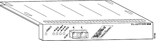
Figure 1-2 PA-A6-OC3SMI—Faceplate View

Figure 1-3 PA-A6-OC3SML—Faceplate View
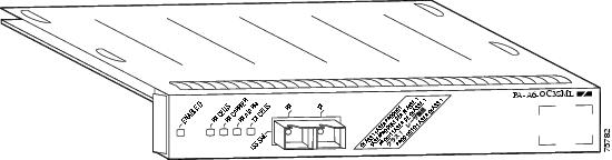
Figure 1-4 PA-A6-E3—Faceplate View
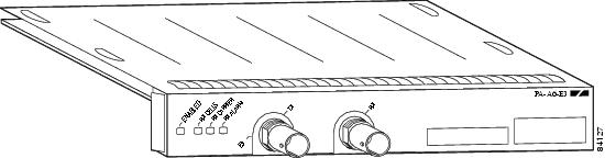
Figure 1-5 PA-A6-T3—Faceplate View

The PA-A6 can be installed on the Cisco 7200 series routers, Cisco 7200 VXR routers, Cisco 7201 router, Cisco 7301 router, Cisco 7304 PCI Port Adapter Carrier Card in the Cisco 7304 router, Cisco 7401ASR router, Cisco 7500 series routers using VIP4-50 and VIP4-80, and Cisco 7600 series routers using FlexWAN modules. There are no restrictions on slot locations or sequence; you can install a PA-A6 in any available port adapter slot.
Features
The PA-A6 supports the following features:
•![]() Up to 8191 simultaneously available virtual circuits (VCs)
Up to 8191 simultaneously available virtual circuits (VCs)
•![]() Up to 2000 simultaneous segmentations and reassemblies (SARs)
Up to 2000 simultaneous segmentations and reassemblies (SARs)
•![]() ATM adaptation layer 5 (AAL5) for data traffic
ATM adaptation layer 5 (AAL5) for data traffic
•![]() Full available bit rate (ABR) support (Traffic Management 4.0), all modes
Full available bit rate (ABR) support (Traffic Management 4.0), all modes
•![]() Traffic shaping per VC rates from 2.3 kbps to 155 Mbps, in 2.3-kbps increments
Traffic shaping per VC rates from 2.3 kbps to 155 Mbps, in 2.3-kbps increments
•![]() New ATMizer (ATMizerII+) running at 100 MHz
New ATMizer (ATMizerII+) running at 100 MHz
•![]() Increased SDRAM (32 MB) compared to PA-A3 (4 MB)
Increased SDRAM (32 MB) compared to PA-A3 (4 MB)
•![]() Increased SSRAM (1 MB per SAR) compared to PA-A3 (512 KB per SAR)
Increased SSRAM (1 MB per SAR) compared to PA-A3 (512 KB per SAR)
•![]() Line rate performance at 64-byte packets on unidirectional traffic with traffic shaping
Line rate performance at 64-byte packets on unidirectional traffic with traffic shaping
•![]() IP-to-ATM class of service (CoS)
IP-to-ATM class of service (CoS)
•![]() Non-real-time variable bit rate (nrt-VBR), unspecified bit rate (UBR), constant bit rate (CBR), and available bit rate (ABR) quality of service (QoS)
Non-real-time variable bit rate (nrt-VBR), unspecified bit rate (UBR), constant bit rate (CBR), and available bit rate (ABR) quality of service (QoS)
•![]() Operation, Administration, and Maintenance alarm indication signal (OAM AIS) cells
Operation, Administration, and Maintenance alarm indication signal (OAM AIS) cells
•![]() Online insertion and removal (OIR) on Cisco 7200 series routers, Cisco 7200VXR routers, Cisco 7201 router, Cisco 7301 router, and Cisco 7401ASR router
Online insertion and removal (OIR) on Cisco 7200 series routers, Cisco 7200VXR routers, Cisco 7201 router, Cisco 7301 router, and Cisco 7401ASR router
•![]() LAN Emulation (LANE)
LAN Emulation (LANE)
The PA-A6 supports the following protocols and services:
•![]() User-Network Interface (UNI) signaling
User-Network Interface (UNI) signaling
•![]() Integrated Local Management Interface (ILMI)
Integrated Local Management Interface (ILMI)
•![]() RFC 1483
RFC 1483
•![]() RFC 1577
RFC 1577
The PA-A6 complies with the environmental specifications listed in Table 1-1.
|
|
|
|---|---|
Operating temperature |
50 to 104oF (10 to 40oC) |
Humidity |
0 to 90%, noncondensing |
LEDs
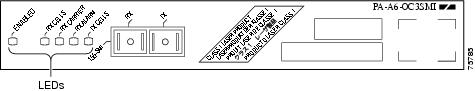
The PA-A6-OC3MM/SMI/SML port adapters have four status LEDs and one ENABLED LED. (See Figure 1-6.)
Figure 1-6 PA-A6 LEDs—Horizontal Orientation
The PA-A6-E3 and PA-A6-T3port adapters have three status LEDS (RF CELLS, RX CARRIER, RX ALARM). See Figure 1-4 and Figure 1-5.
After system initialization, the ENABLED LED goes on, indicating that the port adapter has been enabled for operation.
The following conditions must be met before the PA-A6 is enabled:
•![]() The port adapter is correctly connected and is receiving power.
The port adapter is correctly connected and is receiving power.
•![]() A valid system software image for the port adapter has been downloaded successfully.
A valid system software image for the port adapter has been downloaded successfully.
•![]() The system recognizes the port adapter.
The system recognizes the port adapter.
If any of these conditions are not met, or if the initialization fails for other reasons, the ENABLED LED does not go on.
Table 1-2 lists LED colors and function.
Cables and Connectors
The PA-A6 interfaces are full duplex. You must use the appropriate ATM interface cable to connect the PA-A6 with an external ATM network.
Table 1-3 summarizes the PA-A6 interface types, connectors, and cables.

Note ![]() The PA-A6 is considered an ATM end-point device.
The PA-A6 is considered an ATM end-point device.
OC-3c Multimode and Single-Mode Cables and Connectors
The OC-3c port on the PA-A6 is considered a DTE device.
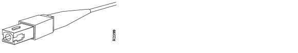
For SONET/SDH multimode and SONET/SDH single-mode connections, use one duplex SC connector (see Figure 1-7) or two simplex SC connectors (see Figure 1-8). These cables are not available from Cisco.
Note ![]() For information on SONET specifications for fiber-optic transmissions, understanding power budget, and assistance with approximating the power margin for multimode and single-mode transmissions, see the "Additional Information" section.
For information on SONET specifications for fiber-optic transmissions, understanding power budget, and assistance with approximating the power margin for multimode and single-mode transmissions, see the "Additional Information" section.
Figure 1-7 Duplex SC Connector

Figure 1-8 Simplex SC Connector
An appropriate fiber-optic cable must be used to connect the PA-A6 to the ATM switch or circuit. Single-mode and multimode cables should perform to the specifications listed in Table 1-4.
Note ![]() A single fiber link should not mix 62.5-micron and 50-micron cable.
A single fiber link should not mix 62.5-micron and 50-micron cable.
T3 and E3 Cables and Connectors
The PA-A6-T3 and PA-A6-E3 port adapters use a 75-ohm coaxial interface cable to connect your router to an ATM T3 or E3 network. The coaxial cables (Figure 1-9) conform to EIA/TIA-612 and EIA/TIA-613 specifications.
Figure 1-9 PA-A6-T3 and PA-A6-E3 Cables
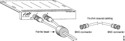
A single PA-A6-T3 or PA-A6-E3 contains one ATM T3 or E3 port that consists of two connectors: receive and transmit. The Cisco 75-ohm coaxial cable has two BNC connectors that attach to the T3 or E3 port receptacles.
The T3/E3 75-ohm coaxial cable, which comes with attached ferrite bead (see Figure 1-9), is available from Cisco in lengths of 10 feet (3.04 meters). The typical maximum distance between stations for T3 transmissions is 450 feet (137.2 meters) and for E3 transmissions is 1250 feet (381 meters).
Note ![]() To ensure compliance with electromagnetic interference (EMI) and European certification standards for emission control (EN55022/CISPR22 Class B for radiated emission levels), the TX and RX cables should be tied together along their entire length, and ferrite beads should be installed on each cable near the TX and RX connectors.
To ensure compliance with electromagnetic interference (EMI) and European certification standards for emission control (EN55022/CISPR22 Class B for radiated emission levels), the TX and RX cables should be tied together along their entire length, and ferrite beads should be installed on each cable near the TX and RX connectors.
The PA-A6-T3 and PA-A6-E3 provide an interface to ATM switching fabrics for the bidirectional transmission and reception of data at rates of up to 45 Mbps (for T3) and 34 Mbps (for E3).
Additional Information
This section describes the SONET specifications for fiber-optic transmissions, defines the power budget, and helps you approximate the power margin for multimode and single-mode transmissions. This section includes the following subsections:
•![]() Approximating the PA-A6 Power Margin
Approximating the PA-A6 Power Margin
•![]() Multimode Power Budget Example with Sufficient Power for Transmission
Multimode Power Budget Example with Sufficient Power for Transmission
•![]() Multimode Power Budget Example of Dispersion Limit
Multimode Power Budget Example of Dispersion Limit
•![]() Using Statistics to Estimate the Power Budget
Using Statistics to Estimate the Power Budget
•![]() References on Determining Attenuation and Power Budget
References on Determining Attenuation and Power Budget
SONET Distance Limitations
The SONET specification for fiber-optic transmission defines two types of fiber: single mode and multimode. Modes can be thought of as bundles of light rays entering the fiber at a particular angle. Single-mode fiber allows only one mode of light to propagate through the fiber, whereas multimode fiber allows multiple modes of light to propagate through the fiber. Because multiple modes of light propagating through the fiber travel different distances depending on the entry angles, causing them to arrive at the destination at different times (a phenomenon called modal dispersion), single-mode fiber is capable of higher bandwidth and greater cable run distances than multimode fiber.
The typical maximum distances for single-mode and multimode transmissions, as defined by SONET, are in Table 1-5. If the distance between two connected stations is greater than this maximum distance, significant signal loss can result, making transmission unreliable.
|
|
|
|---|---|
Single-mode long reach (SML) |
Up to 24.8 miles (40 kilometers) |
Single-mode intermediate reach (SMI) |
Up to 9.3 miles (15 kilometers) |
Multimode (MM) |
Up to 1.2 miles (2 kilometers) |
1 Table 1-5 gives typical results. Use the power budget calculations described in the following sections to determine the actual distances. |
SONET Frame Fundamentals
SONET is a Layer 1 protocol that uses a layered architecture. The following illustration shows SONET's three layers: section, line, and path. The Section OverHead (SOH) and Line OverHead (LOH) form the Transport OverHead (TOH), while the Path OverHead (POH) and actual payload form the Synchronous Payload Envelope (SPE). (See Figure 1-10.)
Figure 1-10 Three SONET Layers of a SONET Frame
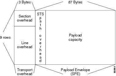
Each layer adds some number of overhead bytes to the SONET frame.
Table 1-6 illustrates the overhead bytes of the SONET frame.
Power Budget
To design an efficient optical data link, evaluate the power budget. The power budget is the amount of light available to overcome attenuation in the optical link and to exceed the minimum power that the receiver requires to operate within its specifications. Proper operation of an optical data link depends on modulated light reaching the receiver with enough power to be correctly demodulated.
Attenuation, caused by the passive media components (cables, cable splices, and connectors), is common to both multimode and single-mode transmission.
The following variables reduce the power of the signal (light) transmitted to the receiver in multimode transmission:
•![]() Chromatic dispersion (spreading of the signal in time because of the different speeds of light wavelengths)
Chromatic dispersion (spreading of the signal in time because of the different speeds of light wavelengths)
•![]() Modal dispersion (spreading of the signal in time because of the different propagation modes in the fiber)
Modal dispersion (spreading of the signal in time because of the different propagation modes in the fiber)
Attenuation is significantly lower for optical fiber than for other media. For multimode transmission, chromatic and modal dispersion reduce the available power of the system by the combined dispersion penalty. The power lost over the data link is the sum of the component, dispersion, and modal losses.
Table 1-7 lists the factors of attenuation and dispersion for typical fiber-optic cable.
|
|
|
|
|---|---|---|
Attenuation |
0.5 dB/km |
1.0 dB/km |
Dispersion |
No limit |
500 MHz/km1 |
1 The product of bandwidth and distance must be less than 500 MHz/km. |
Approximating the PA-A6 Power Margin
The LED used for a multimode transmission light source creates multiple propagation paths of light, each with a different path length and time requirement to cross the optical fiber, causing signal dispersion (smear). Higher-order mode loss (HOL) results from light from the LED entering the fiber and being radiated into the fiber cladding. A worst-case estimate of power margin (PM) for multimode transmissions assumes minimum transmitter power (PT), maximum link loss (LL), and minimum receiver sensitivity (PR). The worst-case analysis provides a margin of error; not all of the parts of an actual system will operate at the worst-case levels.
The power budget (PB) is the maximum possible amount of power transmitted. The following equation lists the calculation of the power budget:
PB = PT - PR
PB = -20 dBm - (-30 dBm)
PB = 10 dBm
The power margin calculation is derived from the power budget minus the link loss, as follows:
PM = PB - LL
If the power margin is positive, as a rule, the link will work.
Table 1-8 lists the factors that contribute to link loss and the estimate of the link loss value attributable to those factors.
After you calculate the power budget minus the data link loss, the result should be greater than zero. Circuits with results that are less than zero may have insufficient power to operate the receiver.
The SONET specification requires that the signal must meet the worst-case parameters listed in Table 1-9.
|
|
|
|
|
|---|---|---|---|
PT |
-5 dBm |
-15 dBm |
-20 dBm |
PR |
-34 dBm |
-31 dBm |
-30 dBm |
PB |
29 dBm |
16 dBm |
10 dB |
Multimode Power Budget Example with Sufficient Power for Transmission
The following is a sample multimode power budget calculated based on the following variables:
Length of multimode link = 3 kilometers (km)
Four connectors
Three splices
Higher-order mode loss (HOL)
Clock recovery module (CRM)
Estimate the power budget as follows:
PB = 10 dB - 3 km (1.0 dB/km) - 4 (0.5 dB) - 3 (0.5 dB) - 0.5 dB (HOL) - 1 dB (CRM)
PB = 10 dB - 3 dB - 2 dB - 1.5 dB - 0.5 dB - 1 dB
PB = 2 dB
The positive value of 2 dB indicates that this link would have sufficient power for transmission.
Multimode Power Budget Example of Dispersion Limit
Following is an example with the same parameters as the previous example, but with a multimode link distance of 4 km:
PB = 10 dB - 4 km (1.0 dB/km) - 4 (0.5 dB) - 3 (0.5 dB) - 0.5 dB (HOL) - 1 dB (CRM)
PB = 10 dB - 4 dB - 2 dB - 1.5 dB - 0.5 dB - 1 dB
PB = 1 dB
The value of 1 dB indicates that this link would have sufficient power for transmission. But due to the dispersion limit on the link (4 km x 155.52 MHz > 500 MHz/km), this link would not work with multimode fiber. In this case, single-mode fiber would be the better choice.
Single-Mode Transmission
The single-mode signal source is an injection laser diode. Single-mode transmission is useful for longer distances, because there is a single transmission path within the fiber and smear does not occur. In addition, chromatic dispersion is also reduced because laser light is essentially monochromatic.
The receiver for single-mode intermediate reach (SMI) cannot be overloaded by the SMI transmitter and does not require a minimum fiber cable length or loss. The maximum receive power for single-mode long reach (SML) is -10 dBm, and the maximum transmit power is 0 dBm. The SML receiver can, therefore, be overloaded when short lengths of fiber are used. Overloading the receiver will not damage the receiver but can cause unreliable operation. To prevent overloading an SML receiver connected with short fiber links, insert a minimum 10-dB attenuator on the link between any single-mode long-reach transmitter and the receiver.
Using Statistics to Estimate the Power Budget
Statistical models more accurately determine the power budget than the worst-case method. Determining the link loss with statistical methods requires accurate knowledge of variations in the data link components. Statistical power budget analysis is beyond the scope of this document. For further information, refer to UNI Forum specifications, ITU-T standards, and your equipment specifications.
References on Determining Attenuation and Power Budget
The following publications contain information on determining attenuation and power budget:
•![]() T1E1.2/92-020R2 ANSI, the Draft American National Standard for Telecommunications entitled Broadband ISDN Customer Installation Interfaces: Physical Layer Specification
T1E1.2/92-020R2 ANSI, the Draft American National Standard for Telecommunications entitled Broadband ISDN Customer Installation Interfaces: Physical Layer Specification
•![]() Power Margin Analysis, AT&T Technical Note, TN89-004LWP, May 1989
Power Margin Analysis, AT&T Technical Note, TN89-004LWP, May 1989
Port Adapter Slot Locations on the Supported Platforms
This section discusses port adapter slot locations on the supported platforms. The illustrations that follow summarize slot location conventions on each platform:
•![]() Cisco 7200 Series Routers and Cisco 7200 VXR Routers Slot Numbering
Cisco 7200 Series Routers and Cisco 7200 VXR Routers Slot Numbering
•![]() Cisco 7201 Router Slot Numbering
Cisco 7201 Router Slot Numbering
•![]() Cisco 7301 Router Slot Numbering
Cisco 7301 Router Slot Numbering
•![]() Cisco 7304 PCI Port Adapter Carrier Card Slot Numbering
Cisco 7304 PCI Port Adapter Carrier Card Slot Numbering
•![]() Cisco 7401ASR Router Slot Numbering
Cisco 7401ASR Router Slot Numbering
•![]() Cisco 7500 Series Routers with VIP Slot Numbering
Cisco 7500 Series Routers with VIP Slot Numbering
•![]() Cisco 7600 Series Routers with FlexWAN Slot Numbering
Cisco 7600 Series Routers with FlexWAN Slot Numbering
Cisco 7200 Series Routers and Cisco 7200 VXR Routers Slot Numbering
Cisco 7202 routers have two port adapter slots. The slots are numbered from left to right, slot 1 and slot 2. You can place the port adapters in either of the slots (slot 1 or slot 2). The Cisco 7202 router is not shown.
Cisco 7204 routers and Cisco 7204VXR routers have four slots for port adapters, and one slot for an input/output (I/O) controller. The slots are numbered from the lower left to the upper right, beginning with slot 1 and continuing through slot 4. You can place the port adapters in any of the slots (slot 1 through slot 4). Slot 0 is always reserved for the I/O controller. Figure 1-11 shows the slot numbering on a Cisco 7204VXR router. The Cisco 7204 router is not shown.
Figure 1-11 Port Adapter Slots in the Cisco 7204VXR Router
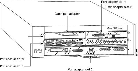
Cisco 7206 routers and Cisco 7206VXR routers have six slots for port adapters, and one slot for an input/output (I/O) controller. The slots are numbered from the lower left to the upper right, beginning with slot 1 and continuing through slot 6. You can place the port adapters in any of the six slots (slot 1 through slot 6). Slot 0 is always reserved for the I/O controller. Figure 1-12 shows the slot numbering on a Cisco 7206VXR router.The Cisco 7206 router is not shown.
Figure 1-12 Port Adapter Slots in the Cisco 7206VXR Router
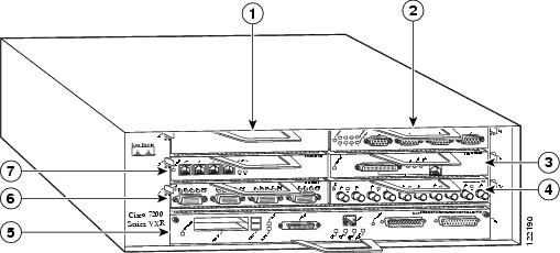
|
|
Port adapter slot 5 (blank) |
|
Port adapter slot 0 (Fast Ethernet port) |
|
|
Port adapter slot 6 |
|
Port adapter slot 1 |
|
|
Port adapter slot 4 |
|
Port adapter slot 3 |
|
|
Port adapter slot 2 |
Cisco 7201 Router Slot Numbering
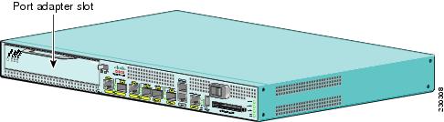
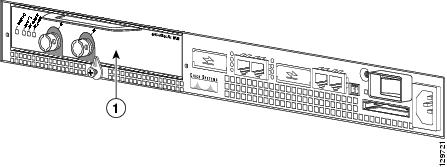
Figure 1-13 shows the front view of a Cisco 7201 router with a port adapter installed. There is only one port adapter slot (slot 1) in a Cisco 7201 router.
Figure 1-13 Port Adapter Slot in the Cisco 7201 Router
Cisco 7301 Router Slot Numbering
Figure 1-14 shows the front view of a Cisco 7301 router with a port adapter installed. There is only one port adapter slot (slot 1) in a Cisco 7301 router.
Figure 1-14 Port Adapter Slot In the Cisco 7301 Router
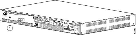
|
|
Port adapter slot 1 |
Cisco 7304 PCI Port Adapter Carrier Card Slot Numbering
Figure 1-15 shows the module slot numbering on a Cisco 7304 router. The Cisco 7304 PCI port adapter carrier card installs into Cisco 7304 router module slots 2 through 5. The port adapter slot number is the same as the module slot number. Slot 0 and slot 1 are reserved for the NPE module or NSE module.
Figure 1-15 Module Slots on the Cisco 7304 Router
|
|
PCI carrier card—slot 4 |
|
PCI carrier card—slot 2 |
|
|
PCI carrier card—slot 5 |
|
PCI carrier card—slot 3 |
|
|
NPE or NSE module—slot 0 |
|
NPE or NSE module—slot 1 |
Cisco 7401ASR Router Slot Numbering
Figure 1-16 shows the front view of a Cisco 7401ASR router with a port adapter installed. There is only one port adapter slot (slot 1) in a Cisco 7401ASR router.
Figure 1-16 Port Adapter Slot in the Cisco 7401ASR Router
|
|
Port adapter slot 1 |
Cisco 7500 Series Routers with VIP Slot Numbering
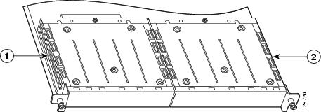
The PA-A6 is supported on the VIP4-50 and VIP4-80 versatile interface processors used in Cisco 7500 series routers. In the Cisco 7505 router, the VIP motherboard is installed horizontally in the VIP slot. In the Cisco 7507 router and Cisco 7513 router, the VIP motherboard is installed vertically in the VIP slot. The port adapter can be installed in either bay (port adapter slot 0 or 1) on the VIP. The bays are numbered from left to right on the VIP. Figure 1-17 shows the slot numbering on a VIP.
Figure 1-17 VIP Slot Locations
|
|
VIP port adapter slot 0 |
|
VIP port adapter slot 1 |
Cisco 7505 routers have four slots for port adapters, and one slot for a Route Switch Processor (RSP). The slots are numbered from bottom to top. You can place the port adapters in any of the VIP interface slots (slot 0 through 3). One slot is always reserved for the RSP. Figure 1-18 shows the slot numbering on a Cisco 7505 router.
Figure 1-18 VIP Slots in the Cisco 7505 Router
|
|
RSP |
|
VIP interface—slot 1 |
|
|
VIP interface—slot 3 |
|
VIP interface—slot 0 |
|
|
VIP interface—slot 2 |
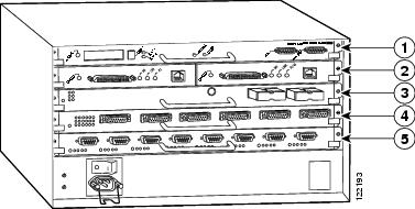
Cisco 7507 routers have five slots for port adapters, and two slots for RSPs. The slots are numbered from left to right. You can place the port adapters in any of the VIP interface slots (slot 0, 1, 4, 5, or 6). Slots 2 and 3 are always reserved for RSPs. Figure 1-19 shows the slot numbering on a Cisco 7507 router.
Figure 1-19 VIP Slots in the Cisco 7507 Router
|
|
VIP interface—slot 0 |
|
VIP interface—slot 4 |
|
|
VIP interface—slot 1 |
|
VIP interface—slot 5 |
|
|
RSP—slot 2 |
|
VIP interface—slot 6 |
|
|
RSP—slot 3 |
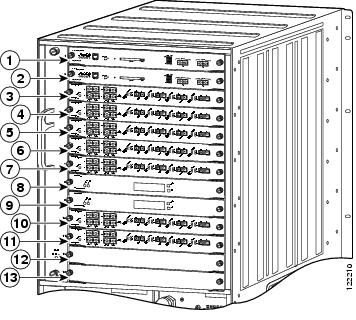
Cisco 7513 routers have eleven slots for port adapters, and two slots for RSPs. The slots are numbered from left to right. You can place the port adapters in any of the VIP interface slots (slots 0 through 5, or slots 9 through 12). Slots 6 and 7 are always reserved for RSPs. Figure 1-20 shows the slot numbering on a Cisco 7513 router.
Figure 1-20 VIP Slots in the Cisco 7513 Router
Cisco 7600 Series Routers with FlexWAN Slot Numbering
The PA-A6 is supported on a FlexWAN or Enhanced FlexWAN module used in the Cisco 7603 router, Cisco 7606 router, Cisco 7609 router, and Cisco 7613 router. The FlexWAN module can be installed in any slot of a Cisco 7600 series router except slot 1, which is reserved for the supervisor engine. Port adapters can be installed into either port adapter bay 0 or port adapter bay 1 on the FlexWAN module.
Cisco 7603 routers have two slots for port adapters. The slots are numbered from top to bottom. You can place the port adapters in either of the FlexWAN module slots (slot 2 or 3). Slot 1 is always reserved for the supervisor engine. Figure 1-21 shows the slot numbering on a Cisco 7603 router.
Figure 1-21 FlexWAN and Enhanced FlexWAN Slots in the Cisco 7603 Router
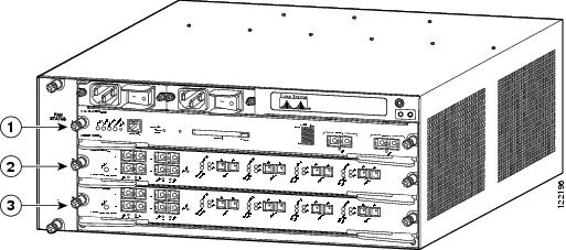
|
|
Supervisor engine—slot 1 |
|
FlexWAN module—slot 3 |
|
|
FlexWAN module—slot 2 |
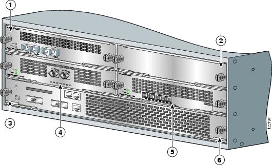
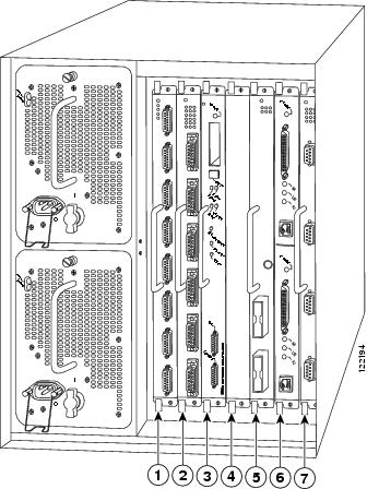
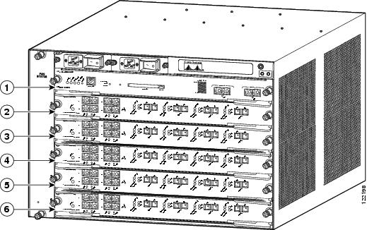
Cisco 7606 routers have five slots for port adapters. The slots are numbered from top to bottom. You can place the port adapters in any of the FlexWAN module slots (slots 2 through 6). Slot 1 is always reserved for the supervisor engine. Figure 1-22 shows the slot numbering on a Cisco 7606 router.
Figure 1-22 FlexWAN and Enhanced FlexWAN Slots in the Cisco 7606 Router
|
|
Supervisor engine—slot 1 |
|
FlexWAN module—slot 4 |
|
|
FlexWAN module—slot 2 |
|
FlexWAN module—slot 5, |
|
|
FlexWAN module—slot 3 |
|
FlexWAN module—slot 6 |
Note ![]() Some of the slots used for the FlexWAN module on the Cisco 7606 router can also be used for other supervisor engines, RSPs, or OSMs. For details, refer to the Cisco 7600 Series Router Installation Guide at the following URL: http://www.cisco.com/en/US/products/hw/routers/ps368/products_installation_guide_book09186a008080269a.html
Some of the slots used for the FlexWAN module on the Cisco 7606 router can also be used for other supervisor engines, RSPs, or OSMs. For details, refer to the Cisco 7600 Series Router Installation Guide at the following URL: http://www.cisco.com/en/US/products/hw/routers/ps368/products_installation_guide_book09186a008080269a.html
Cisco 7609 routers have eight slots for port adapters. The slots are numbered from right to left. You can place the port adapters in any of the FlexWAN module slots (slots 2 through 9). Slot 1 is always reserved for the supervisor engine. Figure 1-23 shows the slot numbering on a Cisco 7609 router.
Figure 1-23 FlexWAN and Enhanced FlexWAN Slots in the Cisco 7609 Router
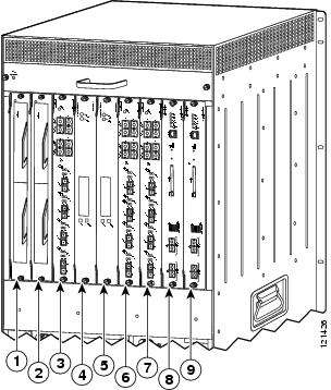
Note ![]() Some of the slots used for the FlexWAN module on the Cisco 7609 router can also be used for other supervisor engines, RSPs, or OSMs. For details, refer to the Cisco 7600 Series Router Installation Guide at the following URL: http://www.cisco.com/en/US/products/hw/routers/ps368/products_installation_guide_book09186a008080269a.html
Some of the slots used for the FlexWAN module on the Cisco 7609 router can also be used for other supervisor engines, RSPs, or OSMs. For details, refer to the Cisco 7600 Series Router Installation Guide at the following URL: http://www.cisco.com/en/US/products/hw/routers/ps368/products_installation_guide_book09186a008080269a.html
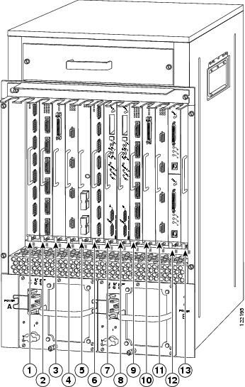
Cisco 7613 routers have twelve slots for port adapters. The slots are numbered from top to bottom. You can place the port adapters in any of the FlexWAN module slots (slots 2 through 13). Slot 1 is always reserved for the supervisor engine. Figure 1-24 shows the slot numbering on a Cisco 7613 router.
Figure 1-24 FlexWAN and Enhanced FlexWAN Slots in the Cisco 7613 Router
Note ![]() Some of the slots used for the FlexWAN module on the Cisco 7613 router can also be used for other supervisor engines, RSPs, or OSMs. For details, refer to the Cisco 7600 Series Router Installation Guide at the following URL: http://www.cisco.com/en/US/products/hw/routers/ps368/products_installation_guide_book09186a008080269a.html
Some of the slots used for the FlexWAN module on the Cisco 7613 router can also be used for other supervisor engines, RSPs, or OSMs. For details, refer to the Cisco 7600 Series Router Installation Guide at the following URL: http://www.cisco.com/en/US/products/hw/routers/ps368/products_installation_guide_book09186a008080269a.html
Identifying Interface Addresses
This section describes how to identify the interface addresses for the PA-A6 in supported platforms. Interface addresses specify the actual physical location of each interface on a router or switch.
Interfaces on a PA-A6 installed in a router maintain the same address regardless of whether other port adapters are installed or removed. However, when you move a port adapter to a different slot, the first number in the interface address changes to reflect the new port adapter slot number.
Interfaces on a PA-A6 installed in a VIP or FlexWAN module maintain the same address regardless of whether other interface processors or modules are installed or removed. However, when you move a VIP or FlexWAN module to a different slot, the interface processor or module slot number changes to reflect the new interface processor or module slot.
Note ![]() Interface ports are numbered from left to right starting with 0.
Interface ports are numbered from left to right starting with 0.
The following subsections describe the interface address formats for the supported platforms:
•![]() Cisco 7200 Series Routers and Cisco 7200 VXR Routers Interface Address
Cisco 7200 Series Routers and Cisco 7200 VXR Routers Interface Address
•![]() Cisco 7201 Router Interface Address
Cisco 7201 Router Interface Address
•![]() Cisco 7301 Router Interface Address
Cisco 7301 Router Interface Address
•![]() Cisco 7304 PCI Port Adapter Carrier Card Interface Address
Cisco 7304 PCI Port Adapter Carrier Card Interface Address
•![]() Cisco 7401ASR Router Interface Address
Cisco 7401ASR Router Interface Address
•![]() Cisco 7500 Series Routers VIP Interface Address
Cisco 7500 Series Routers VIP Interface Address
•![]() Cisco 7600 Series Routers FlexWAN Module Interface Address
Cisco 7600 Series Routers FlexWAN Module Interface Address
Table 1-10 summarizes the interface address formats for the supported platforms.
|
|
|
|
|
|---|---|---|---|
Cisco 7200 series routers and Cisco 7200 VXR routers (7202, 7204, 7204VXR, 7206, 7206VXR) |
Port-adapter-slot-number/interface-port-number |
Port adapter slot—11 through 6 (depends on the number of slots in the router) Interface port—0 |
1/0 |
Cisco 7201 router |
Port-adapter-slot-number/interface-port number |
Port adapter slot—always 1 Interface port—0 |
1/0 |
Cisco 7301 router |
Port-adapter-slot-number/interface-port number |
Port adapter slot—always 1 Interface port—0 |
1/0 |
Cisco 7304 PCI port adapter carrier card in Cisco 7304 router |
Module-slot-number/interface-port-number |
Module slot— 2 through 5 Interface port—0 |
3/0 |
Cisco 7401ASR router |
Port-adapter-slot-number/interface-port number |
Port adapter slot—always 1 Interface port—0 |
1/0 |
Cisco 7500 series routers (7505, 7507, 7513) with VIP4-50, VIP4-80 |
Interface-processor-slot-number/port-adapter -slot-number/interface-port number |
Interface processor slot—0 through 12 (depends on the number of slots in the router) Port adapter slot— 0 or 1 Interface port—0 |
3/1/0 |
Cisco 7600 series routers (7603, 7606, 7609, 7613) with FlexWAN or Enhanced FlexWAN |
Module-slot-number/port-adapter-bay-number/ |
Module slot —22 through 13 (depends on the number of slots in the router) Port adapter bay— 0 or 1 Interface port—0 |
3/0/0 |
1 Port adapter slot 0 is reserved for the Fast Ethernet port on the I/O controller (if present). 2 Slot 1 is reserved for the supervisor engine. If a redundant supervisor engine is used, it must go in slot 2; otherwise, slot 2 can be used for other modules. |
Cisco 7200 Series Routers and Cisco 7200 VXR Routers Interface Address
In Cisco 7200 series routers and Cisco 7200 VXR routers, port adapter slots are numbered from the lower left to the upper right, beginning with slot 1 and continuing through slot 2 for the Cisco 7202, slot 4 for the Cisco 7204 and Cisco 7204VXR, and slot 6 for the Cisco 7206 and Cisco 7206VXR. Port adapters can be installed in any available port adapter slot from 1 through 6 (depending on the number of slots in the router). (Slot 0 is reserved for the I/O controller.) See Figure 1-12.
The interface address is composed of a two-part number in the format port-adapter-slot-number/interface-port-number. See Table 1-10. For example, if a single-port PA-A6 is installed in slot 1of a Cisco 7200 series router, the interface address would be 1/0. If a single-port PA-A6 were installed in slot 4, the interface address would be 4/0.
Cisco 7201 Router Interface Address
In the Cisco 7201 router, only one slot accepts port adapters and it is numbered slot 1. See Figure 1-13.
The interface address is composed of a two-part number in the format port-adapter-slot-number/interface-port-number. See Table 1-10. For example, if a single-port PA-A6 is installed on a Cisco 7201 router, the interface address would be 1/0.
Cisco 7301 Router Interface Address
In the Cisco 7301 router, only one slot accepts port adapters and it is numbered slot 1. See Figure 1-14.
The interface address is composed of a two-part number in the format port-adapter-slot-number/interface-port-number. See Table 1-10. For example, if a single-port PA-A6 is installed on a Cisco 7301 router, the interface address would be 1/0.
Cisco 7304 PCI Port Adapter Carrier Card Interface Address
In the Cisco 7304 router, port adapters are installed in a Cisco 7304 PCI port adapter carrier card, which installs in Cisco 7304 router module slots 2 through 5. The port adapter slot number is the same as the module slot number. See Figure 1-15.
The interface address is composed of a two-part number in the format module-slot-number/interface-port-number. See Table 1-10. For example, if a single-port PA-A6 is installed in the Cisco 7304 PCI port adapter carrier card in Cisco 7304 router module slot 3, the interface address would be 3/0.
Cisco 7401ASR Router Interface Address
In the Cisco 7401ASR router, only one slot accepts port adapters and it is numbered slot 1. See Figure 1-16.
The interface address is composed of a two-part number in the format port-adapter-slot-number/interface-port-number. See Table 1-10. For example, if a single-port PA-A6 is installed on a Cisco 7401ASR router, the interface address would be 1/0.
Cisco 7500 Series Routers VIP Interface Address
In Cisco 7500 series routers, port adapters are installed on a versatile interface processor (VIP), which installs in interface processor slots 0 through 12 (depending on the number of slots in the router). The port adapter can be installed in either bay (port adapter slot 0 or 1) on the VIP. See Figure 1-17, Figure 1-18, Figure 1-19, and Figure 1-20.
The interface address for the VIP is composed of a three-part number in the format interface-processor-slot-number/port-adapter-slot-number/interface-port-number. See Table 1-10.
The first number identifies the slot in which the VIP is installed (slot 0 through 12, depending on the number of slots in the router).
The second number identifies the bay (port adapter slot) on the VIP in which the port adapter is installed (0 or 1). The bays are numbered from left to right on the VIP.
The third number identifies the physical port number (interface port number) on the port adapter. The port numbers always begin at 0 and are numbered from left to right. The number of additional ports depends on the number of ports on the port adapter. The PA-A6 is a single-port port adapter, therefore the port is always 0.
For example, if a single-port PA-A6 is installed in a VIP in interface processor slot 3, port adapter slot 1, the interface addresses would be 3/1/0.
Note ![]() Although the processor slots in the seven-slot Cisco 7507 and the thirteen-slot Cisco 7513 chassis are vertically oriented and those in the five-slot Cisco 7505 are horizontally oriented, all Cisco 7500 series routers use the same method for slot and port numbering.
Although the processor slots in the seven-slot Cisco 7507 and the thirteen-slot Cisco 7513 chassis are vertically oriented and those in the five-slot Cisco 7505 are horizontally oriented, all Cisco 7500 series routers use the same method for slot and port numbering.
Cisco 7600 Series Routers FlexWAN Module Interface Address
In Cisco 7600 series routers, port adapters are installed in a FlexWAN or Enhanced FlexWAN module, which installs in module slots 2 through 13 (depending on the number of slots in the router). The port adapter can be installed in either bay (port adapter bay 0 or 1) on the FlexWAN or Enhanced FlexWAN module. See Figure 1-21, Figure 1-22, Figure 1-23, and Figure 1-24.
The interface address is composed of a three-part number in the format module-slot-number/port-adapter-bay-number/interface-port-number. See Table 1-10.
The first number identifies the module slot of the chassis in which the FlexWAN module is installed (slot 2 through slot 3, 6, 9, or 13 depending on the number of slots in the chassis). These module slots are generally numbered from top to bottom, starting with 1. The Cisco 7609 is the exception with slots numbered right to left, starting with 1.
The second number identifies the bay of the FlexWAN module in which the port adapter is installed (0 or 1). The bays are numbered from left to right on the FlexWAN module.
The third number identifies the physical port number on the port adapter. The PA-A6 is a single-port port adapter, therefore the port is always 0
For example, if a single-port PA-A6 is installed in the FlexWAN module, which is inserted in module slot 3, port adapter bay 0, then the interface address of the port adapter would be 3/0/0 (module slot 3, port adapter bay 0, and port 0). If the same port adapter is in port adapter bay 1 on the FlexWAN module, the interface addresses would be numbered 3/1/0.
 Feedback