Cisco HX220c M4 HyperFlex Node Installation Guide
Bias-Free Language
The documentation set for this product strives to use bias-free language. For the purposes of this documentation set, bias-free is defined as language that does not imply discrimination based on age, disability, gender, racial identity, ethnic identity, sexual orientation, socioeconomic status, and intersectionality. Exceptions may be present in the documentation due to language that is hardcoded in the user interfaces of the product software, language used based on RFP documentation, or language that is used by a referenced third-party product. Learn more about how Cisco is using Inclusive Language.
- Updated:
- March 22, 2016
Chapter: RAID Controller Considerations
HBA Card Considerations
Supported HBAs and Required Cables
This node supports the HBA options and cable requirements shown in Table C-1 .
|
|
|
Maximum Drives Controlled |
|
|
|
|---|---|---|---|---|---|
|
|
HBA Card Firmware Compatibility
Firmware on the HBA must be verified for compatibility with the current Cisco IMC and BIOS versions that are installed on the node. If not compatible, upgrade or downgrade the HBA firmware accordingly.
Use the procedures in the GUI or CLI Cisco UCS Manager Firmware Management Guide for your release.
HBA Cabling
This section includes the following topics:
Cable Routing
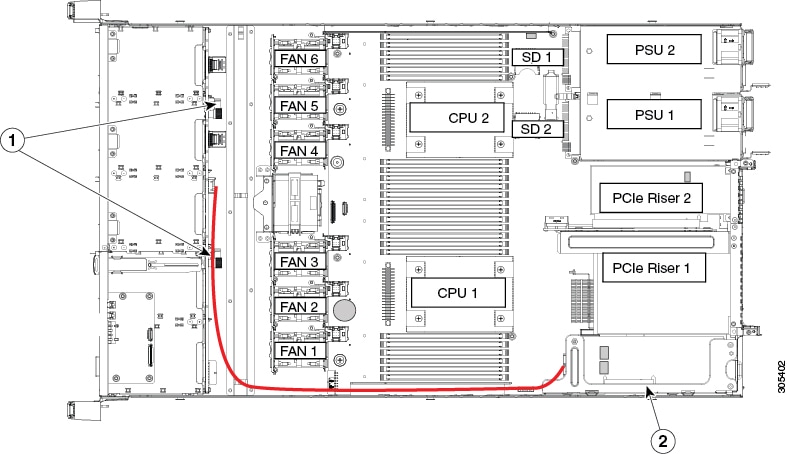
The RAID controller connectors in this node are shown in Figure C-1.
The red line shows the recommended cable routing path from the Cisco modular HBA card to the drive backplane. Cable guides on the chassis wall help route the cables.
Figure C-1 RAID Controller Connectors
|
|
|
Cisco HX220c M4 Node Cabling
Cisco UCS 12G Modular HBA cabling
This non-RAID option can control up to eight SAS/SATA drives.
The required UCS-220CBLMR8= cable kit has one Y-cable with a mini-SAS HD double connector on one end and two mini-SAS HD single connectors on the other end.
Step 1![]() Connect the mini-SAS double connector to the modular HBA card.
Connect the mini-SAS double connector to the modular HBA card.
Step 2![]() Connect single connector PORT A to the PORT A connector on the backplane.
Connect single connector PORT A to the PORT A connector on the backplane.
Step 3![]() Connect single connector PORT B to the PORT B connector on the backplane.
Connect single connector PORT B to the PORT B connector on the backplane.
 Feedback