Cisco Nexus 9000 Series NX-OS VXLAN Configuration Guide, Release 10.4(x)
Bias-Free Language
The documentation set for this product strives to use bias-free language. For the purposes of this documentation set, bias-free is defined as language that does not imply discrimination based on age, disability, gender, racial identity, ethnic identity, sexual orientation, socioeconomic status, and intersectionality. Exceptions may be present in the documentation due to language that is hardcoded in the user interfaces of the product software, language used based on RFP documentation, or language that is used by a referenced third-party product. Learn more about how Cisco is using Inclusive Language.
Micro-segmentation for VXLAN Fabrics Using Group Policy Option (GPO)
Overview
Network administrators can use micro-segmentation to logically group network resources based on specific criteria such as
application attributes. You can use micro-segmentation with Security Groups (SGs) and Security Group ACLs (SGACLs) to create
and enforce tailored application centric security policies between security groups regardless of network topology.
In traditional data center environments, the application or workload security is often implemented at the perimeter or the
north-south boundary where users from outside the data center fabric enter. This is often implemented using perimeter firewalls
and other security inspection devices. However, this approach is not effective against the advanced nature of the latest attacks.
The attack surface spans the entire data center including the east-west and north-south flows.
Using micro-segmentation with security groups and security group ACLs, this feature can provide an effective security solution
to the users of NX-OS platforms. Micro-segmentation provides more flexibility and lower complexity than traditional general
purpose Access Control Lists (ACLs). With micro-segmentation, organizations can provide specific policies that dictate how
the application workloads communicate regardless of where these applications reside within the network.
GPO
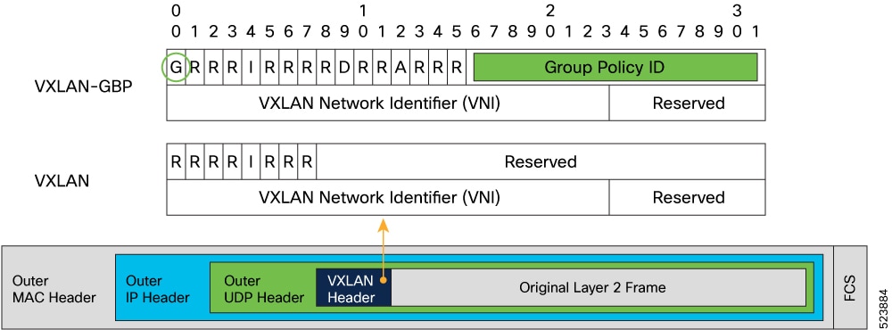
Group Policy Option (GPO) is a backward-compatible extension to VXLAN that adds a Security Group Tag (SGT) to the VXLAN header
for security policy enforcement purposes.
Figure 1. Security Group Tags on VXLAN Header
In a GPO enabled VXLAN network, you can create Security Groups in the VXLAN EVPN fabrics to define segmentation. By defining
smaller, isolated application segments, you can deploy micro-segmentation policies that allow for better control over the
flow of network traffic among the application tiers and across applications. Micro-segmentation ensures that security policies
are applied only where they are needed, improving application and workload security, thereby improving the security posture.
You can classify network resources to a Security Group tag based on multiple attributes. Traffic between Security Groups can
be controlled by Security Group Access Control Lists (SGACLs) also known as Security Contracts, which match source and destination
Security Groups using Security Group tags.
Terminology
Security Group (SG)
A Security Group is a logical entity that contains a collection of physical or virtual network endpoints that are classified
based on attributes or selectors.
Source Security Group Tags (S-SGT)
Tags derived from source attributes are called Source Security Group Tags.
Destination Security Group Tags (D-SGT)
Tags derived from destination attributes are called Destination Security Group Tags.
Security Group Access Control List (SGACL)
An SGACL uses Security Tags for enforcing specific security rules (L4 filters) between different Security Groups. The Tags
are derived from IP, VLAN, and VM Attributes. SGACL allows to enforce security policies between SGs. An SGACL is also known
as a Contract. In some parts of the document, SGACL is referred to as contract.
VRF Level Enforcement
The security group selectors define which endpoints and external IPs belong to the Security Group. Security Groups can contain
endpoints, which are part of different VRFs. If endpoints part of different VRFs are associated to the same SG, communication
between them would be possible only after applying the required VRF route-leaking configuration.
By default, a newly defined Tenant VRF has policy enforcement set to Unenforced. This means that even if classification criteria
and SGACLs between secure groups were to be provisioned, no policy enforcement would be possible. To enable SGACL enforcement
in the VRF, the VRF needs to be explicitly configured in Enforced mode.
When you configure the VRF in enforced mode, you can define the default behavior to be either of the following:
Deny: All unicast traffic flows are dropped unless permitted by an Allowlist.
Permit: All unicast traffic flows are allowed unless denied by a Denylist.
Hosts within a SG can communicate freely without explicit SGACLs. SGACLs create security rules, only.
Guidelines and Limitations
GPO has the following guidelines and limitations:
Beginning with Cisco NX-OS Release 10.4(3)F, GPO is supported on the following platforms:
9300-FX3
9300-GX
9300-GX2
SGACLs are supported only in the context of a VXLAN EVPN deployment. SGACL cannot be deployed on non-VXLAN enabled VRFs.
SGACLs are not applicable to BUM and multicast traffic. System generated default permit policies exist for BUM and multicast
traffic.
You cannot configure VLAN-based Security Group selectors with a VLAN part of system reserved-vlan-range values.
If VLAN-based Security Group selectors are already configured, system-reserved-vlan-range cannot be modified to include VLAN
values used in the SG selectors.
Configuring Micro-Segmentation using GPO
Enabling GPO
Perform the following steps to enable the micro-segmentation feature. The first time you enable the feature, the routing template
should be configured to system routing template-security-groups.
Warning
This routing template is required for feature security-group. Ensure the feature is enabled after applying the template mode.
This routing template requires extended SSD re-partitioning. This can be achieved by executing the copy running-config startup-config and system flash sda resize extended commands.
Subsequent disabling and re-enabling of the feature security-group can be done without requiring a switchreload.
SUMMARY STEPS
configure terminal
system routing template-security-groups
copy running-config startup-config
system flash sda resize extended
[no] feature security-group
show nve peers detail
DETAILED STEPS
Command or Action
Purpose
Step 1
configure terminal
Example:
switch# configure terminal
Enters global configuration mode.
Step 2
system routing template-security-groups
Example:
switch(config-if)# system routing template-security-groups
Changes the switch routing profile.
Note
The routing template should be configured to system routing template-security-groups. Routing template requires extended SSD partitioning executed through system flash sda resize which will initiate a reload.
Copies the running configuration to the startup configuration.
Step 4
system flash sda resize extended
Example:
switch(config-if)# system flash sda resize extended
!!!! WARNING !!!!

      Attempts will be made to preserve drive contents during
      the resize operation, but risk of data loss does exist.
      Backing up of bootflash, logflash, and running configuration
      is recommended prior to proceeding.

!!!! WARNING !!!!


current scheme is
sda           8:0    0 119.2G  0 disk
|-sda1        8:1    0   512M  0 part
|-sda2        8:2    0    32M  0 part /mnt/plog
|-sda3        8:3    0   128M  0 part /mnt/pss
|-sda4        8:4    0 110.5G  0 part /bootflash
|-sda5        8:5    0    64M  0 part /mnt/cfg/0
|-sda6        8:6    0    64M  0 part /mnt/cfg/1
`-sda7        8:7    0     8G  0 part /logflash


 target scheme is
sda           8:0    0 120GB|250GB  0 disk
|-sda1        8:1    0   512M       0 part
|-sda2        8:2    0    32M       0 part /mnt/plog
|-sda3        8:3    0   128M       0 part /mnt/pss
|-sda4        8:4    0    rem       0 part /bootflash
|-sda5        8:5    0   1.0G       0 part /mnt/cfg/0
|-sda6        8:6    0   1.0G       0 part /mnt/cfg/1
|_sda7        8:7    0    39G       0 part /logflash

Continue? (y/n)  [n] y
  A module reload is required for the resize operation to proceed
  Please, do not power off the module during this process.
Increases storage space.
Step 5
[no] feature security-group
Example:
switch(config-if)# feature security-group
Enables the group policy option (GPO) feature. Use the 'no' prefix to disable the feature. The GPO feature can be disabled
or enabled in runtime.
Step 6
show nve peers detail
Example:
switch(config-if)# show nve peers detail
Details of nve Peers:
----------------------------------------
Peer-Ip: 1.1.1.1
    NVE Interface       : nve1
    Peer State          : Up
    Peer Uptime         : 1d12h
    Router-Mac          : 5292.ca60.1b08
    Peer First VNI      : 101
    Time since Create   : 1d12h
    Configured VNIs     : 100-101,200-201
    Provision State     : peer-add-complete
    Learnt CP VNIs      : 100-101,200-201
    vni assignment mode : SYMMETRIC
    Peer Location       : FABRIC
    Group policy option : yes
----------------------------------------
Verifies that the group policy option is enabled for peer device.
Creating a Security Group
Perform the following steps to create or update a Security Group and to configure member selection criteria. To select group
members, you can specify any combination of the following attributes:
IPv4 address or subnet for connected-endpoints and external-subnets.
IPv6 address or subnet for connected-endpoints and external-subnets.
Match VLAN at the switch level.
SUMMARY STEPS
configure terminal
security-groupsg-idnamesg-name
[no] match [connected-endpoints | external-subnets] vrfvrf-name[ipv4|ipv6]ip-prefix
[no] match vlanvlan-id
show security-group idsg-id
DETAILED STEPS
Command or Action
Purpose
Step 1
configure terminal
Example:
switch# configure terminal
switch(config)#
Enters global configuration mode.
Step 2
security-groupsg-idnamesg-name
Example:
switch(config)# security-group 100 name webservers
switch(config-security-group)#
Creates (or selects an existing) security group whose unique ID is sg-id and whose name is sg-name.
Step 3
[no] match [connected-endpoints | external-subnets] vrfvrf-name[ipv4|ipv6]ip-prefix
Example:
switch(config-security-group)# match connected-endpoints vrf vrf_blue ipv4 61.1.1.141/32
switch(config-security-group)# match external-subnets vrf vrf_blue ipv4 10.0.0.0/8
switch(config-security-group)# match connected-endpoints vrf vrf_blue ipv6 61:1:1:2:1::141/128
switch(config-security-group)# match external-subnets vrf vrf_blue ipv6 10:11:12:13::/64
This command is an IPv4-VRF or IPv6-VRF selector for a host (connected-endpoints) or external (external-subnets) resource.
Use the 'no' prefix to disable the specific classification.
Step 4
[no] match vlanvlan-id
Example:
switch(config-security-group)# match vlan 10
Configures VLAN selector at the switch level.
Step 5
show security-group idsg-id
Example:
switch(config-if)# show security-group id 100
Security Group ID 100 , Name webservers
  Selector Type : External IPv4 Selector
    VRF-Name                IPv4-Address/mask-len
    blue                    10.1.1.3/32
    blue                    10.1.1.4/32
  Selector Type : Host IPv4 Selector
    VRF-Name                IPv4-Address/mask-len
    blue                    10.1.1.3/32
    blue                    10.1.1.4/32
Verifies the group policy selectors.
Creating a Security Class-Map
A Class-Map classifies network traffic based on various match criteria configured within a class map. Perform the following
steps to create a Security Class-Map to define the filters identifying specific traffic flows.
SUMMARY STEPS
configure terminal
class-map type security match-anyweb-class
match [default | ip | ipv4 | ipv6]
DETAILED STEPS
Command or Action
Purpose
Step 1
configure terminal
Example:
switch# configure terminal
switch(config)#
Enters global configuration mode.
Step 2
class-map type security match-anyweb-class
Example:
switch(config)# class-map type security match-any web-class2
Create a security class-map to identify specific traffic flows.
Step 3
match [default | ip | ipv4 | ipv6]
Example:
switch(config-cmap-sec)# match ipv4 udp sport 399 to 402 dport 400 to 403
switch(config-cmap-sec)# match ipv6 udp sport 399 to 402 dport 400 to 403
Configures the security class by matching based on traffic type.
Creating a Security Policy-Map
A policy map defines a policy stating what happens to traffic that is classified using class maps and ACLs. Perform the following
steps to create a Security Policy-Map to define the action (permit, deny, log traffic flows identified by the previously created
security class-map.
SUMMARY STEPS
configure terminal
policy-map type securitypolicy-map
class web-class
[no] [permit | deny | log]
DETAILED STEPS
Command or Action
Purpose
Step 1
configure terminal
Example:
switch# configure terminal
switch(config)#
Enters global configuration mode.
Step 2
policy-map type securitypolicy-map
Creates a security policy-map.
Step 3
class web-class
Specifies a security class-map to be associated with the policy-map to define the traffic the rule will be applied to.
Step 4
[no] [permit | deny | log]
Defines action to be taken on matching traffic.
Deny: Deny the matching traffic.
Log: Log the matching traffic.
Permit: Permit the matching traffic.
Permit is the default action if none specified. Log action can be set with permit or deny. Matching traffic is logged under show logging ip access-list cache [detail].
Configuring Security contracts between Security Groups
This procedure creates an SGACL (contract) to enforce a security policy between Security Groups.
Applies the previously defined security policy map, with the corresponding action, between the specified security groups.
The default option is bidir if no direction is specified. Default option bidir applies the SGACL to traffic in both direction (in example, 100 to 200 and 200 to 100).
For example, if you create a security rule between SG 100 and SG 200 with a filter that specifies destination port 80, the
use of bidir ensures that a rule is also applied for communication between SG 200 and SG 100 with source port 80 so that the two-ways
communication can be successfully established.
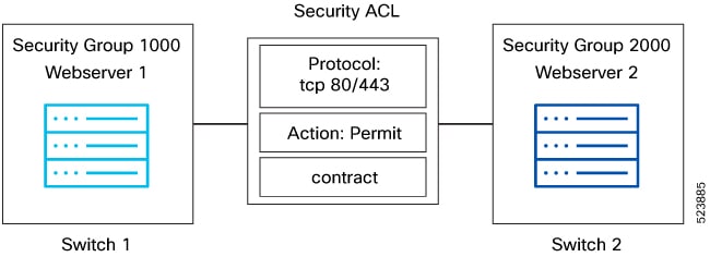
Configuration Examples for GPO
Figure 2. Creating Security Group
Step 1: Enabling GPO.
Switch1# configure terminal
Switch1(config)# system routing template-security-groups
Switch1(config)#feature security-group

Switch2# configure terminal
Switch2(config)# system routing template-security-groups
Switch2(config)#feature security-group
Step 2: Creating a security class-map to identify specific traffic flows.
Switch1(config)#class-map type security match-any web-class
match ipv4 tcp dport 443
match ipv4 tcp dport 80

Switch2(config)#class-map type security match-any web-class
match ipv4 tcp dport 443
match ipv4 tcp dport 80
Step 3: Creating a security policy map
Switch1(config)#policy-map type security policyMap1
class web-class
[no] [permit | deny | log]
Switch2(config)#policy-map type security policyMap1
class web-class
[no] [permit | deny | log]
Step 4: Creating security group.
switch1(config)security-group 1000 name webserver1
switch1(config-security-group)# match connected-endpoints vrf vrf_blue ipv4 61.1.1.141/32
switch1(config-security-group)# match external-subnets vrf vrf_blue ipv4 10.0.0.0/8
switch1(config-security-group)# match connected-endpoints vrf vrf_blue ipv6 61:1:1:2:1::141/128
switch1(config-security-group)# match external-subnets vrf vrf_blue ipv6 10:11:12:13::/64
switch1(config-security-group)# match connected-endpoints vrf vrf_red ipv4 100.5.150.125/32
switch1(config-security-group)# match connected-endpoints vrf vrf_red ipv6 100:1:1:495::125/128
switch1(config-security-group)# match external-subnets vrf vrf_red ipv4 11.0.0.0/8
switch1(config-security-group)# match vlan 10

switch2(config)security-group 2000 name webserver2
switch2(config-security-group)# match connected-endpoints vrf vrf_blue ipv4 61.1.1.142/32
switch2(config-security-group)# match external-subnets vrf vrf_blue ipv4 20.0.0.0/8
switch2(config-security-group)# match connected-endpoints vrf vrf_blue ipv6 61:1:1:2:1::142/128
switch2(config-security-group)# match external-subnets vrf vrf_blue ipv6 20:11:12:14::/64
switch2(config-security-group)# match connected-endpoints vrf vrf_red ipv4 100.5.150.126/32
switch2(config-security-group)# match connected-endpoints vrf vrf_red ipv6 100:1:1:495::126/128
switch2(config-security-group)# match external-subnets vrf vrf_red ipv4 21.0.0.0/8
switch2(config-security-group)# match vlan 10
Displays all the security-group related configurations in the switch.
switch1(config)# show run security-group
!Command: show running-config security-group
!Running configuration last done at: Fri Dec  8 12:23:52 2023
!Time: Fri Dec  8 12:27:09 2023
version 10.4(2) Bios:version 05.50
feature security-group
security-group 1000 name webserver1
match connected-endpoints vrf vrf_blue ipv4 61.1.1.141/32
match external-subnets vrf vrf_blue ipv4 10.0.0.0/8
match connected-endpoints vrf vrf_blue ipv6 61:1:1:2:1::141/128
match external-subnets vrf vrf_blue ipv6 10:11:12:13::/64
match connected-endpoints vrf vrf_red ipv4 100.5.150.125/32
match connected-endpoints vrf vrf_red ipv6 100:1:1:495::125/128
match external-subnets vrf vrf_red ipv4 11.0.0.0/8
match vlan 10

class-map type security match-any web-class
  match ip udp
  match ip tcp

policy-map type security policyMap1
  class web-class

vrf context vrf_blue
  security contract source 1000 destination 2000 policy policyMap1
  security enforce tag 100 default deny

vrf context vrf_red
  security contract source 1000 destination 2000 policy policyMap1
  security enforce tag 101 default deny
show contracts detail
Displays all the contracts details applied in the switch includes class-map and policy-map details.
switch1(config)# show contracts detail

VRF: vrf_blue
  Contract source group any dest group 2000
    Policy: policyMap1 Direction: bidir
      Stats: 350370
      Class: web-class
        match ip udp
        match ip tcp
      Action: permit,log
      OperSt: enabled

VRF: vrf_red
  Contract source group any dest group 2000
    Policy: policyMap1 Direction: bidir
      Stats: 373270
      Class: web-class
        match ip udp
        match ip tcp
      Action: permit,log
      OperSt: enabled
Beginning with Cisco NX-OS Release 10.4(3)F, SG and SGACLs are supported on VXLAN EVPN fabrics part of the same Multi-Site
domain. Policy aware and policy-unaware fabrics can be deployed as part of the same Multi-Site domain.
Anycast Border Gateways (BGWs) and vPC BGWs are supported with SGACL feature. Border-Gateway nodes in a policy-aware site
can establish Multi-Site EVPN connectivity with policy-aware sites as well as policy-unaware sites. SGACLs can be applied
between SGs locally defined on separate fabrics. Additionally, it is possible to stretch a SG across multiple fabrics.
All the EVPN routes from policy-unaware sites are distributed into policy-aware sites and installed with a reserved security
group tag value 15. To allow workload communication between policy unaware to policy aware sites, the user must create explicit
contracts with tag 15 and the intended destination tag.
When a remote prefix is learned with multiple next-hops belonging to a mix of policy-unaware and policy-aware fabrics, the
next-hop(s) of policy-aware fabrics are preferred. If multiple next-hops all belong to policy-unaware fabrics, then the received
prefix route is installed and re-originated inside the policy-aware fabric with policy-unaware tag.
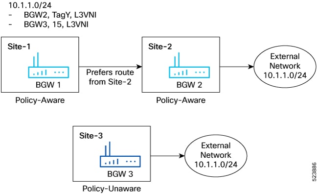
Figure 3. Policy-Aware and Policy-Unaware Tag Next-Hop Preference
In the figure, BGW 1 and BGW 2 are part of policy aware sites and BGW 3 belongs to a policy unaware site. External network
10.1.1.0/24 is advertised from Site 3 and Site 2 to Site 1. Since Site-2 is policy-aware, Route 10.1.1.0/24 is advertised
with “TagY”, which is configured on Site2. Site-3 is policy-unaware, so the route advertised from BGW3 would not carry any
policy information and would be locally assigned to have the default Policy-unaware tag which is ‘15’ when received by BGW1.
On BGW1, the Route would have overlay ECMP of BGW2 and BGW3 with tags of TagY and, ‘15’ respectively. However, since TagY
is a valid tag from the policy-aware site, 10.1.1.0/24 is programmed with Tag ‘TagY’. Similarly, when BGW1 re-originates the
route to a leaf in Site-1, it adds the tag ‘TagY’ to the route.
In a typical Anycast BGW setup, there are no SVI configurations for L2VNIs. However, to support GPO for L2 Bridged IP traffic,
you need to configure an SVI for the L2VNIs on the Anycast BGWs. he SVI configuration does not need an IP Address or the “ip
forward” command. The only requirement is to be configured under the Tenant VRF. This is needed to derive the Tenant VRF information
for Host-IP lookup of the endpoints connected to the L2VNI segment and provide the SGT & DGT tags necessary to enforce the
security policy.
Policy Aware Fabrics in a Multi-Site Domain
This section describes how the route advertisement and packet movement happens between 2 hosts in a policy aware Multi-Site
domain.
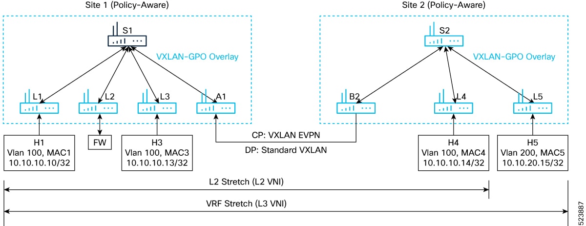
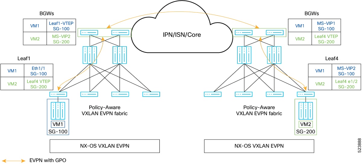
Figure 4. Policy-Aware Multi-site
In the above topology, site 1 and site 2 are policy aware.
Route-advertisement of Host H1 from Leaf L1 to Leaf L5
When a host route H1 is advertised from L1, site 1 to L5 site 2, the route advertisement flow is as follows:
Next-hop Router L1 advertises the route with L1 next-hop and source group tag (TagX) as configured by the policy on router
L1.
Router A1, which is the BGW in the Site-1, re-originates the route with the Multi-Site VIP of the BGW as next-hop, however,
retains the SGT tag (TagX) received from L1.
Similarly, router B2 (BGW in Site-2) re-originates the route H1 inside the local fabric with the Multi-Site VIP of B2 BGW
as next-hop and the same SGT tag (TagX).
Multi-Site receives the route from router B2 and installs it in the forwarding table with the associated security tag “TagX”.
This way, the tag from the originator leaf is retained across the entire multi-site domain.
Refer to the following figure to know about the learned endpoint information on the various nodes.
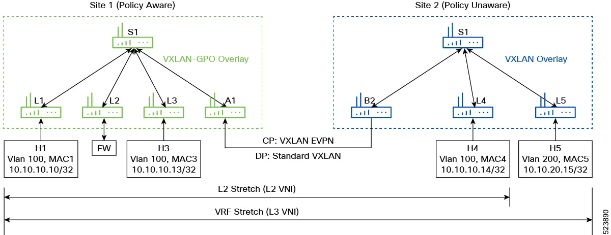
Figure 5. Route Advertisement in a Policy Aware Multi-Site
Packet-Flow from Host H5 to Host H1
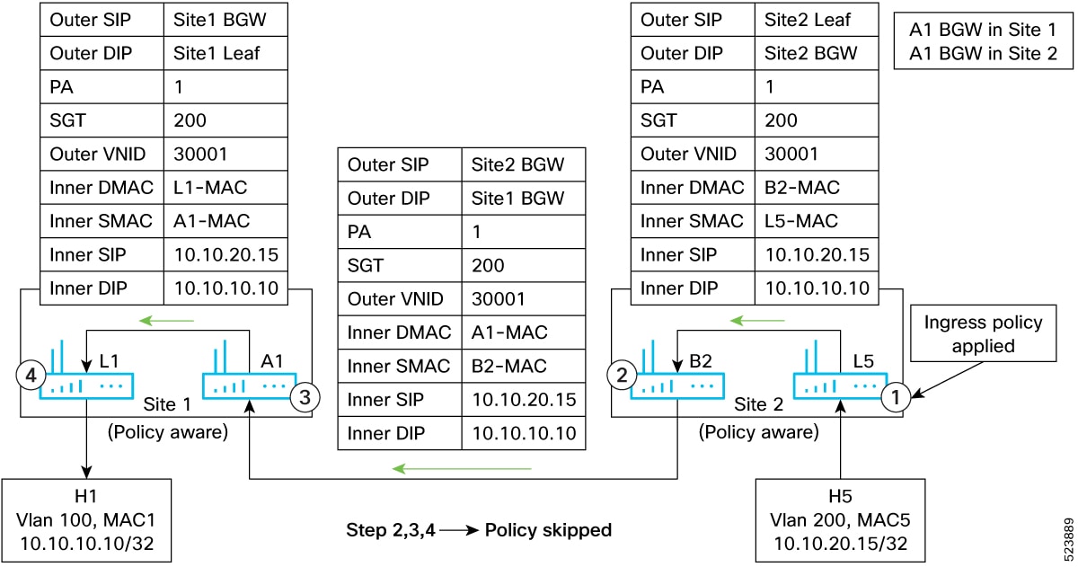
Figure 6. Packet-Flow from Host H5 to Host H1
The packet flow between the hosts H5 and H1 would be as follows.
Router L5 receives the traffic from the host H5. Since both SRC and DST tags are available, L5 would locally apply the security
policy. If the policy-action is permitted, it would set the policy-applied (PA) bit in the VXLAN-GPO header and send the traffic
to BGW router B2, representing the next-hop to reach the destination host H1.
Along with this, the PA bit setting is retained in the VXLAN GPO header B2, on seeing the PA bit set in the VXLAN header,
would not reapply the policy, and just decapsulate and re-encapsulate the traffic sending it to the BGW A1, site 1, representing
the next-hop to reach the destination host H1. Along with this, the PA bit setting is retained in the VXLAN GPO header.
BGW A1 would take a similar action as BGW B2 and forward the traffic to router L1.
Router L1 would not apply Policy as well because of the PA bit set and would forward the traffic to the destination host H1.
Policy Aware and Policy Unaware Fabrics in a Multi-Site Domain
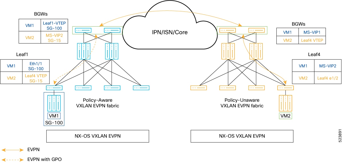
Figure 7. Policy-Aware Policy Unaware Multi-Site
In the above picture, Site-1 is a policy aware site and Site-2 is a policy unaware site.
Route advertisement of Host H1 from Router L1 to Router L5
The route advertisement of Host H1 from router L1 to router L5 would be as follows.
Router L1 advertises the route H1 with next-hop as L1 and SGT Tag (TagY) based on the configuration on L1.
Router A1 locally installs the route with next-hop L1 (and associated tag TagY) and re-originates the route to the remote
BGW B2 with next-hop as A1 Multi-Site VIP and the same SGT Tag (TagY).
The BGW B2, upon receiving the route with SGT Tag (TagY), locally installs the route with A1 as next-hop and ignores the SGT
Tag as it is policy unaware. It then re-originates the route to router L5 with next-hop as B2 Multi-Site VIP.
Router L5 installs the route H1.
Route advertisement of Host H5 from Router L5 to Router L1
The route advertisement of Host H5 from router L5 to router L1 would be as follows.
Router L5 advertises the route for host H5 with next-hop as L5.
BGW B2 locally installs the route with L5 as next-hop and re-originates the prefix with next-hop as B2 Multi-Site VIP.
Since A1 is in a policy aware site, and received the route from a policy unaware fabric, A1 installs the route with the Default
Tag for Policy unaware sites, Tag ‘15’.
BGW router A1 re-originates the route to L1 with next-hop as A1 Multi-Site VIP and Tag 15.
Router L1 installs the route with SGT TAG 15 and next-hop as A1 Multi-Site VIP.
Refer to the following figure to know about the learned endpoint information on the various nodes.
Figure 8. Route Advertisement from a Policy Unaware to Aware Site
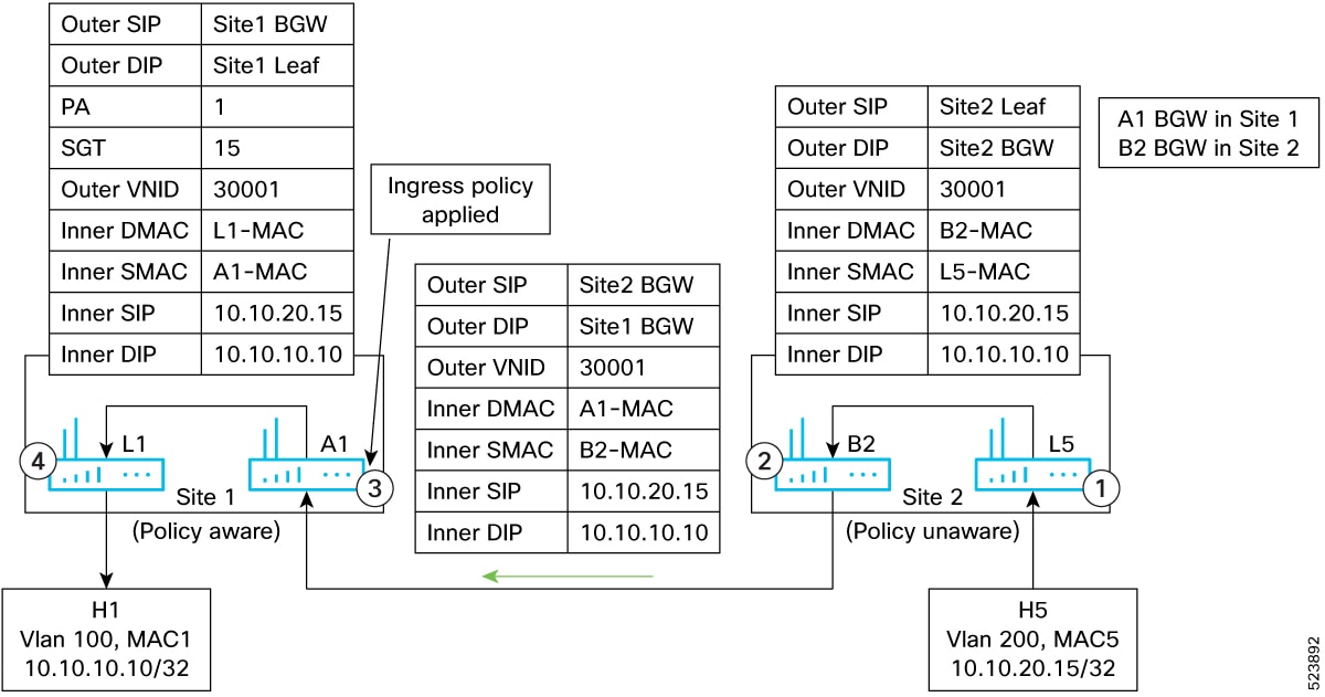
Packet flow from Host H5 to Host H1
Figure 9. Packet flow from Host H5 to Host H1
The packet flow between the hosts H5 and H1 would be as follows.
Router L5 receives the traffic from the host H5 and routes the traffic to B2 with standard VXLAN header.
B2 decapsulates and re-capsulates in a standard VXLAN header.
A1 decapsulates the traffic, applies the policy based on source Tag “15” and destination “Tag Y”. Based on the policy, traffic
is forward to L1 with VXLAN GPO tunnel and policy-applied bit set.
L1 decapsulates the traffic and since PA bit is set, policy is not applied again and forwarded to H1.
Packet flow from Host H1 to Host H5
Packet flow from host H1 to host H5 would be as follows.
Router L1 receives the traffic from H1, applies the policy based on the source Tag ‘TagY’, destination Tag ‘15’. Based on
the policy result, L1 routes the traffic to A1 with VXLAN GPO Tunnel with policy-applied (PA) bit set.
A1 decapsulates and since PA bit is set, it does not reapply the policy and forwards the traffic to B2 in a standard VXLAN
Tunnel.
Traffic flow from B2 to H5 is similar to any Multi-Site deployment.
With the help of micro-segmentation and GPO, NX-OS users can create smaller and isolated segments within a network and enforce
security policies. This allows users to have better control over the traffic flow and apply security policies only where they
are needed.


 Feedback