Cisco Modeling Labs 1.0 Corporate Edition System Administrator Installation Guide
Bias-Free Language
The documentation set for this product strives to use bias-free language. For the purposes of this documentation set, bias-free is defined as language that does not imply discrimination based on age, disability, gender, racial identity, ethnic identity, sexual orientation, socioeconomic status, and intersectionality. Exceptions may be present in the documentation due to language that is hardcoded in the user interfaces of the product software, language used based on RFP documentation, or language that is used by a referenced third-party product. Learn more about how Cisco is using Inclusive Language.
- Updated:
- August 4, 2014
Chapter: Installing the Cisco Modeling Labs Server
Installing the Cisco Modeling Labs Server
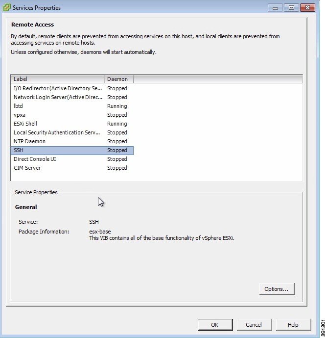
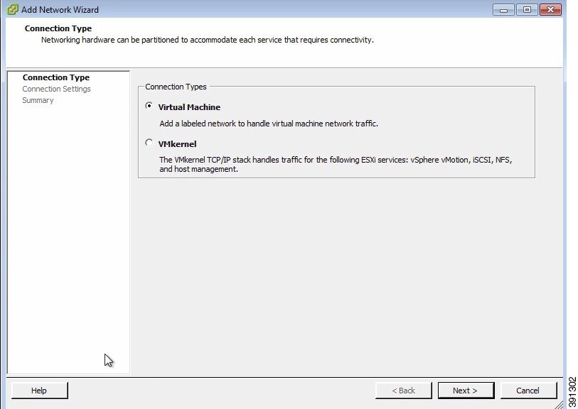
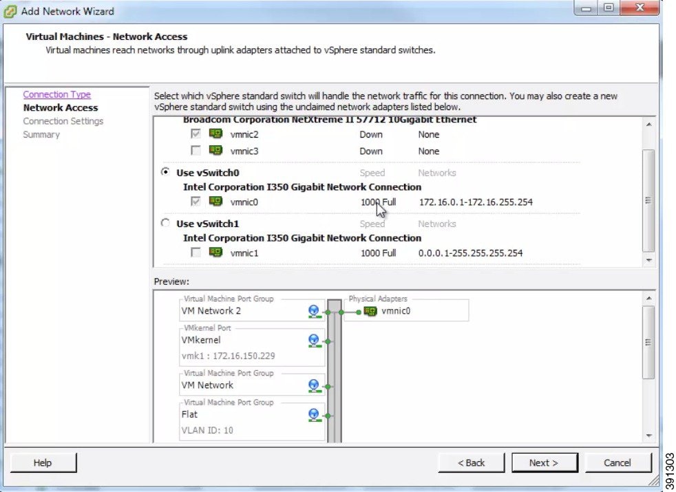
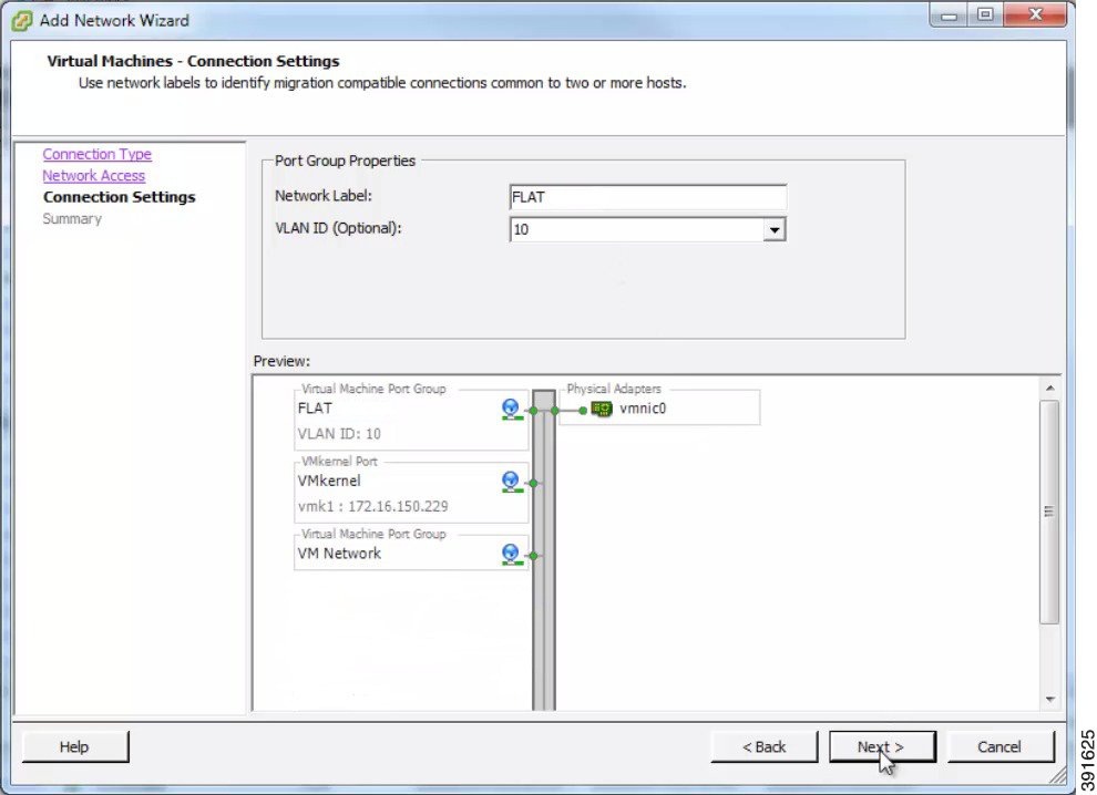
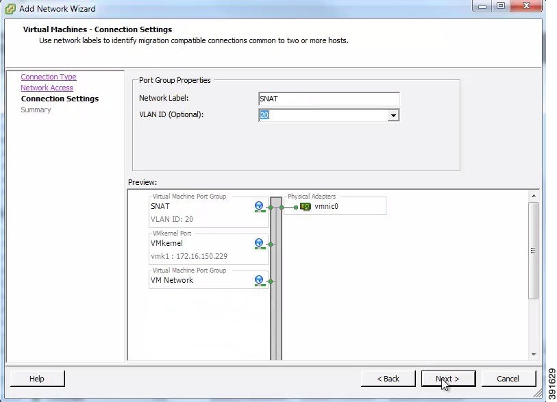
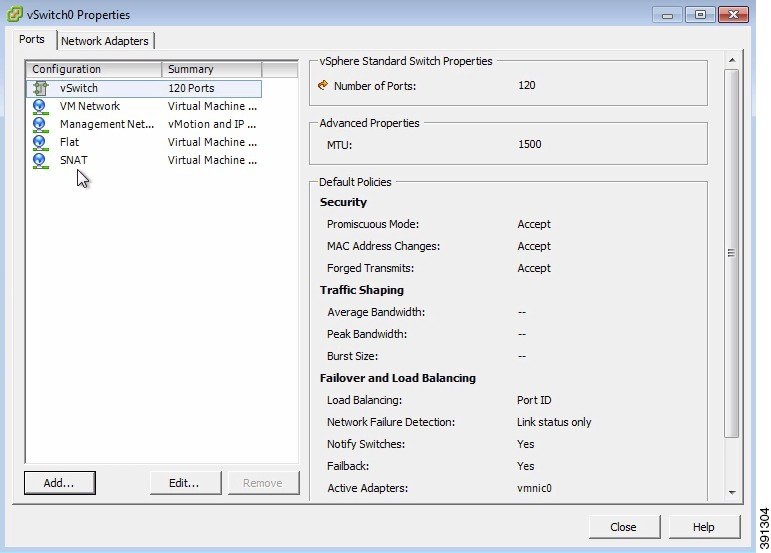
Configuring Security and Network Settings
 Note | When configuring the Cisco Unified Computing System (Cisco UCS) hardware, you must enable Intel Virtualization Technology (Intel VT) in the BIOS for Cisco Modeling Labs 1.0 to operate correctly. |
- Ensure that you have met the requirements as specified in the section Cisco Modeling Labs Server Requirements.
- Ensure that you have administrator access to the ESXi server where you plan to deploy the Cisco Modeling Labs open virtual appliance (OVA), in order to enable nested virtualization.
What to Do Next
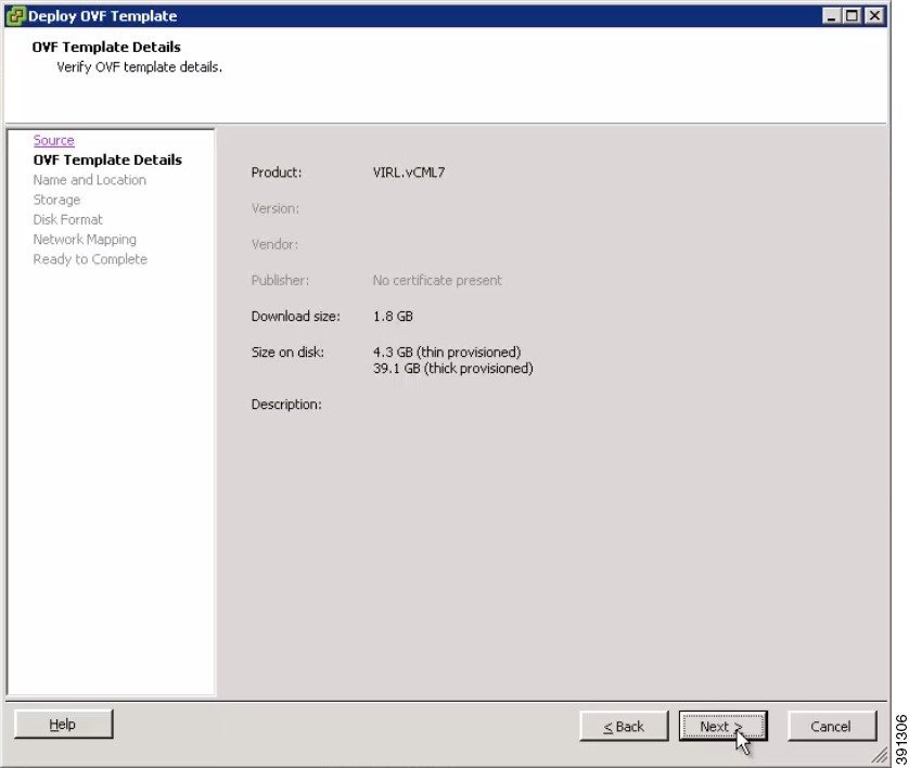
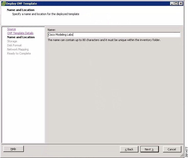
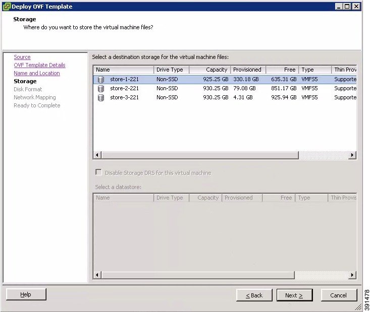
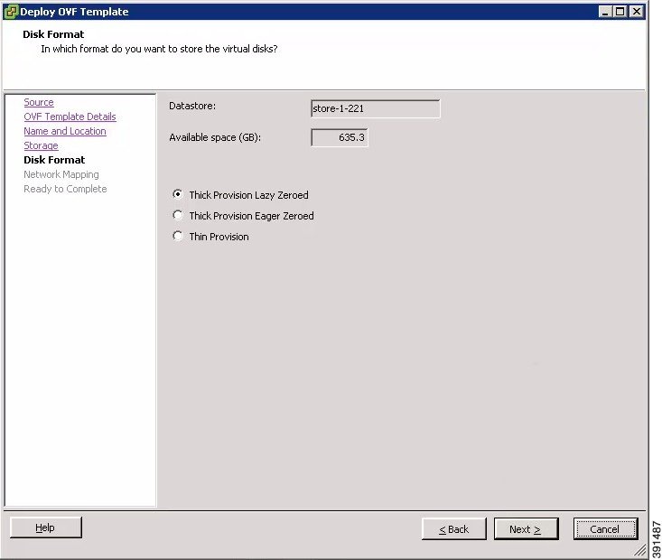
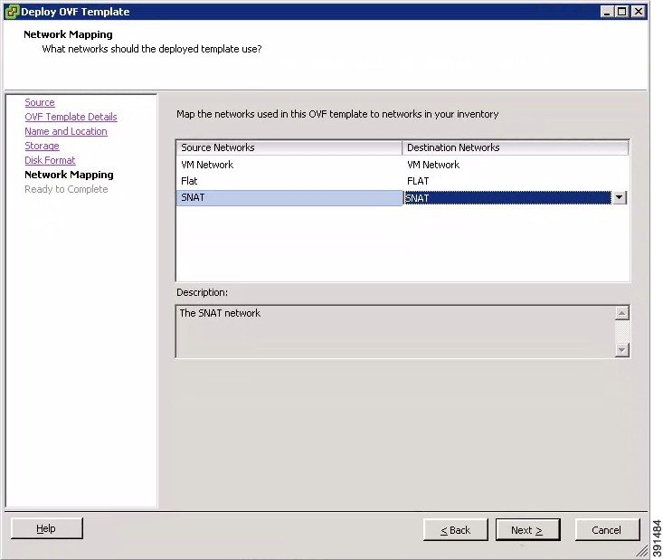
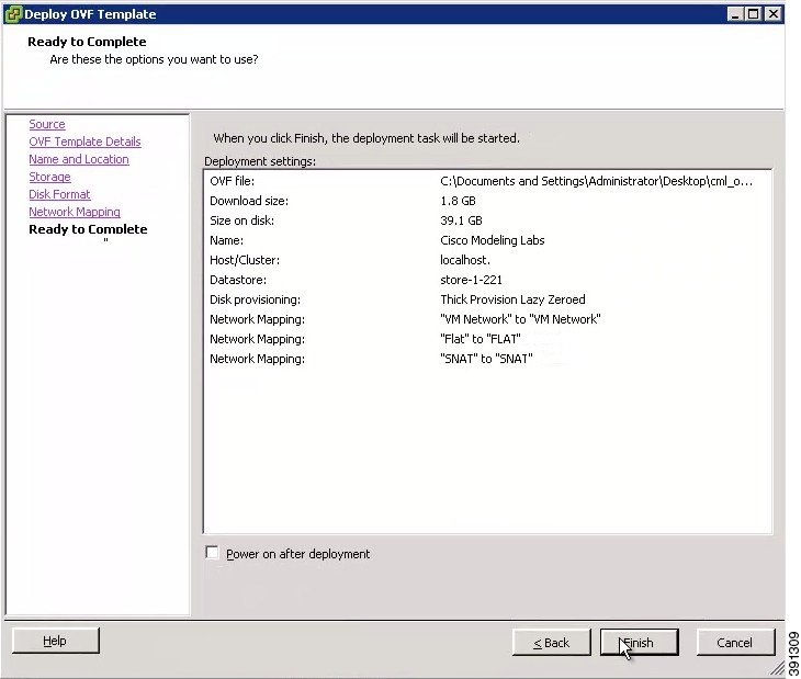
Deploying the Cisco Modeling Labs Open Virtual Appliance (OVA)
What to Do Next
Starting the Cisco Modeling Labs Server for the First Time
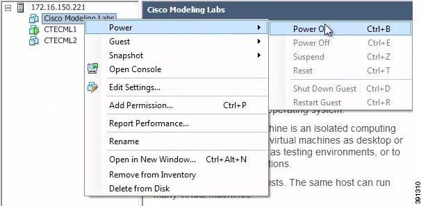
| Step 1 | To power on your
Cisco Modeling Labs server for the first time, choose
in the vSphere client.
 | ||
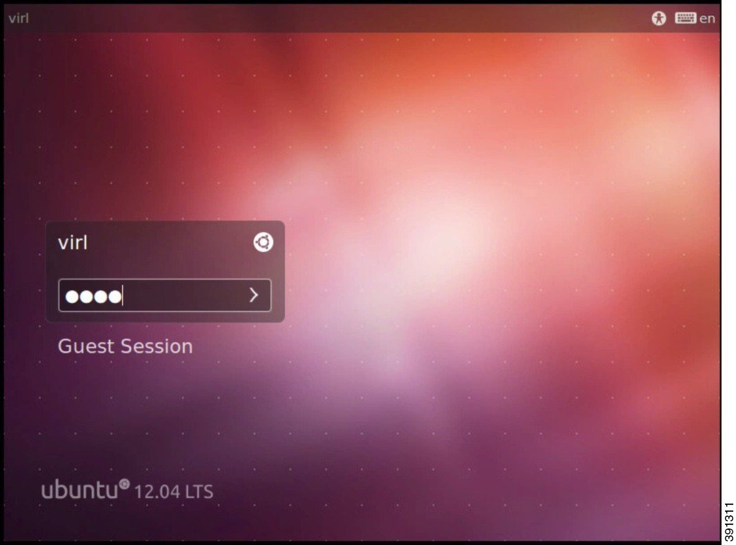
| Step 2 | Under the
Console tab,
log in with the username virl and the password VIRL.
 | ||
| Step 3 | On the desktop, click the xterm icon and enter the CLI command kvm-ok. To ensure that the installation worked correctly, confirm that you received the statement acceleration can be used, indicating that the images will work. There are a number of default settings in the settings.ini file. Values edited in this file are used to configure the Cisco Modeling server for your environment. | ||
| Step 4 | Double-click the 0. Edit settings.ini file icon on the desktop. | ||
| Step 5 | Scroll down the
file and update the following:
| ||
| Step 6 | On the desktop, click the 1. Install networking icon to implement the network changes made in the settings.ini file. | ||
| Step 7 | Click the 2. REBOOT icon to reboot the virtual machine. | ||
| Step 8 | Log in again with the username virl and the password VIRL. | ||
| Step 9 | On the desktop, click the 3. Install changes icon to perform the remaining updates in the settings.ini file now that the network is configured. | ||
| Step 10 | Click the 4. REBOOT icon to reboot the virtual machine. | ||
| Step 11 | Log in with the username virl and the password VIRL. | ||
| Step 12 | Enter the command
ifconfig eth0
to view the IP address assigned.
|
What to Do Next
Access User Workspace Management to determine your Cisco Modeling Labs server hostname and Mac Address values required for license key registration. See Determining License Key Requirements.
Determining License Key Requirements
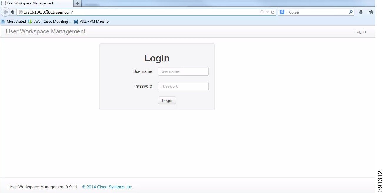
| Step 1 | In a Web browser,
use the IP address or hostname of your Cisco Modeling Labs server to access the
User Workspace Management interface with the username uwmadmin and the password
password, and then switch to
Admin mode.
 | ||||||||
| Step 2 | In the left pane, click Licenses. | ||||||||
| Step 3 | In the Licenses page, click Register Licenses. | ||||||||
| Step 4 | Record the
Host Name and
Mac Address for
license key registration.
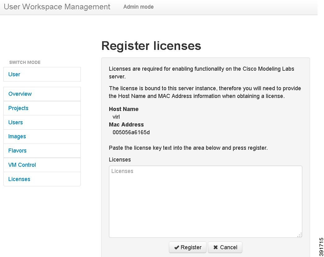 Use this information when completing the Register Claim Certificates instructions in the eDelivery Order Notification email to request your license key for use with the Cisco Modeling Labs server.
You will receive your license key as an attachment via an email. | ||||||||
| Step 5 | Open the attachment in a text editor and copy all the details. | ||||||||
| Step 6 | Return to the Register Licenses page. | ||||||||
| Step 7 | Repeat Step 1 and Step 2, and paste the details into the Licenses text area. | ||||||||
| Step 8 | Click
Register to
register the license key.
| ||||||||
| Step 9 | Click Log out to exit the User Workspace Management interface. |
What to Do Next
Provide end-users with details for accessing the Cisco Modeling Labs client software. See Cisco Modeling Labs Accessibility Requirements.
Cisco Modeling Labs Accessibility Requirements
As system administrator, you must provide the following information to end users so that they can access and use Cisco Modeling Labs 1.0:
- The IP address or hostname of the Cisco Modeling Labs server.
-
The IP addresses of the default gateways for FLAT and SNAT. - FLAT—This is the L2 gateway address that is in the settings.ini file.
- SNAT—See Determining the Default Gateway IP Address for a SNAT Router for information on how to do this.
- Individual username and password details for each end user connecting to the Cisco Modeling Labs server. See the section "Managing Users" for information on creating new users.
- The URL for downloading the Cisco Modeling Labs client software.
- The Web Services port number (applicable only if the default port number has changed).
- The AutoNetkit Visualization port number (applicable only if the default port number has changed).
Note | See the Cisco Modeling Labs 1.0 Corporate Edition Client Installation Guide for detailed information on installing the Cisco Modeling Labs client software. |
Determining the Default Gateway IP Address for a SNAT Router
Note | The SNAT router IP address is statically defined. It is only reset when a project is deleted; in which case, it is removed. |
To determine the IP address for a SNAT router, complete the following steps:
| Step 1 | Log in to the Cisco Modeling Labs server. | ||
| Step 2 | Enter the neutron net-list command to verify that the targeted SNAT project(s) appear. This command lists all of the active networks on the Cisco Modeling Labs server. Each project is automatically assigned a SNAT network. The format is <project name>_snat. Verify that the project is active and that it has a corresponding SNAT network. | ||
| Step 3 | Enter the
neutron
router-list command to locate the unique identifier (ID) for the SNAT
router for the targeted project. Take note of this identifier as you will need
it to run the next series of commands.
| ||
| Step 4 | Enter the neutron router-show <id> command to verify that the router for the targeted project is ACTIVE. The id you enter is the string displayed next to the project name for the network_id field. You should see that the status field for the demo SNAT router is ACTIVE. | ||
| Step 5 | To determine
which IP address on the SNAT router will act as the gateway, first determine
the full list of ports on the SNAT router for the targeted project by entering
the
neutron
router-port-list <id> command, where id is the id field from the list
displayed from the neutron router-show <id> command.
| ||
| Step 6 | To determine which one is assigned to the SNAT router and will therefore be used by the end users as the default gateway in their nodes, enter the neutron subnet-show <id> command for each port until you see one that has the name format of <project name>_snat, for example, demo_snat. This is the default gateway IP address to provide to your end users. |
 Feedback