LAN Automation: Step-by-Step Deployment
Cisco LAN automation simplifies network operations; frees IT staff from time-consuming, repetitive network configuration tasks; and creates a standard, error-free underlay network. LAN automation accelerates building the underlay network without the traditional network planning and implementation process.
This guide is based on Catalyst Center Release 2.3.3; however, an additional topic in the guide provides some information on the LAN automation process based on Catalyst Center Release 2.3.5 and later.
 Note |
Cisco DNA Center has been rebranded as Catalyst Center. During the rebranding process, you will see both names used in different collaterals, but both names refer to the same product. |
The steps and examples may vary based on your Catalyst Center version. For more information on configuring LAN automation and related features, see Cisco Catalyst Center User Guide.
Workflow
Cisco LAN automation provides the following key benefits:
-
Zero-touch provisioning: Network devices are dynamically discovered, onboarded, and automated from their factory-default state to fully integrated in the network.
-
End-to-end topology: Dynamic discovery of new network systems and their physical connectivity can be modeled and programmed. These new systems can be automated with Layer 3 IP addressing and routing protocols to dynamically build end-to-end routing topologies.
-
Resilience: Cisco LAN automation integrates system and network configuration parameters that optimize forwarding topologies and redundancy. Cisco LAN automation enables system-level redundancy and automates best practices to enable best-in-class resiliency during planned or unplanned network outages.
-
Security: Cisco-recommended network access and infrastructure protection parameters are automated, providing security from the initial deployment.
-
Compliance: LAN automation helps eliminate human errors, misconfigurations, and inconsistent rules and settings that drain IT resources. During new system onboarding, LAN automation provides compliance across the network infrastructure by automating globally managed parameters from Catalyst Center.
In four main steps, the Cisco LAN automation workflow helps enterprise IT administrators prepare, plan, and automate greenfield networks:
Procedure
|
Step 1 |
Plan: Understand the different roles in the LAN automation domain. Plan the site and IP pool and understand the prerequisites for seed devices. |
|
Step 2 |
Design: Design and build global sites. Configure global network services and site-level network services. Configure global device credentials. Design the global IP address pool and assign the LAN automation pool. |
|
Step 3 |
Discover: Discover seed devices. |
|
Step 4 |
Provision: Start and stop LAN automation:
|
Step 1: Plan
LAN automation planning is the first step in successfully building the underlay network. This section explains the aspects you must plan to ensure that the Cisco LAN automation support matrix aligns with the targeted underlay network environment.
System Roles
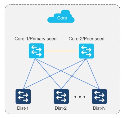
Seed Device
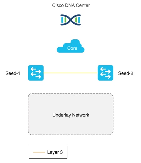
The seed device is a predeployed system in the network and is the initial point through which Cisco LAN automation discovers and onboards new switches downstream. The seed device can be automated through technologies such as Cisco Plug n Play (PnP) and zero-touch provisioning, or configured manually. The following figure shows the seed device network boundaries between the Catalyst Center connection in the IP core and the to-be-discovered underlay network using LAN automation.
The peer seed (Seed-2 in the following figure) can also be automated via LAN automation. Only one seed device is required.
Device discovery happens only on the primary seed device interfaces.
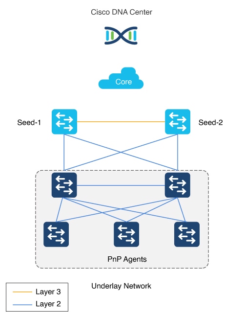
PnP Agent
The PnP agent is a Cisco Catalyst switch with factory-default settings. The switch leverages the built-in day-0 mechanism to communicate with Catalyst Center and support the integrated PnP server function. Catalyst Center dynamically builds the PnP profile and configuration sets that enable complete day-0 automation. The following figure shows the PnP agent physical connection to the seed device.
Automation Boundary
In general, we recommend building structured and hierarchical network designs in enterprise networks to provide scalability and redundancy at every network tier. While the three-tier architecture is proven in large-scale enterprise campus networks, the network design varies based on the overall network size, physical connections, and so on. As part of the initial planning, the network admin must determine the physical topology to automate with Cisco LAN automation.
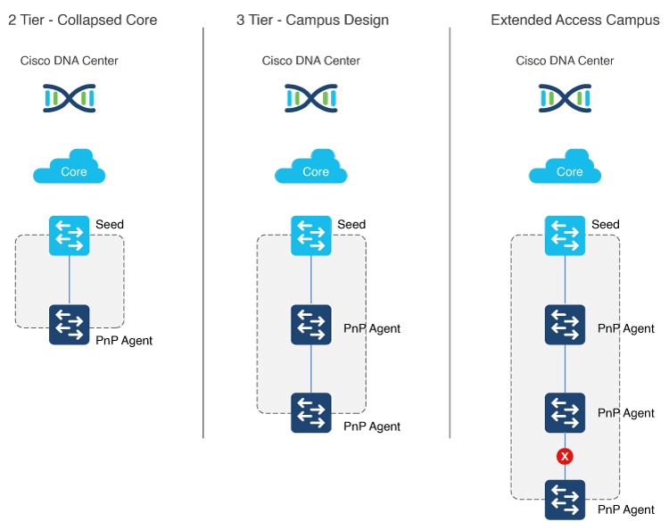
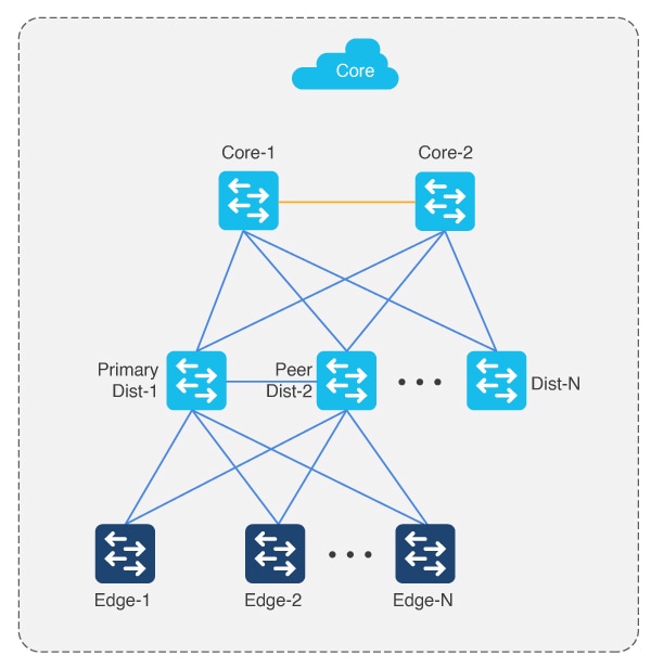
LAN automation in Catalyst Center supports a maximum of two hops from the initial automation boundary point device. In other words, to build the underlay network up to the access layer, the network admin must start the automation boundary from the core or distribution layer. Any additional network devices beyond two hops might be discovered but cannot be automated.
LAN automation initiates only on directly connected neighbors. Consider two scenarios:
-
Scenario 1: You have a three-tier network and you want to LAN automate distribution- and access-layer switches. Because distribution-layer switches (which are directly connected to the seed) participate in LAN automation, both distribution- and access-layer switches will be discovered and LAN automated.
-
Scenario 2: You have a three-tier network and you want to LAN automate distribution- and access-layer switches. You already LAN automated the distribution layer. Later, you add access-layer switches to your network and you want to LAN automate these switches. Because the distribution switches are already LAN automated and links converted to Layer 3, Tier 1 switches cannot be used as the seed. You must choose distribution as the seed in this scenario.
The following figure shows the automation boundary that Cisco LAN automation supports.
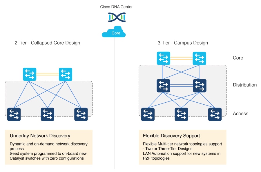
The following figure shows a two-tier and three-tier network design.
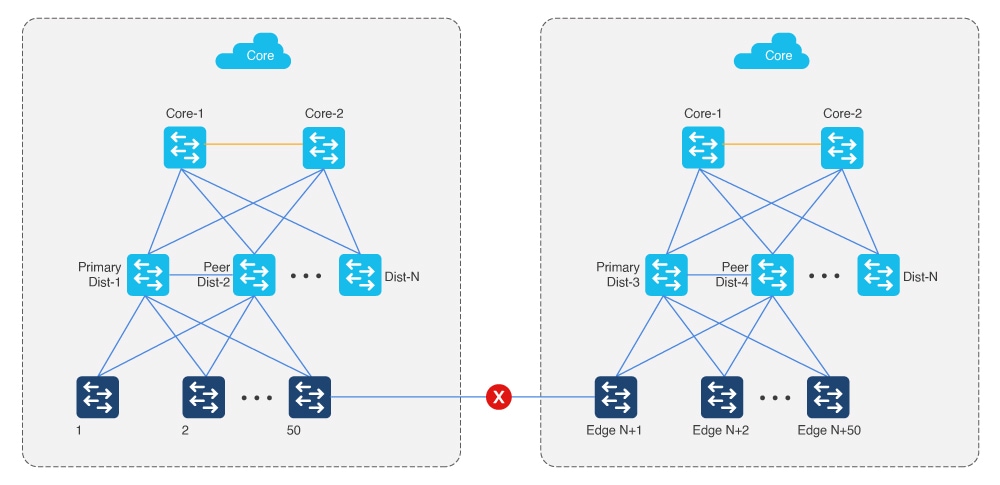
Multistep LAN Automation for Large Topologies: First Pass
Large topologies are brought up by performing LAN automation multiple times. During the first pass, distribution switches are brought up by choosing core devices as seed devices; the distribution switches come up as new devices.
Note |
N is less than or equal to 50 devices at a time. All switches in the group can be booted in parallel or in a staggered fashion. |
Multistep LAN Automation for Large Topologies: Second Pass with First Group
During the second pass, two of the distribution switches act as seed devices to bring up the edge devices as new devices. All new devices in this session must connect directly to the two distribution switches that act as seed devices. Repeat this process for the remaining set of distribution switches, two at a time.
-
Repeat the second pass for each set of distribution to bring up the access/edge switches (where N is less than or equal to 50 devices at a time).
-
Connect uplinks from edges to the primary and peer distribution switches only.
-
Power down IOT/extended devices during the LAN automation session.
-
Distribution switches can be connected to other distribution switches.
-
There can be two tiers of devices below the seeds.
-
Always connect new devices to the primary seed device. Connection to the peer seed device is optional.
Multistep LAN Automation for Large Topologies: Second Pass with Second Group
Edge devices in one group cannot be connected to edge devices in another group. Newly discovered PnP devices in the LAN automation session cannot be connected to existing nonseed inventory devices.
Note |
In Catalyst Center 2.3.5 and later, you can establish links between the devices after LAN automation stops using the Add Link feature. For more information, see Create Link Between Interfaces. |
Link Configuration
-
After all devices are added to the Catalyst Center inventory, you begin the process of Layer 3 link configuration by “stopping” the LAN automation session on the GUI.
-
If you accidentally stop the LAN automation prematurely before all PnP devices are added to the Catalyst Center inventory, links are not configured on in-progress devices. You must delete the in-progress devices from the inventory, begin a new LAN automation session, bring the in-progress devices to the factory-default state, and reload the devices to rediscover them and get their links configured.
-
This process starts the conversion of Layer 2 links to Layer 3 links, which is done by traversing the network graph built during new device onboarding. First, the lower device link is converted to a Layer 3 IP address. Next, the upper device link is converted to a Layer 3 IP address. Router IS-IS configuration is also performed during this step in the connecting links. During this phase, there might be a temporary loss of connectivity to the lower-tier device until the upper-tier link is configured. This phase can also result in an STP topology change when the Layer 2 links are converted to Layer 3.
-
The process follows an algorithm that begins with the tier-three devices, followed by the tier-two devices, and completes with the tier-one devices.
-
It is important to note that only the links between devices that participate in the current session are converted to Layer 3 links. Links between the newly discovered PnP device and the existing nonseed inventory device are not converted to Layer 3.
-
Consider the following scenarios when a LAN-automated device is deleted from the inventory:
-
Scenario 1: If the edge device is single-homed (connected to only one intermediate node) and the intermediate node is deleted from the inventory, then the /31 point-to-point link IP address is deleted from Catalyst Center (IPAM) but may not be unconfigured from the edge device, which is still in the inventory. This is because the edge device can become unreachable from Catalyst Center due to the point-to-point interface between the intermediate node and the fabric border being unconfigured before the one on the edge device. In this case, log in to the edge device CLI and set the interface connected to the deleted device to default configuration. This avoids duplicate IP address assignment during LAN automation workflows later due to the released IP addresses still being present on the device. You can later use the LAN automation workflow to add a new link from the edge device to the new intermediate node or border node (as required) instead of manually configuring the IP addresses.
-
Scenario 2: If the edge device is dual-homed (connected to two intermediate nodes) and one of the intermediate nodes is deleted from the inventory, then the /31 point-to-point link IP address is deleted from Catalyst Center (IPAM) and is unconfigured from the edge device as well. There is no manual configuration required on the edge devices.
-
Catalyst Center 2.3.5 and later provide the support for day-n link configurations (add and delete link). For more information, see Create Link Between Interfaces.
Constraints
-
LAN automation does not automate the onboarding of a StackWise Virtual (SVL) switch via PnP. SVL switch can only be used as a seed device.
-
LAN automation does not support stack renumbering.
-
For platform support, see Supported Switches for Each Role at Different Layers.
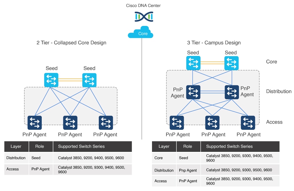
Supported Switches for Each Role at Different Layers
The following figure shows supported device families for the seed and PnP agent at different layers.
Cisco LAN Automation Product Support Matrix
| Role1 | Product Model2 | Network Module3 |
|---|---|---|
|
Seed PnP agent |
C9606R C9600-SUP-1 C9600-SUP-1/2 C9600X-SUP-2 |
Seed: any uplinks and module ports are supported PnP agent: 100G interfaces are not supported |
|
Seed PnP agent |
C9500-32C C9500-32QC C9500-24Y4C C9500-48Y4C C9500X-28C8D |
— |
|
Seed PnP agent |
C9500-12Q C9500-24Q C9500-40X C9500-16X |
Any front-panel ports4 |
|
Seed PnP agent |
C9404R C9407R C9410R |
Sup-15 Sup-1XL3 Sup-1XL-Y3 Any line card |
|
Seed PnP agent |
C9400-SUP-1 C9400-SUP-1XL C9400-SUP-1XL-Y C9400X-SUP-2XL C9400X-SUP-2 |
— |
|
Seed PnP agent |
C9300-24S C9300-24T C9300-24P C9300-24U C9300-24H C9300-48S C9300-48T C9300-48P C9300-48U C9300-48H C9300-24UX C9300-24UXB C9300-24UB C9300-48UXM C9300-48UN C9300-48UB C9300L-48UXG C9300L-24UXG C9300L-24P C9300L-48P C9300L-48T C9300L-24T C9300LM-48UX-4Y C9300LM-48U-4Y C9300LM-24U-4Y C9300LM-48T-4Y C9300X-12Y C9300X-24Y C9300X-24HX C9300X-48HXN C9300X-48HX C9300X-48TX |
Any uplinks and module ports |
|
Seed PnP agent |
C9200-24T C9200-24P C9200-24PB C9200-48T C9200-48P C9200-48PB C9200-48PL C9200-24PXG C9200-48PXG C9200L-24T C9200L-24P C9200L-48T C9200L-48P C9200L-48PL C9200L-24PXG C9200L-48PXG C9200CX-12T-2X2G C9200CX-12P-2X2G C9200CX-8P-2X2G |
Any uplinks and module ports |
|
Seed PnP agent |
WS-C3850-24T WS-C3850-48T WS-C3850-24P WS-C3850-48P WS-C3850-48F WS-C3850-24U WS-C3850-48U WS-C3850-24XU WS-C3850-12X48U WS-C3850-12S WS-C3850-24S WS-C3850-12XS WS-C3850-24XS WS-C3850-48XS |
Any uplinks and module ports |
Site Planning
Use the Catalyst Center Design application to create the required sites, buildings, and floors. Consider how the primary seed and peer seed will be connected to the new devices—for example, will they all belong to the same site or follow a hierarchy? Consider also how to share IP pools across different sites, buildings, and floors. One option is to have a pool specific to a site. Another option is to share a common LAN pool for all sites in the hierarchy. If the devices are onboarded across multiple LAN automation sessions, ensure that the required IP pools are available across the various sites in the hierarchy.
Note |
After devices are provisioned, the site cannot be changed. For this reason, we recommend that you complete LAN automation before you provision devices. |
IP Pool Planning
IP pools for LAN automation are created by first creating a global pool in Catalyst Center, followed by a site-specific LAN IP pool, which LAN automation allocates internally, as follows:
-
One part of the IP pool is reserved for a temporary DHCP server. The size of this pool depends on the size of the parent LAN pool. For example, if the parent pool is 192.168.10.0/24, a subpool of size /26 is allocated for the DHCP server. If the pool size is larger than /24, the algorithm keeps increasing the size of the DHCP pool, up to a maximum of a /23 subpool (512 IP addresses). Therefore, a /24 pool reserves 64; a /23 pool reserves 128; a /22 pool reserves 256; and anything larger reserves 512 IP addresses for the DHCP server. The minimum pool size to start LAN automation is /25; that reserves /27 or 32 IP addresses for the DHCP pool. This IP pool is reserved temporarily for the duration of the LAN automation discovery session. After the LAN automation discovery session completes, the DHCP pool is released, and the IPs are returned to the LAN pool. Because the DHCP pool is usually the largest contiguous segment of IPs required, the pool should have at least one such segment available. If the pool is too fragmented, it cannot allocate the DHCP pool and the LAN automation session ends with an IP pool allocation error.
-
Another part of the IP pool is reserved internally with a subpool size of /27. This subpool is for allocating single IPs for Loopback0 and Loopback60000 always. Also, two consecutive IPs for point-to-point L3 links are allocated from this subpool if no separate overlapping IP pool is provided. This internally reserved subpool is used throughout the LAN automation sessions for providing IPs as long as it has IPs available. In case the IPs are exhausted, a new /27 subpool is created and IPs are allocated from that subpool. These subpools are released only when all the allocated IPs are released as part of the devices being deleted from Catalyst Center. Otherwise, the subpools remain throughout the process and are not allowed to be removed. Due to this internal subpool allocation logic, the IP pool usage in IPAM counts the subpools instead of the actual IPs allocated to the devices.
-
If a shared or link overlapping IP pool is provided for the point-to-point L3 links, then the subpool of size /27 is reserved internally from the shared pool instead of the main IP pool. The subpools are automatically deleted when all the allocated IPs from the pool are released.
When a dedicated (single) IP pool is used to build the underlay networks, each of the devices discovered via LAN automation gets a unique /31 per interface for point-to-point connection, and a unique /32 for Loopback0 and the underlay multicast.
Link Overlapping IP Pool or shared IP pool is used to optimize the IPv4 addressing in the underlay network by allowing overlapping /31 IP addresses for a multisite deployment. Hosts in different sites can get duplicate IP addresses on the /31 links. The /31s in the underlay are not advertised outside of the fabric site and hence there is no need for them to be unique. However, the /32 loopback needs to be unique to every device, and should be advertised to the global routing table to identify the device in the entire network.
There are two valid roles that a LAN IP pool can have:
-
Link Overlapping IP Pool: A pool with this role is optional for a LAN automation session. If provided, the allocation of IP addresses is only on the point-to-point L3 links.
-
Main IP Pool (Principal IP Address Pool in Catalyst Center 2.3.5 and later) : A pool with this role is mandatory for every LAN automation session. This is the pool that is used for all management-related IP addressing such as loopbacks, multicast, and DHCP. If the Link Overlapping IP Pool is not provided, then the Main IP Pool is the default fallback pool for the L3 links IP addressing.
Note |
When the seed device for LAN automation session is in a different site than the discovered device site, then the same shared IP pool cannot be used with the same seed and different discovered device site. This is to avoid the allocation of duplicate IP to the same seed device. |
IP Pool Usage Example
Imagine you want to LAN automate 10 devices using the same pool, where each device has one link to the primary seed and another link to the secondary.
Consider a 192.168.199.0/24 pool. When LAN automation starts, a /26 pool is reserved for the DHCP addresses. In this example, 192.168.199.1 to 192.168.199.63 are reserved and assigned to VLAN 1 for the 10 devices.
Next, a /27 pool is reserved for loopback addresses. If there is no shared IP pool, then this pool is used for point-to-point links as well. Because there are 10 devices with two links each, a total of 2*10*2 = 40 IP addresses are reserved for point-to-point links and 10 loopback addresses are reserved.
In total, 60 IP addresses are reserved for the 10 devices: 10 for each VLAN 1, 10 for each loopback, and 40 for the point-to-point links between devices and seeds.
After LAN automation stops, the VLAN 1 IP addresses are released back to the pool, and 90 addresses are allocated for the LAN automation session.
Note the following:
-
The same IP pool can be used for multiple discovery sessions. For example, you can run one discovery session and discover the first set of devices. After discovery completes, you can provide the same IP pool for a subsequent LAN automation session. Similarly, you can choose one LAN pool for one discovery session and another LAN pool for a second discovery session.
-
Every time you start LAN automation, it checks for 64 available IP addresses in the IP pool. If you decide to run LAN automation multiple times with the same pool, use at least a /24 pool. If you plan to LAN automate only once for the IP pool, a /25 pool suffices.
-
Don't use an address pool that is in use elsewhere in the network, such as an address pool that belongs to the loopback or to other addresses configured on the device.
Site-Specific CLI and SNMP Configuration
To start LAN automation, a site-specific CLI and SNMPv2 read or SNMPv3 configuration is required. Use the Catalyst Center Design application to configure the site-specific CLI and SNMP. Save the configuration for the site that is used for LAN automation. If you configure the credentials at the global level, they are visible at the site level. You must click the radio button for the specific site and then save the configuration to make it available for LAN automation.
Note |
SNMPv2 write credentials are not required and if configured, it won't be pushed to the device during LAN automation. |
Configuration on Seed Devices
When configuring the seed devices, follow these guidelines:
-
The system maximum transmission unit (MTU) value must be at least 9100.
-
Turn on IP routing on the seed devices.
-
Set up routing between the seed service and Catalyst Center so that Catalyst Center has IP reachability to the LAN IP pool subnet.
-
We recommend that you use the default interfaces connected to PnP agents. If the peer seed device has IP interfaces configured on the interfaces connected to PnP agents, those links don't get configured. If you want to configure the peer device interfaces connected to PnP agents, use the default interfaces and perform an inventory synchronization on the peer seed device. LAN automation works only when the ports are Layer 2. The ports on Cisco Catalyst 6000 are Layer 3 by default. Convert the ports to Layer 2 before starting LAN automation.
-
Configure device credentials and SNMP credentials on the seed devices.
-
If the seed devices have Layer 3 interfaces configured, ensure that there are no conflicts with any of the IP pools provided in Catalyst Center. Check the IP addresses which are configured manually.
-
Ensure that the seed devices don't have any other interfaces connected to another DHCP server running in VLAN 1.
-
If loopback is not configured on the seed devices, LAN automation configures loopback on the seed.
-
If any configuration changes are made on the seed devices before running LAN automation, synchronize the seed devices with the Catalyst Center inventory.
-
Assign the seed devices to a site. (You don't have to provision the seed devices for LAN automation.)
Additional recommended configurations on seed devices:
-
Run multiple discovery sessions for devices across sites connected to the same seed: If you plan to run multiple discovery sessions to onboard devices across different buildings and floors connected to the same seed devices, we recommend that you block the ports for PnP agents that do not participate in the upcoming discovery session.
For example, imagine that seed devices are in Building-23 and are connected to PnP agents on Floor-1 and Floor-2. Floor-1 devices are connected on interfaces Gig 1/0/10 through Gig 1/0/15. Floor-2 devices are connected on interfaces Gig 1/0/16 through Gig 1/0/20. For the discovery session on Floor-1, we recommend that you shut down ports connected to Gig 1/0/16 to Gig 1/0/20. Otherwise, the PnP agents connected to Floor-2 might also get DHCP IPs from the server running on the primary seed device. Because these interfaces aren't selected for the discovery session, they remain as stale entries in the PnP database. When you run the discovery session for Floor-2, the discovery doesn't function correctly until these devices are deleted from the PnP application and write erase/reloaded. Therefore, we recommend that you shut down other discovery interfaces.
-
Endpoint/client integration: For Catalyst Center 1.2.8 and earlier, if there are clients connected to a switch that is being discovered, those clients contend for DHCP IP and might exhaust the pool, causing LAN automation to fail. Therefore, we recommend that you connect the client after LAN automation is complete.
This endpoint/client integration restriction does not apply to Catalyst Center 1.2.10 and later. Clients can remain connected while the switch is undergoing LAN automation.
PnP Agent Initial State
Ensure that the device that you want to LAN automate is running the Advantage license level. Otherwise, some commands are not pushed.
Note |
Catalyst Center 2.3.5 and later support automatic license upgrade for C9000 and C3850 series switches. |
New PnP agents have factory defaults and are ready to start LAN automation.
If you are reusing existing network devices, ensure the following:
-
PnP agents must have the required license that allow you to push the LISP, IS-IS routing, and CTS-related CLI commands. Use the show license command to see the current license level. If required, upgrade the license.
-
PnP agents should not have stale certificate or keys from the previous runs.
-
Restore the switch configurations to factory default using the following commands:
-
For Cisco IOS XE 16.11 and earlier, use:
[CLI config mode]

    no pnp profile pnp-zero-touch
    no crypto pki certificate pool
    Also remove any other crypto certs shown by "show run | inc crypto"
    crypto key zeroize
    config-register 0x2102 or 0x0102 (if not already)
    do write
    end
[CLI exec mode] delete /force nvram:*.cer delete /force stby-nvram:*.cer (if a stack) delete /force flash:pnp-reset-config.cfg write erase reload (enter no if asked to save) -
For Cisco IOS XE 16.12.x or later, use:
[CLI exec mode]

pnp service reset no-prompt
-
Step 2: Design
The design phase is the second step in LAN automation. During the design phase, you:
-
Design and build global sites.
-
Configure global and local network services.
-
Configure global device credentials.
-
Design the global IP address pool and assign the LAN automation pool for the required site from the global pool.
Design and Build a Site
This section explains how to design and build a site.
Procedure
|
Step 1 |
From the Catalyst Center home page, click the menu icon and choose . |
||
|
Step 2 |
Create a site and add buildings and floors.
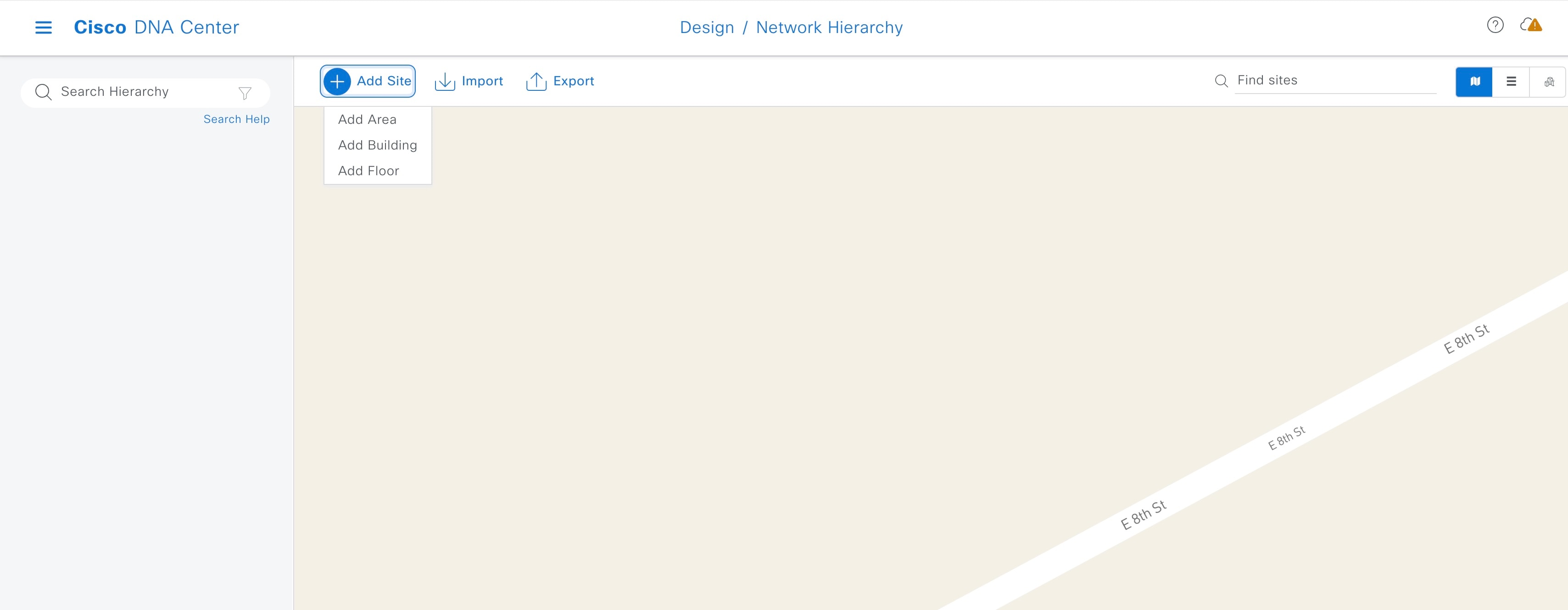
|
||
|
Step 3 |
From the top-left corner, click the menu icon and choose . |
||
|
Step 4 |
Click Manage Credentials and add the following credentials:
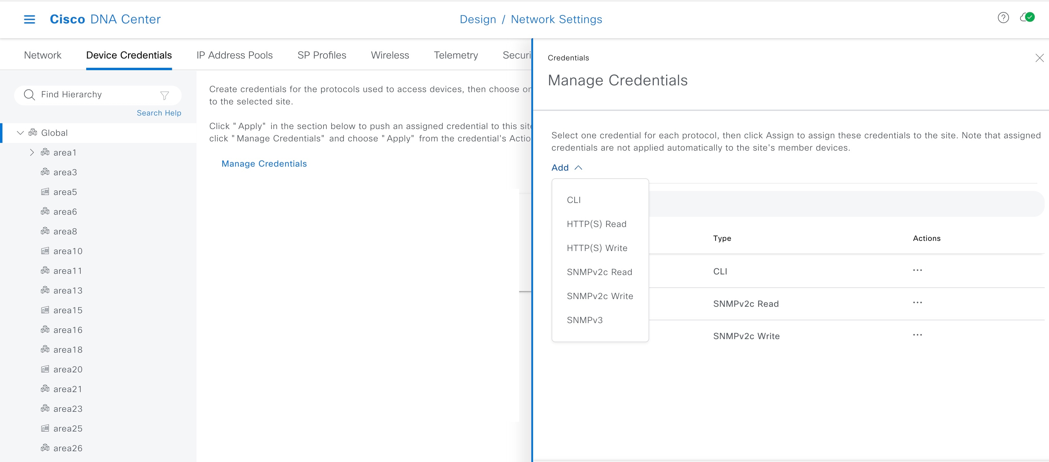
|
||
|
Step 5 |
From the top-left corner, click the menu icon and choose . |
||
|
Step 6 |
From the left hierarchy tree, choose Global and click Add. Create a dedicated IP address pool to use for the underlay infrastructure. Do not use an address pool that is already in use in the network. For example, do not use an address pool that belongs to a loopback or other addresses configured on the device. 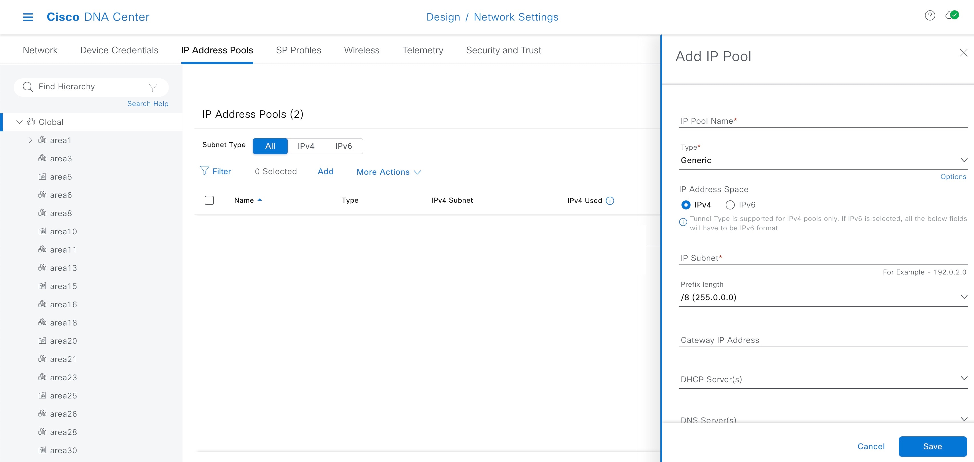
|
||
|
Step 7 |
From the left hierarchy tree, choose a site and click Reserve. |
||
|
Step 8 |
In the Reserve IP Pool window, from the Type drop-down list, choose LAN. 
|
Step 3: Discover
Device discovery is the third step in successfully building the underlay network.
Before creating and running a discovery profile, review the underlay configuration of the seed device.
Create Discovery Profile
This section explains how to create a discovery profile.
Procedure
|
Step 1 |
From the Catalyst Center home page, click the menu icon and choose . |
||
|
Step 2 |
In the Discovery window, click Add Discovery. |
||
|
Step 3 |
In the New Discoverywindow, enter the following details:
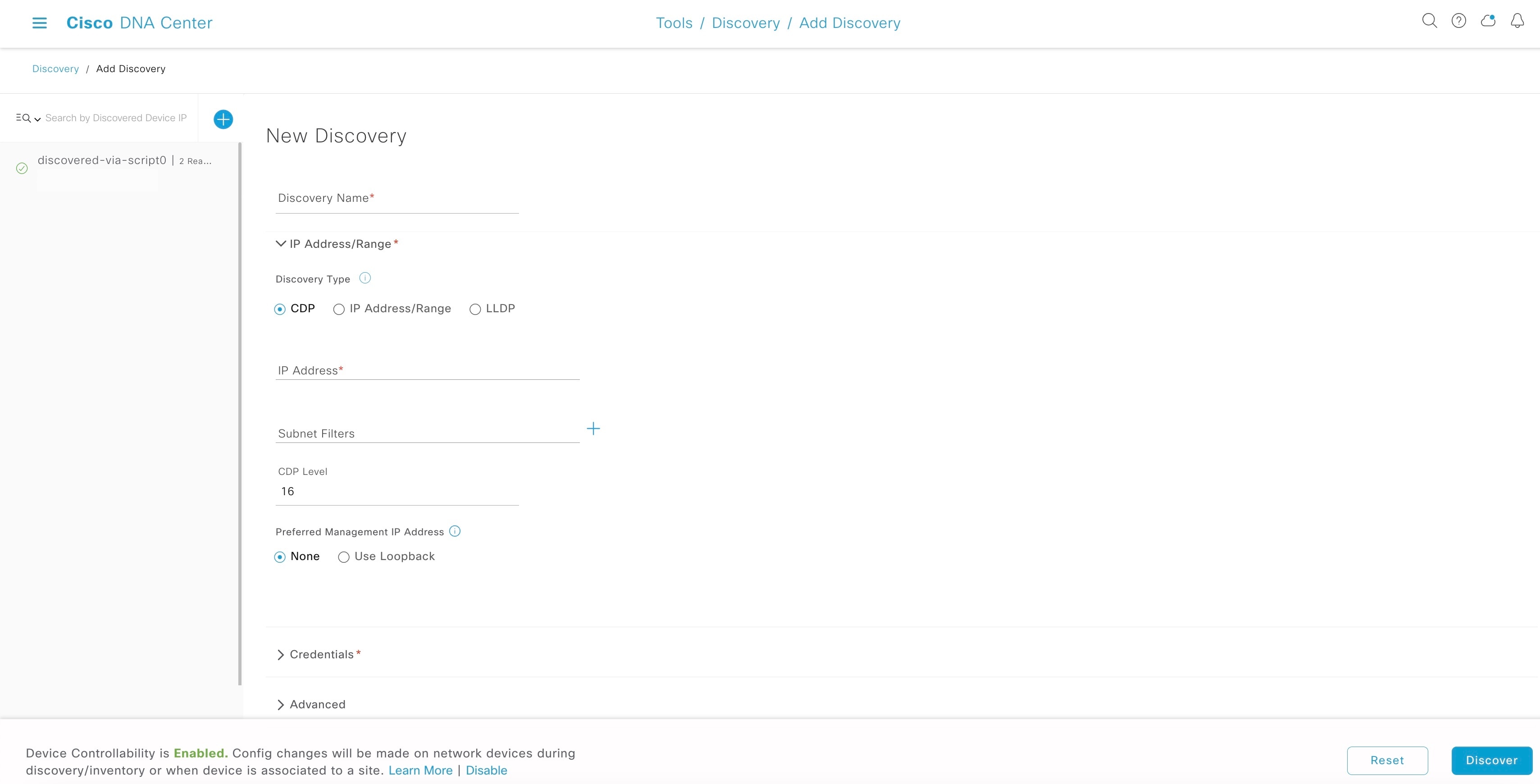
|
||
|
Step 4 |
Click Discover. |
||
|
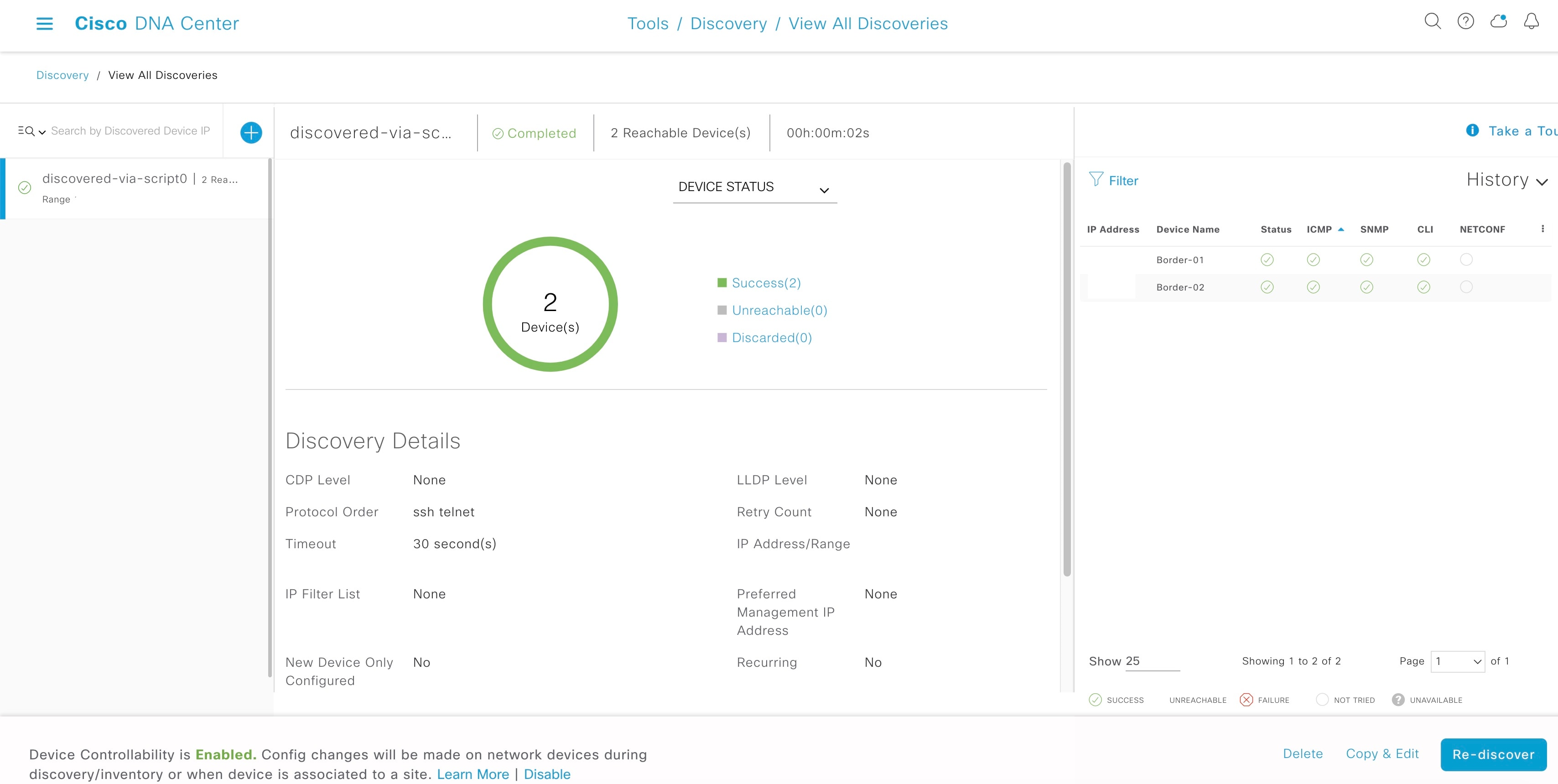
Step 5 |
Choose a discovery schedule and click Start. You can view the status and results of the scan in the Discoveries window.
|
||
|
Step 6 |
To verify that the discovered device is added to the inventory, click the menu icon and choose .
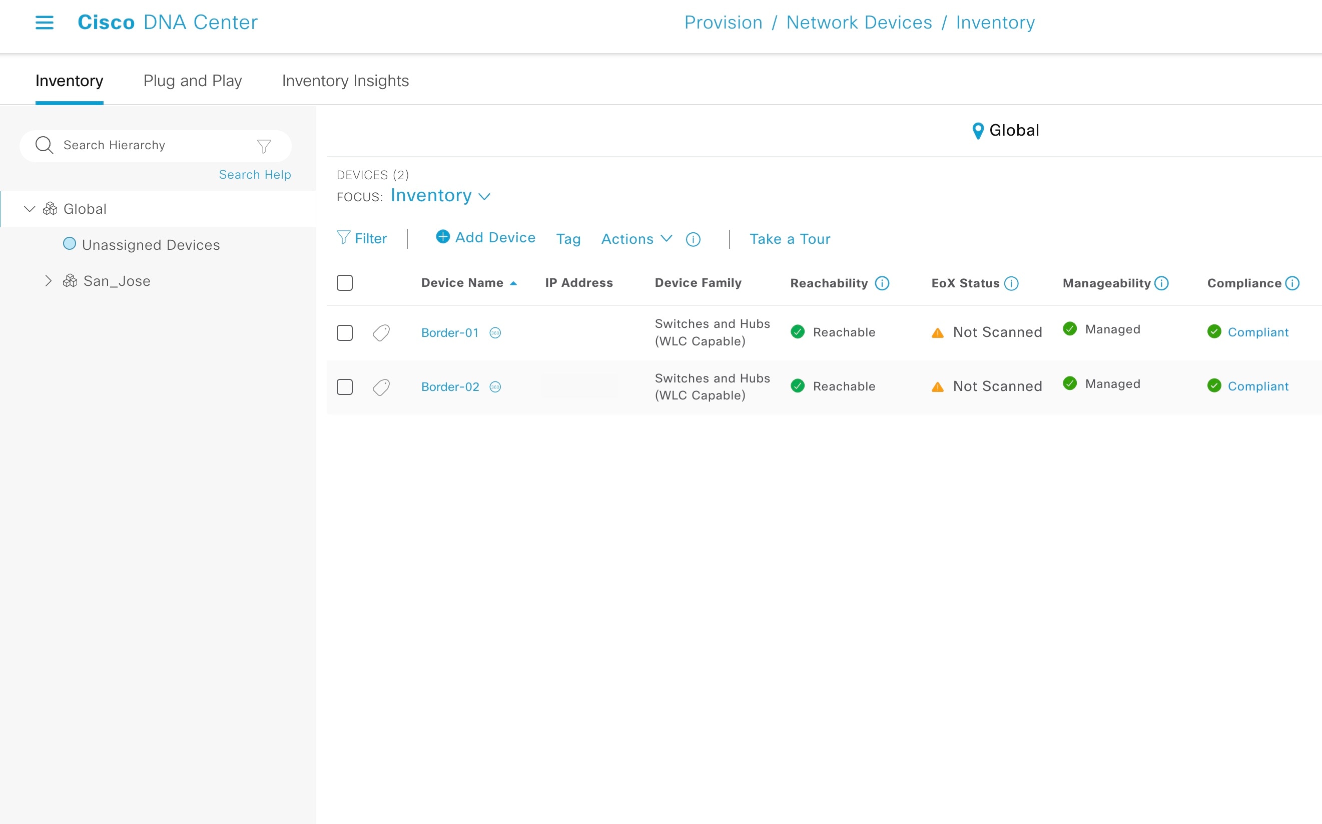
|
||
|
Step 7 |
To assign the device to site from inventory, select the device and from the Actions menu, choose . 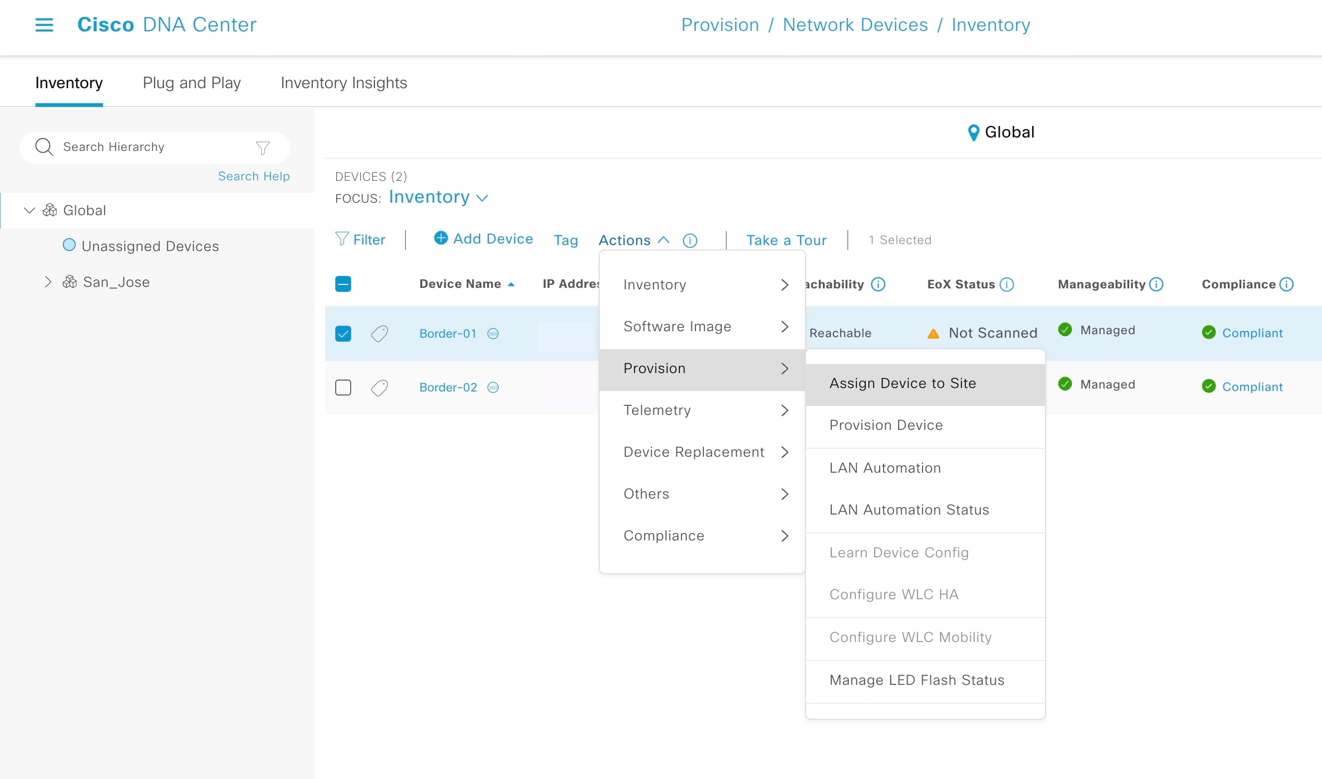
|
||
|
Step 8 |
In the Assign Device to Site window, choose a site and click Apply. For Catalyst Center 1.2.6 and earlier, ensure that both the primary and peer seeds are in the same site and same floor (although they can be physically on different floors). The discovered device is added to the selected site.
|
 , check the
 Steps to Consider Before Starting LAN Automation
Take the following considerations into account before starting the LAN automation process.
IP Pool Subnet Reachability from Catalyst Center
LAN automation discovery uses the LAN pool to reach PnP agents. Catalyst Center should be able to reach the IPs allocated from the LAN pool. For example, if the LAN pool is 192.168.10.0, Catalyst Center should have the correct route to reach this subnet. To test the reachability, create an SVI (VLAN 1 interface) on the primary seed device and do a ping test between Catalyst Center and the seed. Refer to the following sample code.
[On seed device]Switch(config)#interface vlan1
Switch(config-if)#ip address 192.168.99.1 255.255.255.0
Switch(config-if)#end[On Catalyst Center CLI console][Sat Jun 23 05:55:18 UTC] maglev@10.195.192.157
$ ping 192.168.99.1
PING 192.168.99.1 (192.168.99.1) 56(84) bytes of data.
64 bytes from 192.168.99.1: icmp_seq=1 ttl=252 time=0.579 ms
64 bytes from 192.168.99.1: icmp_seq=2 ttl=252 time=0.684 ms
64 bytes from 192.168.99.1: icmp_seq=3 ttl=252 time=0.541 ms[On seed device]Switch(config)#default int vlan 1
Interface Vlan1 set to default configurationIf the ping test fails, the route is not set up correctly on Catalyst Center.
Static Route Addition for LAN Pool
Catalyst Center hardware has multiple physical interfaces with each serving different categories of communication. See the Cisco Digital Network Architecture Center Appliance Installation Guide for recommended interface connections, IP routing, and static assignment. In a single-home design, Catalyst Center performs the host function with the default gateway providing IP routing. In a multi-home design, Catalyst Center must have a static route to the LAN automation networks via the enterprise-facing interface.
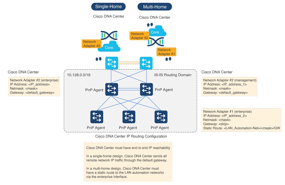
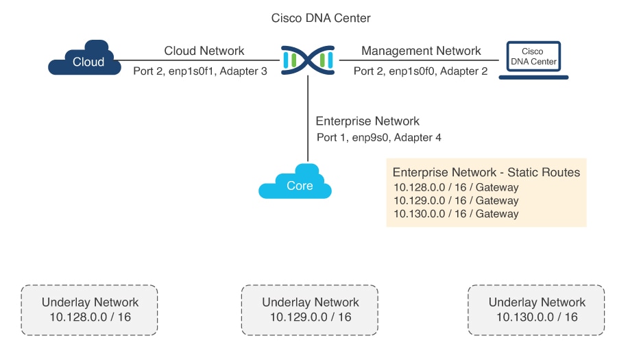
If the network design is a multi-home design, one way to fix the IP reachability issue is to add a static route on Catalyst Center. A network administrator can add a static route during the initial Catalyst Center configuration or later via a maglev command. (Don't use the Linux route command, because maglev APIs don't pick the correct information if the route is modified using the route command.)
For a single-home design, check the routing between the seed and Catalyst Center.
To add a static route on Catalyst Center:
Procedure
|
Step 1 |
On the Catalyst Center console, enter the command 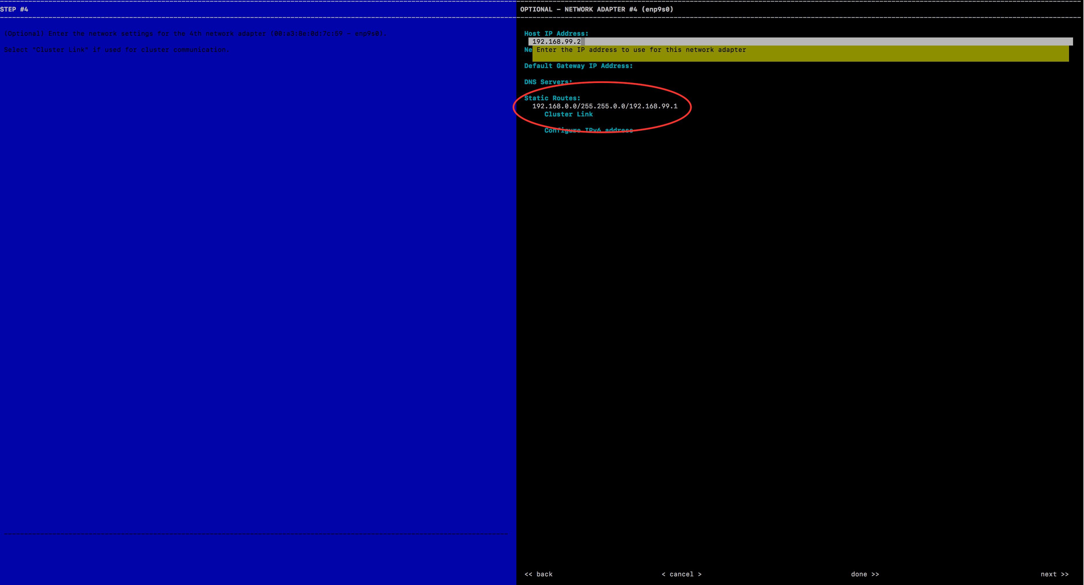 |
|
Step 2 |
Enter the static route and click Next. The config wizard validates and configures host networking. |
|
Step 3 |
Ensure that the correct interface is selected to add the static route. Otherwise, click Next until the correct interface is displayed on which to configure the route. |
|
Step 4 |
Leave the Network Proxy field blank. When the proxy validation fails, skip the proxy settings. |
|
Step 5 |
Click Proceed to apply the changes to the controller. It takes from 5 to 6 minutes to add a static route. You can ignore any warning messages.
|
PnP Agent Initial State Before Starting LAN Automation
Procedure
|
Step 1 |
Before starting LAN automation, make sure that the PnP agent is in System Configuration Dialog state. |
||||
|
Step 2 |
Do not press Yes or No. Leave the device in the same state.
Stack Considerations
|
Unplug the Management Port
Connect PnP agents directly to seed devices. Do not connect PnP agents to any other network (for example, the management network) or any network that can provide DHCP through another server on VLAN 1.
Ensure That Seed Ports Are Layer 2
Ensure that the seed ports connected to the PnP agents are Layer 2 and defaulted. For example, Cisco Catalyst 6500 and 9500H ports are Layer 3 by default.
Ensure That Primary Seed Port Does Not Block STP
Ensure that the port on the primary seed connecting to the PnP agents does not block STP.
Ensure That the Device Is Not Present in Inventory
This section applies to devices that were discovered or LAN automated at any point.
If the devices to discover in an upcoming LAN automation session are already present in the inventory, complete the following steps to remove them from the inventory.
Before you begin
If a device was provisioned and added to the fabric, remove it from the fabric and unprovision it before you remove it from the inventory.
Procedure
|
Step 1 |
From the Catalyst Center home page, click the menu icon and choose . |
|
Step 2 |
Filter the devices by Serial Number and then from the Actions drop-down list, choose . 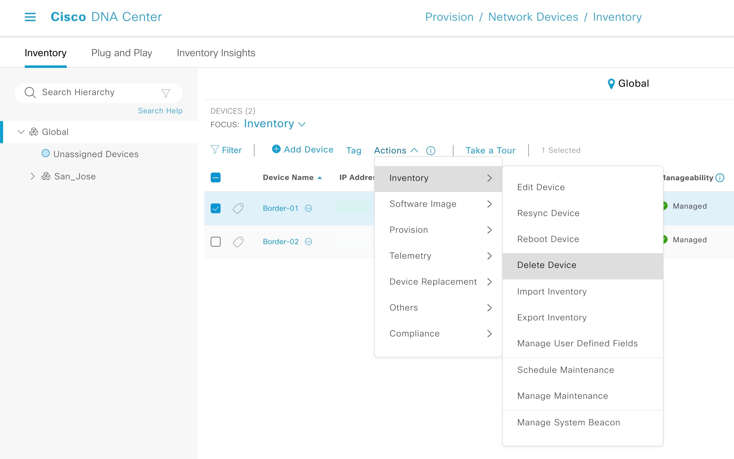
|
Ensure That the Device Is Not Present in PnP
If the devices to discover in an upcoming LAN automation session are already available in PnP, complete the following steps to remove them from PnP before you run the discovery. Otherwise, the discovery won't work correctly.
Procedure
|
Step 1 |
From the Catalyst Center home page, click the menu icon and choose . |
|
Step 2 |
From the Device Status filter, choose Unclaimed. Make sure that the device (Serial Number) being discovered is not available under Unclaimed. 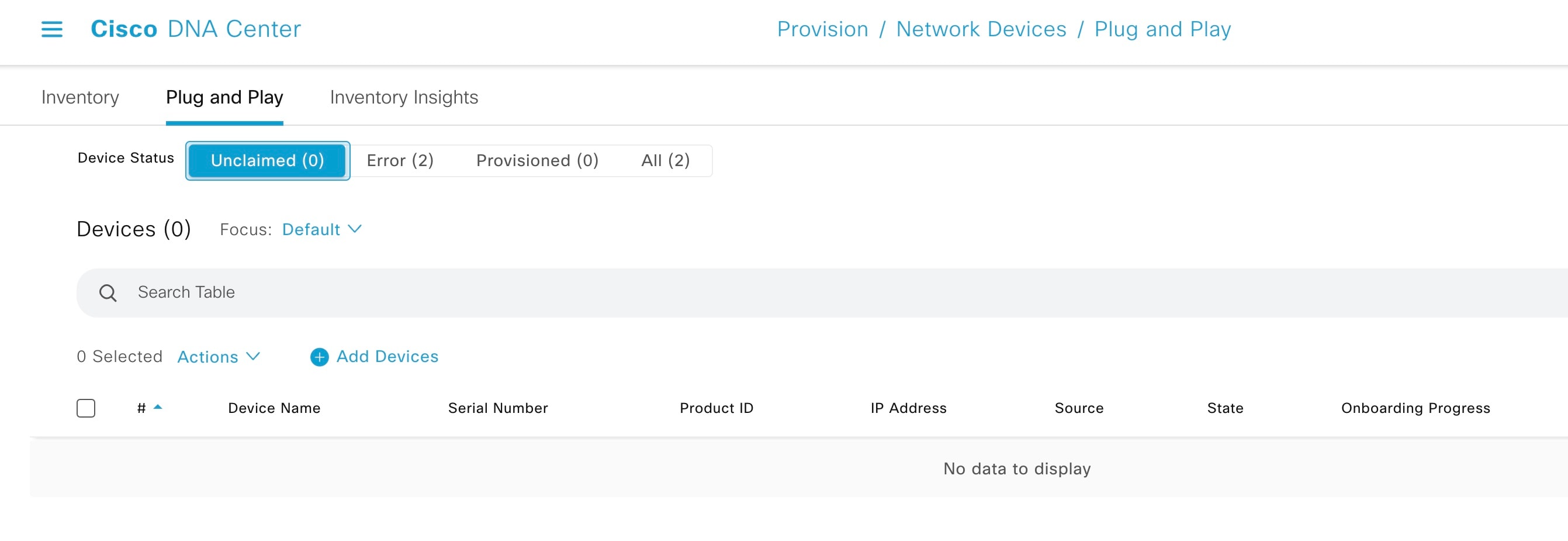
|
|
Step 3 |
If the device is available, console into the device and remove the PnP profile: For Cisco IOS XE 16.12.x or later, use: |
|
Step 4 |
Check the check box of the device in the Unclaimed section and choose . |
Use the Advantage License
Ensure that the PNP agent is running the Advantage license level.
Ensure That the PNP Agent is in INSTALL Mode
For the image upgrade to occur during LAN automation, the PnP agent must be in INSTALL mode.
Image upgrade through LAN automation occurs in the background.
Procedure
|
Step 1 |
After PnP discovers the device, Catalyst Center checks whether any golden image is marked for the switch family (Cisco Catalyst 9300 or 3850) of the discovered device. To check whether a golden image is selected, choose . If the golden image is marked and the discovered device is not running the golden image, LAN automation upgrades the discovered device to the golden image. If not, Catalyst Center skips the image upgrade and proceeds to pushing the initial device configuration. |
|
Step 2 |
If you want LAN automation to upgrade the image on the discovered device, ensure that the device is running in INSTALL mode. Image upgrade through LAN automation does not occur if the device is in BUNDLE mode. |
|
Step 3 |
If the device is in BUNDLE mode and you want to proceed with LAN automation, remove the golden image for that particular switch family . |
Step 4: Provision
Provisioning is the final step in the LAN automation process. It is divided into two stages:
-
Device discovery and onboarding (starting LAN automation).
When LAN automation starts, it:
-
Pushes the loopback and IS-IS configuration to the primary and peer seed devices and the temporary configuration to the primary seed device, enabling discovery and onboarding of the PnP agent.
Note
Catalyst Center 2.3.3 and later support
is-type level-2-onlyas part of IS-IS configurations.
-
Discovers new devices.
-
Upgrades the image and pushes the configuration to discovered devices.
Note
The image is updated only if a golden image is marked for that switch type under the Catalyst Center home page > .
When LAN automation starts, the temporary configuration is pushed to the primary seed device, which discovers and onboards the PNP agent. Next, the PNP agent image is upgraded and basic configurations such as loopback address, system MTU, and IP routing are pushed to the PNP agent.
-
-
Interface configuration (stopping LAN automation).
When LAN automation stops:
-
The discovery phase ends and all point-to-point links between the seed and discovered devices and between the discovered devices (a maximum of two hops) are converted to Layer 3.
-
All temporary DHCP and VLAN 1 configurations on the seed and discovered devices are removed. The DHCP subpool is returned to the LAN automation pool.
-
Start LAN Automation
For LAN automation, you must select the primary seed device, peer seed device, site for seed device, LAN IP pool, and interface. Optionally, you can select the device prefix, hostname CSV file, configurable IS-IS password, and so on.
Interface Selection
Interfaces on the primary seed device participate in the new device discovery and L3 configuration. The interfaces on seed devices provide a filter to directly connect PnP agents that can be onboarded through the LAN automation session. For example, consider four directly connected PnP agents: device-1 through Gig1/0/10, device-2 through Gig 1/0/11, device-3 through Gig 1/0/12, and device-4 through Gig 1/0/13. If you choose Gig 1/0/11 and Gig 1/0/12 as part of the discovery interfaces, LAN automation discovers only device-1 and device-2. If device-3 and device-4 also try to initiate the PnP flow, they are filtered, because they are connected through interfaces that are not selected during the LAN automation session. This mechanism lets you restrict the discovery process.
Interface selection also lets you choose interfaces between the primary seed and the peer seed to configure with Layer 3 links. If there are multiple interfaces between the primary and peer seeds, you can choose to configure any set of these interfaces with Layer 3 links. If no interfaces are chosen, they aren't configured with Layer 3 links.
The option to choose a peer seed interface is not available. Interfaces between peer seed and PnP agents are automatically inferred based on the topology information gathered from the device. The topology information is built on the CDP information available on the device.
Site Selection
Sites can be selected for seed devices and PnP agents. Currently, there is one site for seed device(s) and one site for PnP agents.
LAN Pool Selection
The LAN pool is selected based on PnP agent site information. To start LAN automation, select a LAN pool from the list of LAN pools available for a particular site. You can select the same LAN pool for multiple LAN automation sessions. For example, you can run one discovery session and discover the first set of devices. After the discovery session completes, you can provide the same IP pool for subsequent LAN automation sessions. Similarly, you can select a different LAN pool for different discovery sessions. Make sure that you select a LAN pool with enough remaining capacity.
IS-IS Password
-
If you enter a value, enter the same password that is configured on the seed. If you enter a value that is different from the password configured on the primary and peer seeds, an error is returned.
-
If the password on the primary and peer seeds does not match, an error is returned.
If you enter a value in the IS-IS Password field:
-
If the primary seed has an IS-IS password configured, LAN automation configures the primary seed's IS-IS password on the PnP devices (and on the peer seed, if it doesn't already have the password).
-
If the primary seed doesn't have an IS-IS password but the peer does, LAN automation configures the peer seed's IS-IS password on the PnP devices and on the primary seed.
-
If the primary and peer seeds don't have an IS-IS password configured and you enter a value in the password field, LAN automation configures the user-entered password on the PnP devices and on the primary and peer seeds.
If you leave the IS-IS Password field blank:
-
If the primary seed has an IS-IS password configured, LAN automation configures the primary seed's IS-IS password on the PnP devices (and on the peer seed, if it doesn't already have the password).
-
If the primary seed doesn't have an IS-IS password but the peer does, LAN automation configures the peer seed's IS-IS password on the PnP devices and on the primary seed.
-
If the primary and peer seeds don't have an IS-IS password configured, LAN automation uses the default value "cisco" for the PnP devices and for both seeds.
Hostname Mapping
-
Default: If no value is entered, LAN automation sets the hostname as Switch, followed by the loopback address. Example: Switch-192-168-199-100.
-
Device Name Prefix: The device prefix is used to generate hostnames for discovered devices. LAN automation keeps the site counter and generates the name using the prefix and the current site counter. For example, if the device prefix is Building-23-First-Floor, LAN automation generates device names such as Building-23-First-Floor-1, Building-23-First-Floor-2, and so on.
-
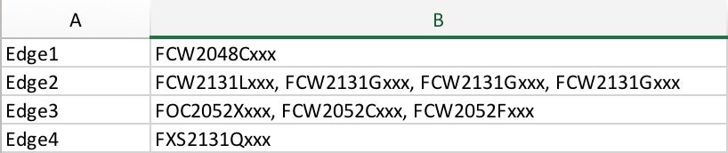
Hostname Map File Format: Catalyst Center expects a CSV file with the hostname and serial number (hostname,serial number) as shown in the following example. For stack LAN automation, the CSV file lets you enter one hostname and multiple serial numbers per row. Use commas to separate serial numbers.
Note
If both device name prefix and hostname map file are used, then the hostname map file takes precedence and the device name prefix will not be used.
Procedure
|
Step 1 |
From the Catalyst Center GUI, click the menu icon and choose . |
||||||
|
Step 2 |
In the Inventory window, choose . |
||||||
|
Step 3 |
Enter the required details and click Start. 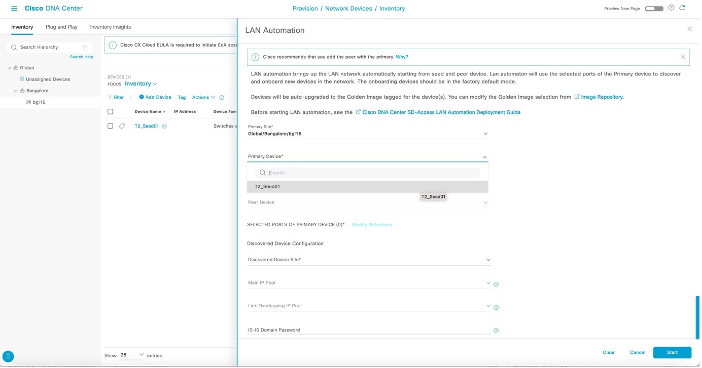
|
||||||
|
Step 4 |
After LAN automation starts, click LAN Automation Status to monitor the progress. 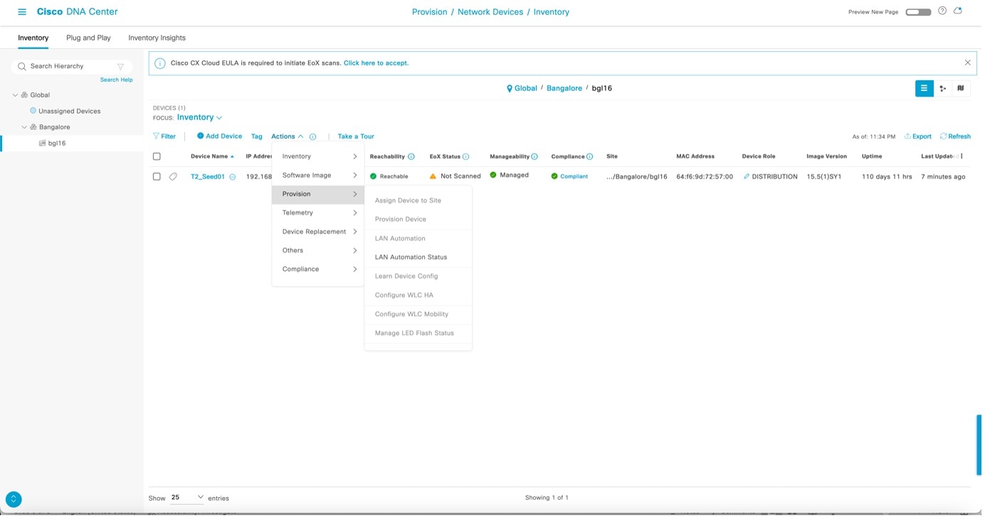
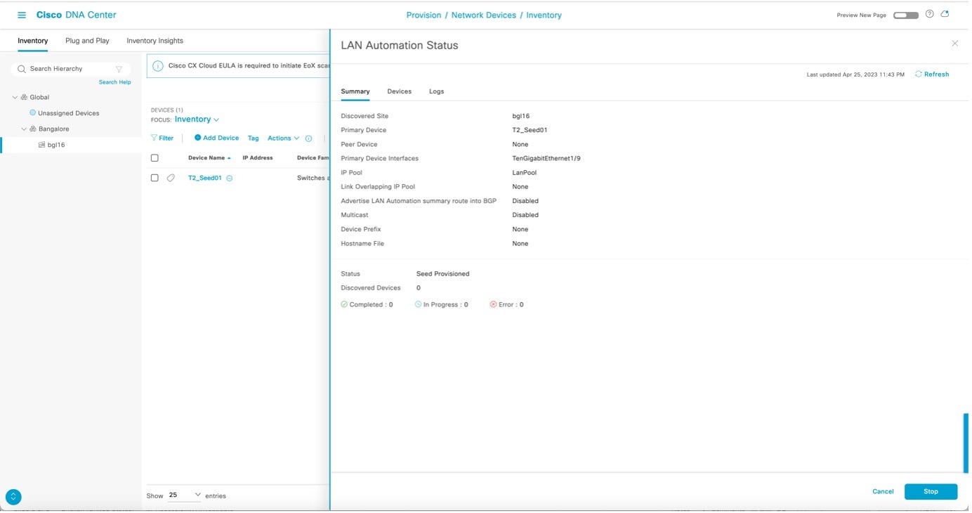
After LAN automation starts, the following sample configuration is pushed to the seed device(s).
|
||||||
|
Step 5 |
After device discovery starts, view logs on the PnP agent.
|
||||||
|
Step 6 |
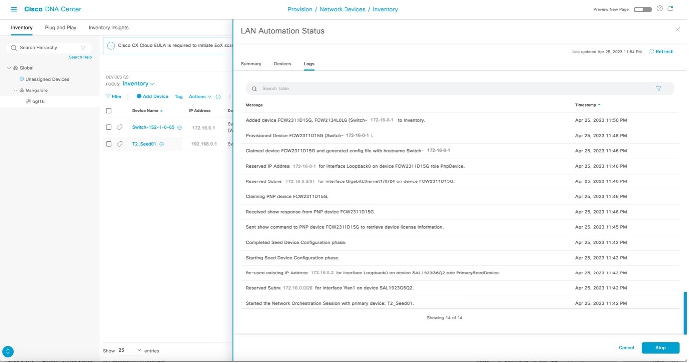
After the device is discovered, Catalyst Center checks if a golden image is marked for the switch family of the discovered device. If a golden image is marked and the discovered device is not running the golden image, LAN automation first upgrades the discovered device to the golden image. If not, Catalyst Center skips the image upgrade and pushes the initial device configuration. The following logs show when the image is upgraded. Catalyst Center pushes part of the configuration, allowing the devices to be onboarded and managed by Catalyst Center. LAN Automation Status displays In Progress, Discovered Devices Status displays the aggregate status of all devices being discovered, and the Devices tab displays the status of individual devices being discovered. 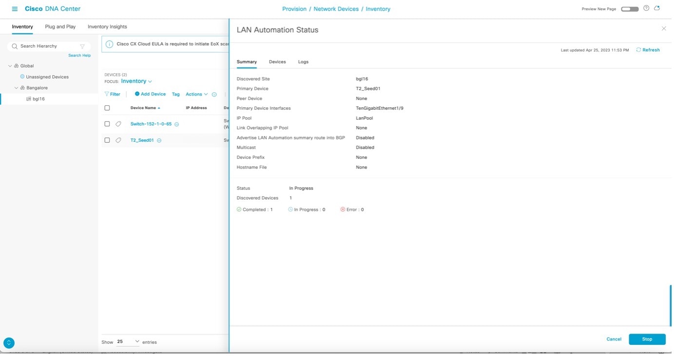
|
||||||
|
Step 7 |
View the logs on the PnP agent, as shown in the following example. It is safe to press return on the console if you want to. When you press return, the hostname changes to the value entered in the Hostname Mapping field when you started LAN automation. After all devices are discovered, the Discovered Devices status changes to Completed and the discovered devices are added to the inventory.
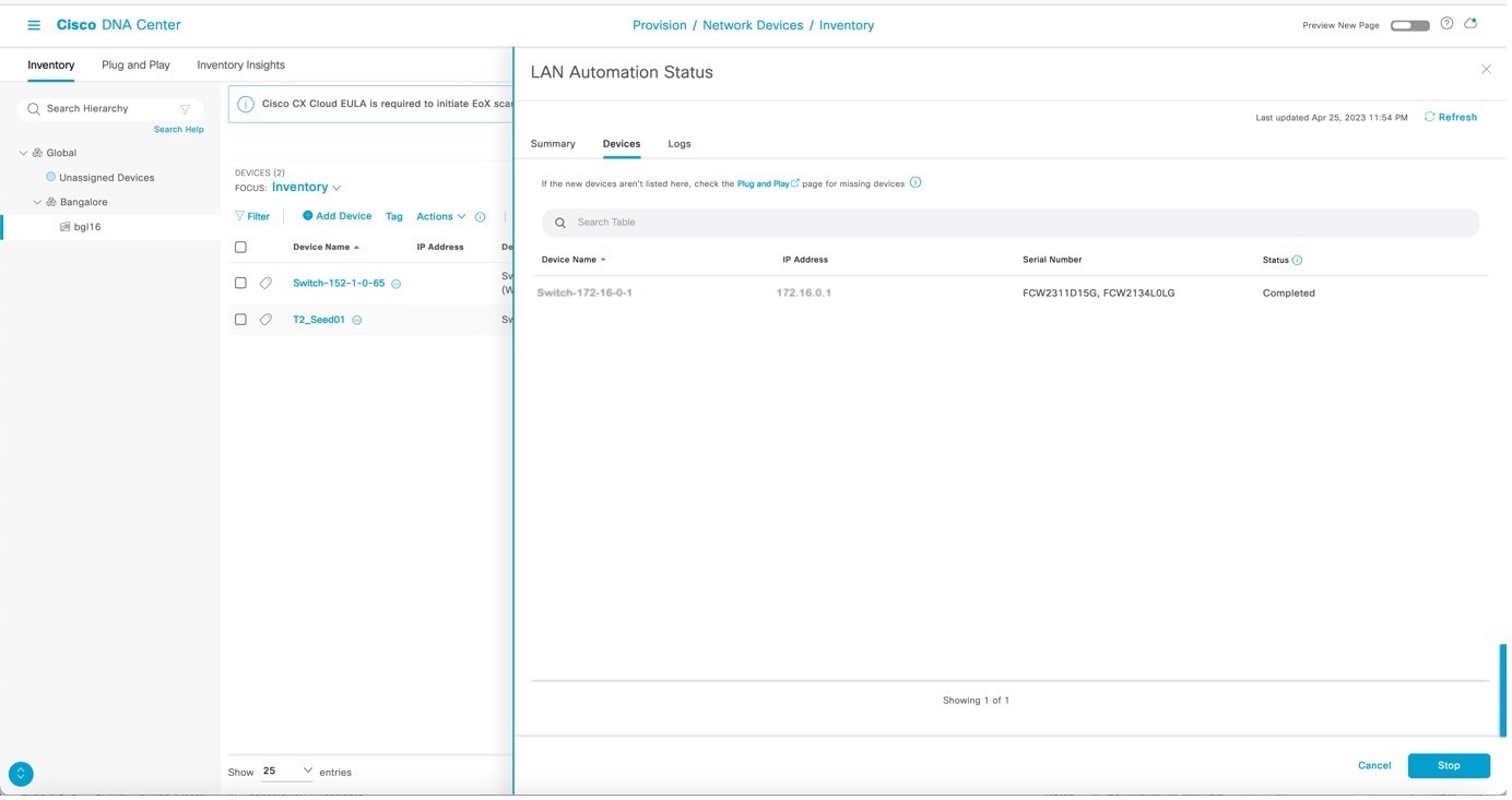
|
||||||
|
Step 8 |
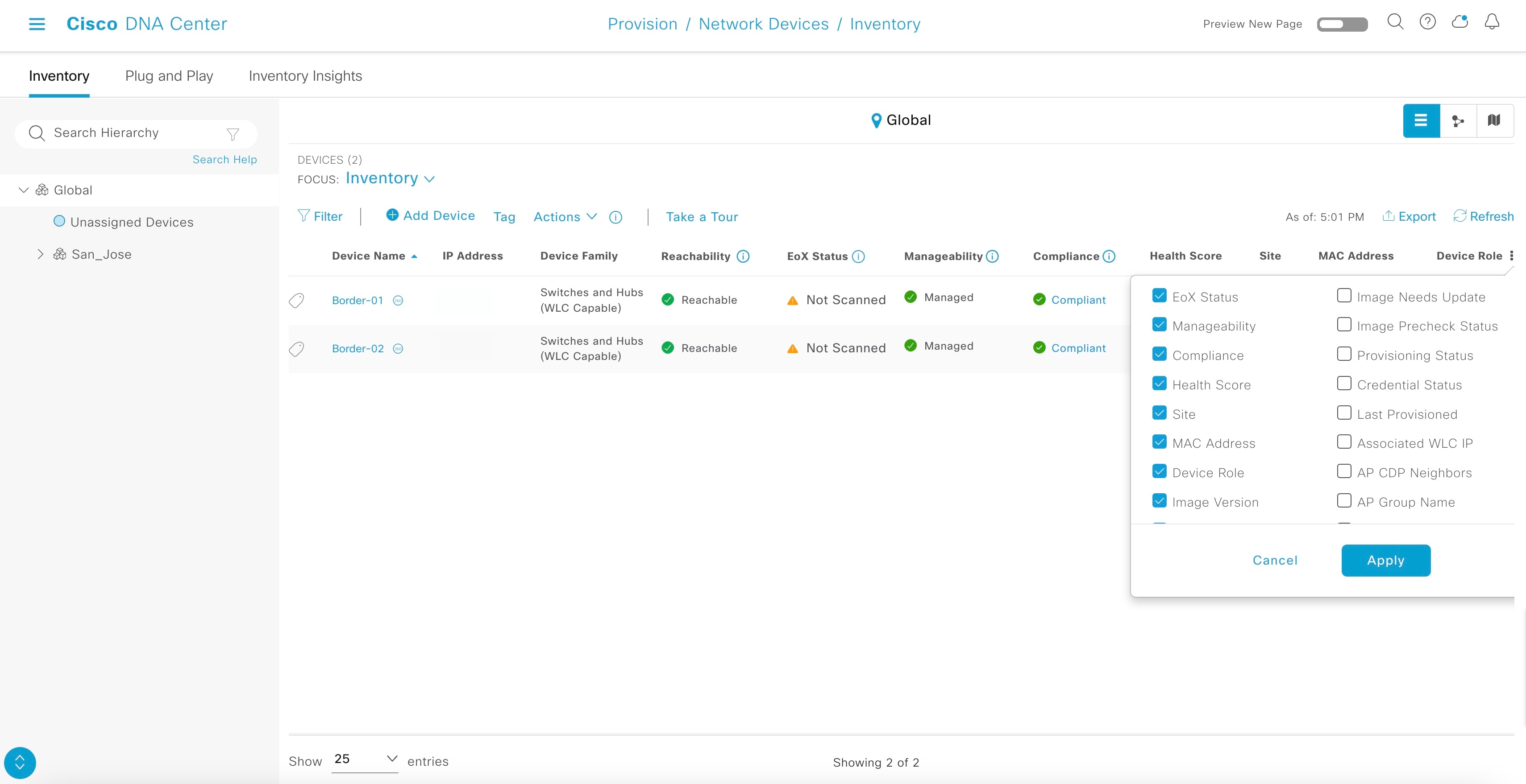
From the Catalyst Center home page, click the menu icon and choose and filter by serial number. The newly discovered switches appear as Managed. The following example shows a sample configuration pushed to discovered devices.
|
||||||
|
Step 9 |
After the Discovered Devices status changes to Completed and all discovered devices are displayed in the inventory as Managed, you can stop LAN automation. However, before stopping LAN automation, check the Topology page to make sure that the links between the discovered device and primary and peer seed are displayed. Choose and click the physical links between the seed and discovered device. Make sure that the interfaces are correct. If the physical links are not visible, resynchronize the seed device where the physical links connect. After resync, check the Topology page again to make sure that the links are visible before stopping LAN automation. |
Stop LAN Automation
You can stop LAN automation to finish discovering all required devices and to prevent inadvertent discovery of additional devices.
In the LAN Automation Status window,click Stop.
After you click Stop:
-
The remainder of the configuration is pushed to network devices, which includes converting the point-to-point links from Layer 2 to Layer 3.
-
The VLAN 1 configuration is removed and the VLAN 1 IP addresses are returned to the LAN automation pool.
-
The device is onboarded in Catalyst Center and assigned to the site.
After the LAN automation stop process is initiated, the LAN Automation Status changes to STOP in Progress.
After LAN automation stops, the following sample configuration is pushed to the discovered device.
The network orchestration service issues a RESYNC for seed and PnP devices to retrieve the state of all links. After the initial RESYNC completes, it pushes the Layer 3 configuration on all Layer 2 links. Finally, it reissues RESYNC to resynchronize the cluster's link state.
The Layer 3 link configuration is pushed when network orchestration stops. (Each interface pair gets its configuration.)
interface GigabitEthernet1/0/13
 description Fabric Physical Link
 no switchport
 dampening
 ip address 192.168.2.97 255.255.255.252
 ip router isis
 logging event link-status
 load-interval 30
 bfd interval 500 min_rx 50 multiplier 3
 no bfd echo
 isis network point-to-point
After all the point-to-point links between the seeds and discovered devices—including links between peer seed and discovered devices—are configured, the devices are added to the site and synced to Catalyst Center.
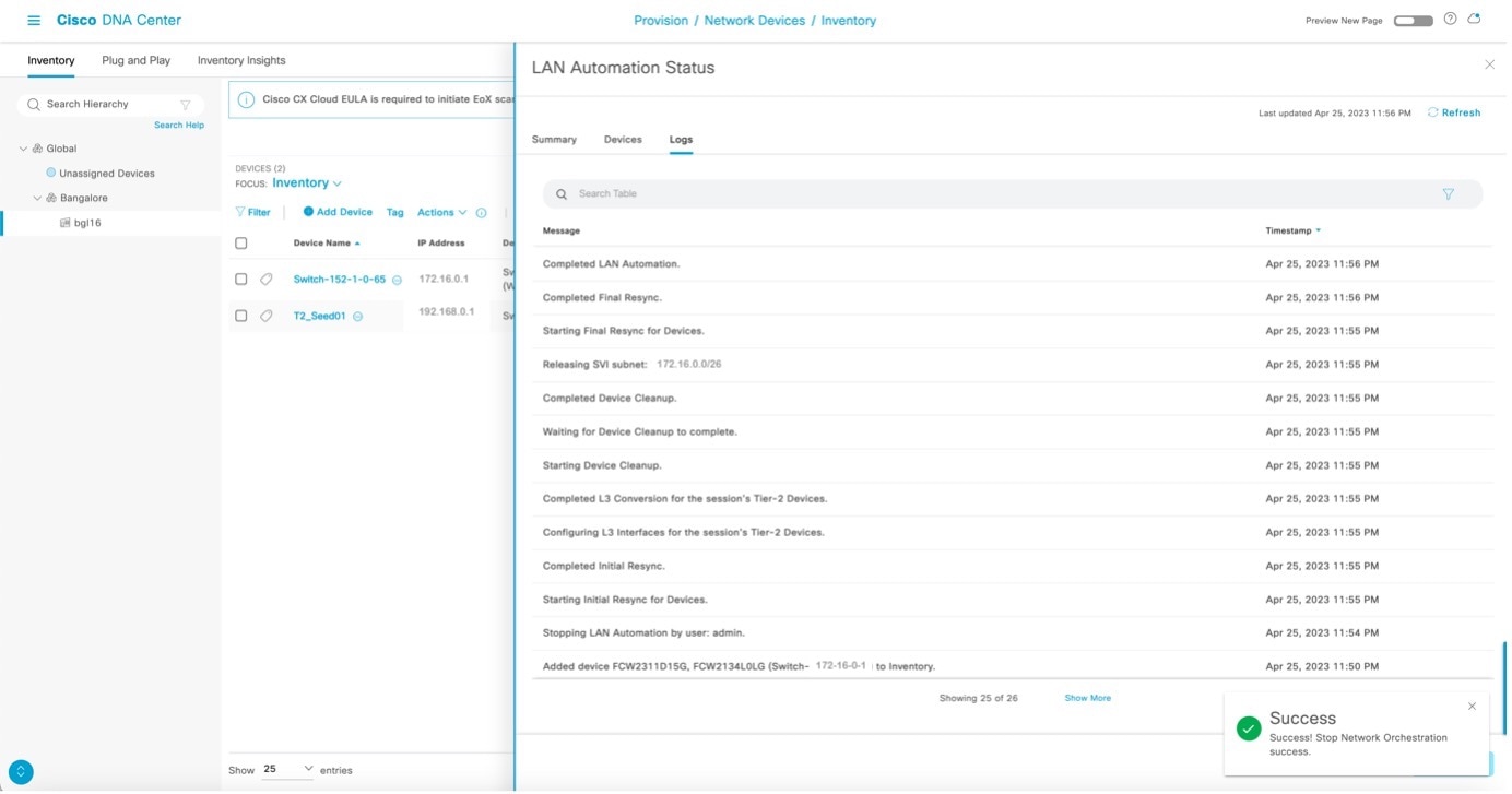
The LAN automation process completes and the LAN Automation Status changes to Completed.
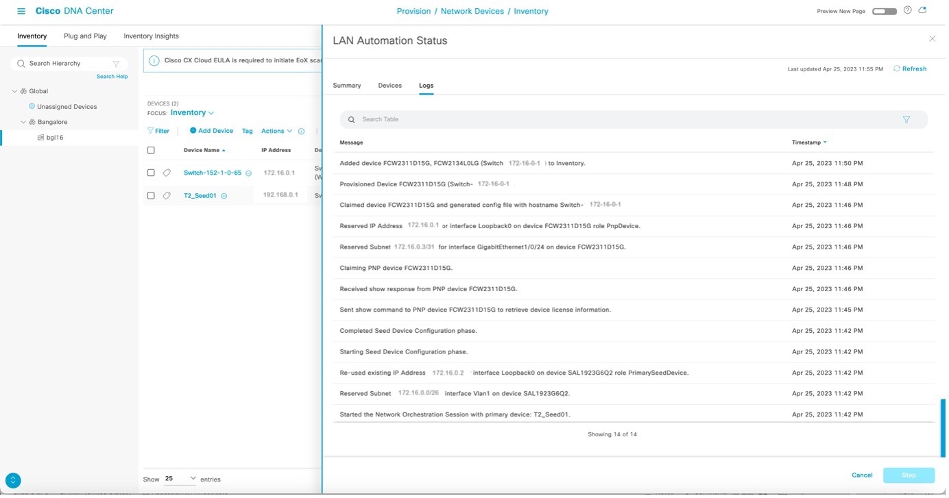
Check the LAN automation logs.
Add Switches and Links to an Existing LAN-Automated Stack
This section describes how to add a new switch, add an existing switch, or configure a link in a LAN-automated stack.
Add a New Switch
This section explains how to add a brand new switch that was never present in Catalyst Center.
You can add switches to a stack that is already LAN automated and in provisioned state without having to LAN automate or discover the new switch.
Procedure
|
Step 1 |
Make sure that the switch was not part of Catalyst Center earlier. (The switch should not be discovered and present in the inventory.) |
||
|
Step 2 |
Make sure that the switch being added has the same image and license version as the provisioned standalone/stack. Use the
commands |
||
|
Step 3 |
Make sure that the switch is in the same boot mode as the stack. It should be in either INSTALL (preferred) or BUNDLE mode. |
||
|
Step 4 |
Use the stack cable to connect the new switch to the stack. Then, power it on. After 2 to 3 minutes, the new switch is added to the stack as a standby (if one switch is already present in the stack) or as a member (if two or more switches are already present in the stack). |
||
|
Step 5 |
Check the output of the commands |
||
|
Step 6 |
After the switch is added to the stack, go to Inventory, select the original provisioned switch/stack, and perform a resync. |
||
|
Step 7 |
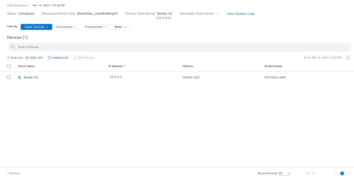
After the sync completes, the new serial number is displayed, completing the addition process.
The following image shows the serial number before the new switch is added. 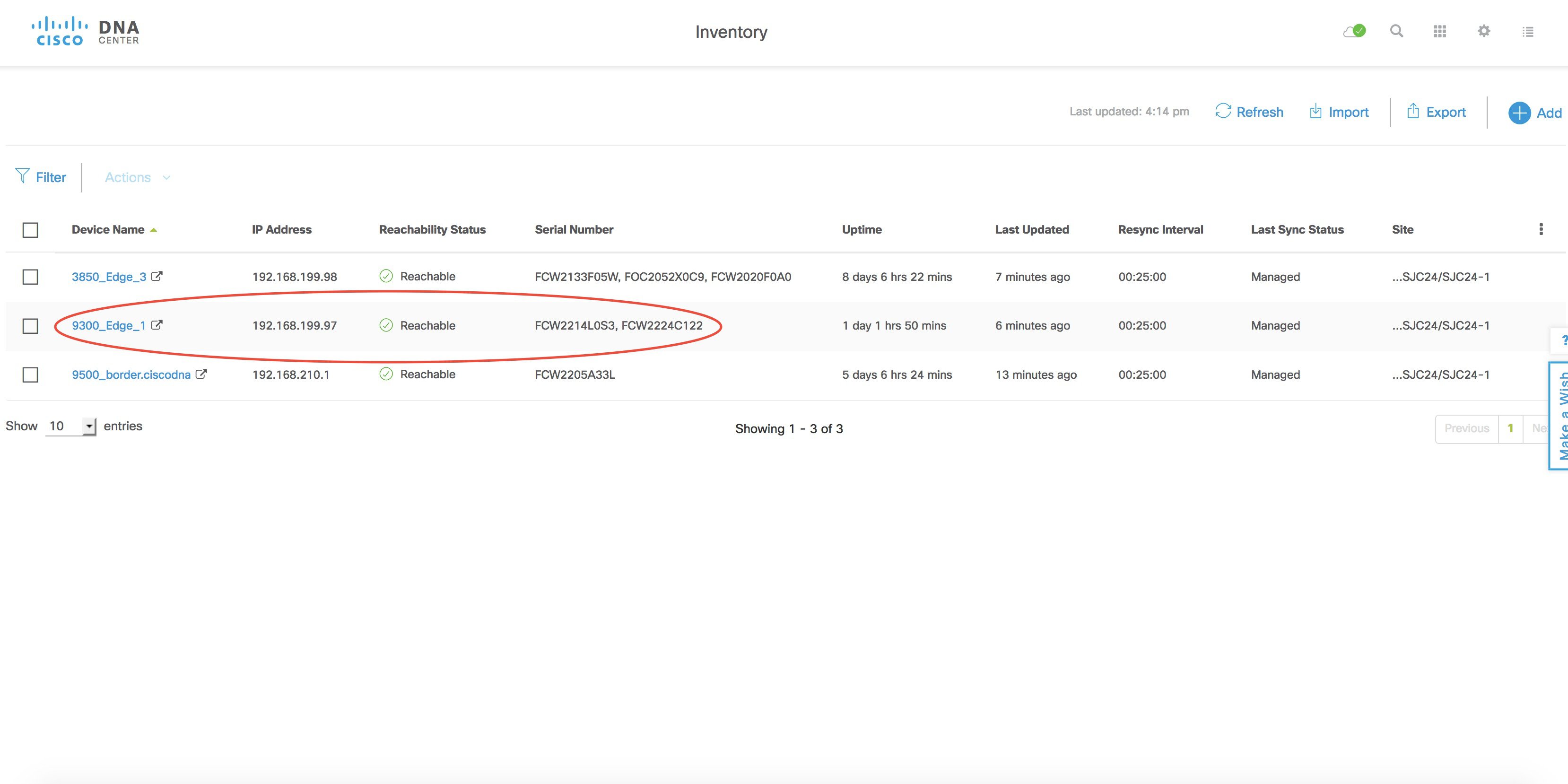 The following image shows the serial number after the new switch is added. 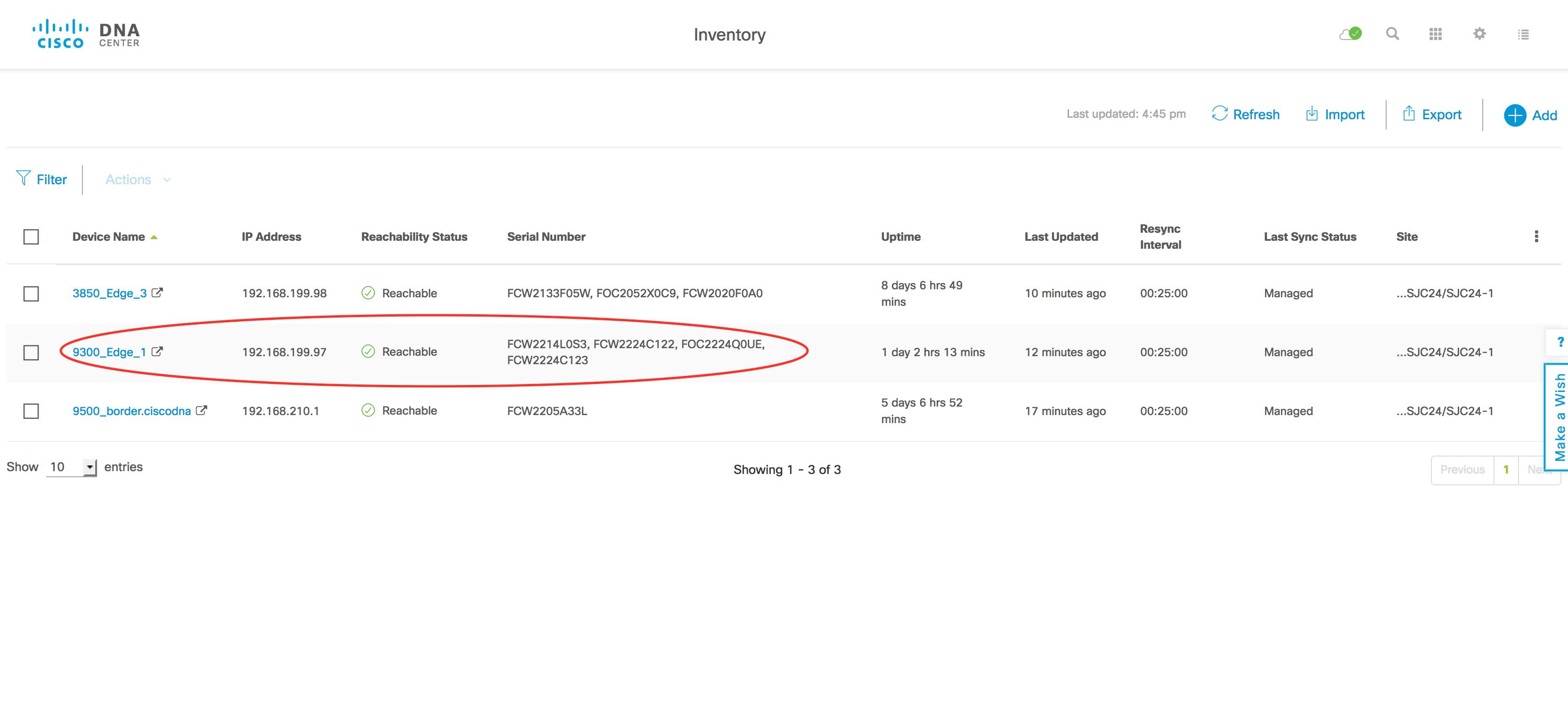 |
Add an Existing Switch
This section explains how to add an existing switch that was already present in Catalyst Center.
If the switch being added was previously LAN automated (part of another stack/standalone) or was discovered by PnP, to add it, you must first remove the switch physically and then remove its entry from the inventory and PnP application/database.
Remove the Switch from Inventory
If the switch is a standalone, from the Catalyst Center home page, click Inventory and select the switch to remove. Choose . If the switch is part of a stack, remove the switch physically, and then resync the original stack. After the sync completes, the removed switch serial number does not appear in the inventory.
Remove the Switch from PnP
-
If the switch is a standalone, first unconfigure
pnp profile pnp-zero-touchfrom the switch and then delete the entry from the PnP database under Device. -
If the switch is part of a stack, remove the switch physically. Make sure that the removed switch does not have
pnp profile pnp-zero-touch; then, delete the entry from the PnP database under Device.
Configure Additional Links After LAN Automation Stops
Use this method when you want to configure:
-
Additional links between the primary and peer seed devices or between distribution devices after LAN automation stops
-
Uplinks from the newly added stack switch to the primary and peer seeds
If you chose the Enable Multicast option the first time LAN automation ran on the device, do not choose Enable Multicast when you configure additional links. Complete the following steps and when LAN automation stops, go to the newly configured Layer 3 ports and manually configure ip pim sparse-mode under the interface.
Procedure
|
Step 1 |
Check the output of the command show cdp neighbors to make sure that the neighbor connected to the new link is displayed. The following sample configuration shows a new link connected to port Ten 4/1/5 on switch 9300_Edge-7. On the other end, the link is connected to switch 9500_border-6 via port For 1/0/1. |
||
|
Step 2 |
Make sure that the ports to which the link is connected (Ten 4/1/5 and For 1/0/1) do not have any Layer 3 configurations on them. If they have Layer 3 configurations, use the default interfaces connected to the new uplink being added and resynchronize both devices. |
||
|
Step 3 |
From the Catalyst Center home page, choose . |
||
|
Step 4 |
In the Primary Device field, enter the switch (for example, 9500_border-6) to which the new link is connected. |
||
|
Step 5 |
In the Peer Device field, enter the switch (for example, 9300_Edge-7) where you want to configure the new link. |
||
|
Step 6 |
Select the port on the primary device where the uplink connects; that is, the port where the PnP device is connected (for example, For 1/0/1). |
||
|
Step 7 |
Use the same LAN automation pool that was used to provision the original stack. |
||
|
Step 8 |
Start LAN automation. Wait for 2 minutes and then stop LAN automation. Because there is no new device discovery to perform, you don't have to go through the entire LAN automation process. After you stop LAN automation, both ports connected to the uplink are configured with an IP address from the same LAN automation pool. |
||
|
Step 9 |
As shown in the following example, after LAN automation stops and completes, both ports are configured for Layer 3 from the LAN pool.
|
Move an Uplink to the Newly Added Switch
You cannot move an uplink from a stack that is already provisioned to a newly added switch in a LAN-automated stack.
Use a 40-G Interface on the Cisco Catalyst 9400
For 16.11.1 and later, Cisco IOS enables the 40-G port on bootup if the following conditions are met:
-
The switch must have its day-0, factory-default configuration. (For information about how to bring a device back to its day-0 configuration, see PnP Agent Initial State.)
-
For a single supervisor, a 10-G/1-G SFP cannot be inserted in any of the SUP ports (ports 1 to 8). A 40-G QSFP must be inserted in ports 9 or 10.
-
For a dual supervisor, a 10-G/1-G SFP cannot be inserted in any of the SUP ports (ports 1 to 8). A 40-G QSFP must be inserted in port 9 only.
Troubleshoot LAN Automation
If you encounter any problems, collect the root cause analysis (RCA) file, which is helpful for troubleshooting. At the CLI, enter:
$ sudo rcaFor a three-node cluster, collect the RCA file for each cluster.
Additional Information: LAN Automation in Catalyst Center Release 2.3.5 and later
The following topic provides information on the LAN automation provisioning based on Catalyst Center Release 2.3.5. The steps and examples may vary for later versions.
For more information on the LAN automation configuration and related features in your Catalyst Center version , see Cisco Catalyst Center User Guide.
Provision LAN Automation
Before you begin
The following topic describes the LAN automation procedure based on Catalyst Center 2.3.5. The steps may vary based on your Catalyst Center version.
Procedure
|
Step 1 |
From the top-left corner, click the menu icon and choose . |
|
Step 2 |
In the LAN Automation window, click Start LAN Automation. 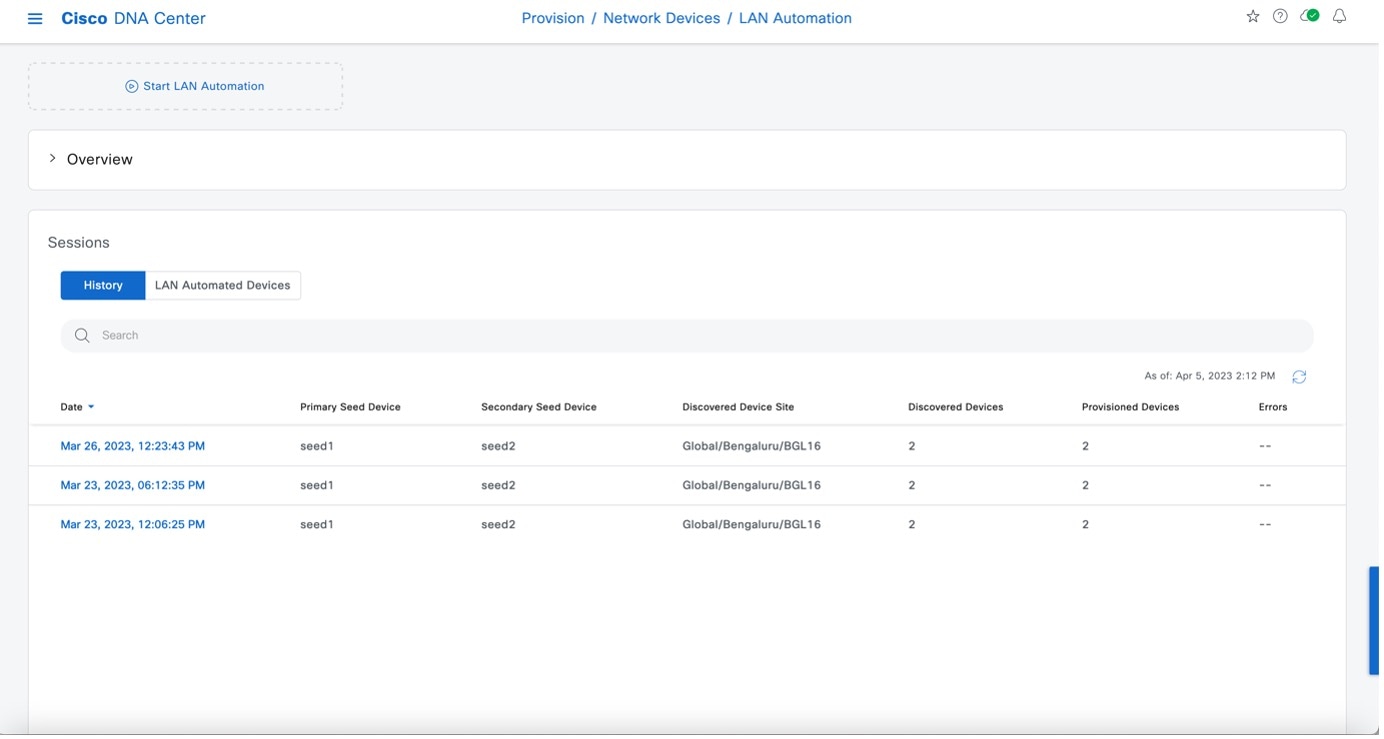
|
|
Step 3 |
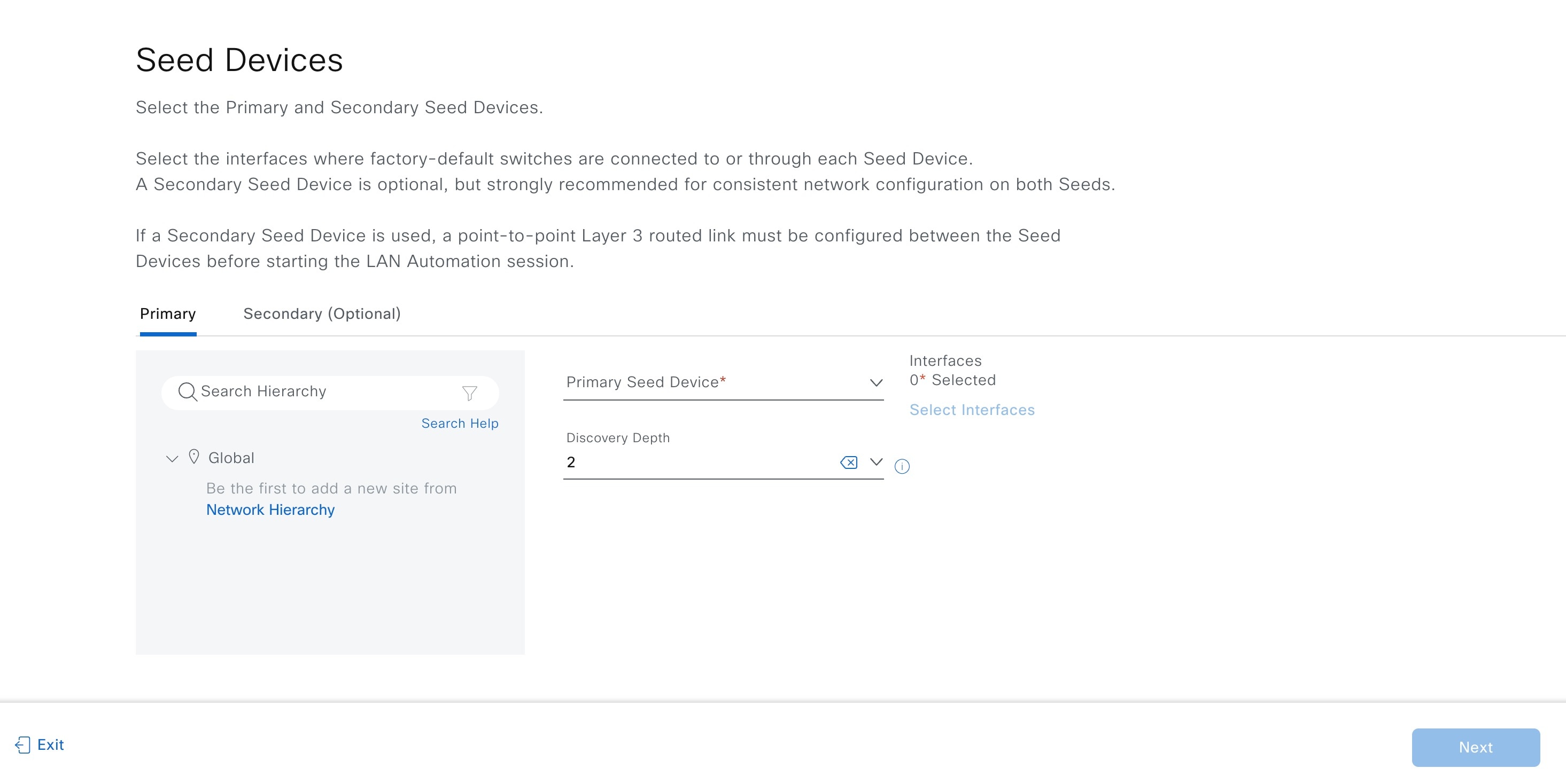
In the Seed Devices window, do the following:
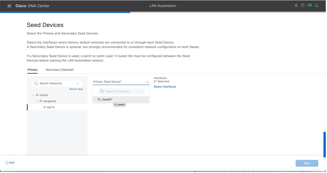
In Catalyst Center Release 2.3.7.5 and later, you can add a discovery depth level for LAN automation. Devices are LAN automated up to the specified level below the primary seed device. The default value is 2. You can review the discovery depth in the summary window and see the specified value in the session details window after the LAN automation starts.
To select the interfaces, in the Select Interfaces window, choose the interfaces and click Add Selected. 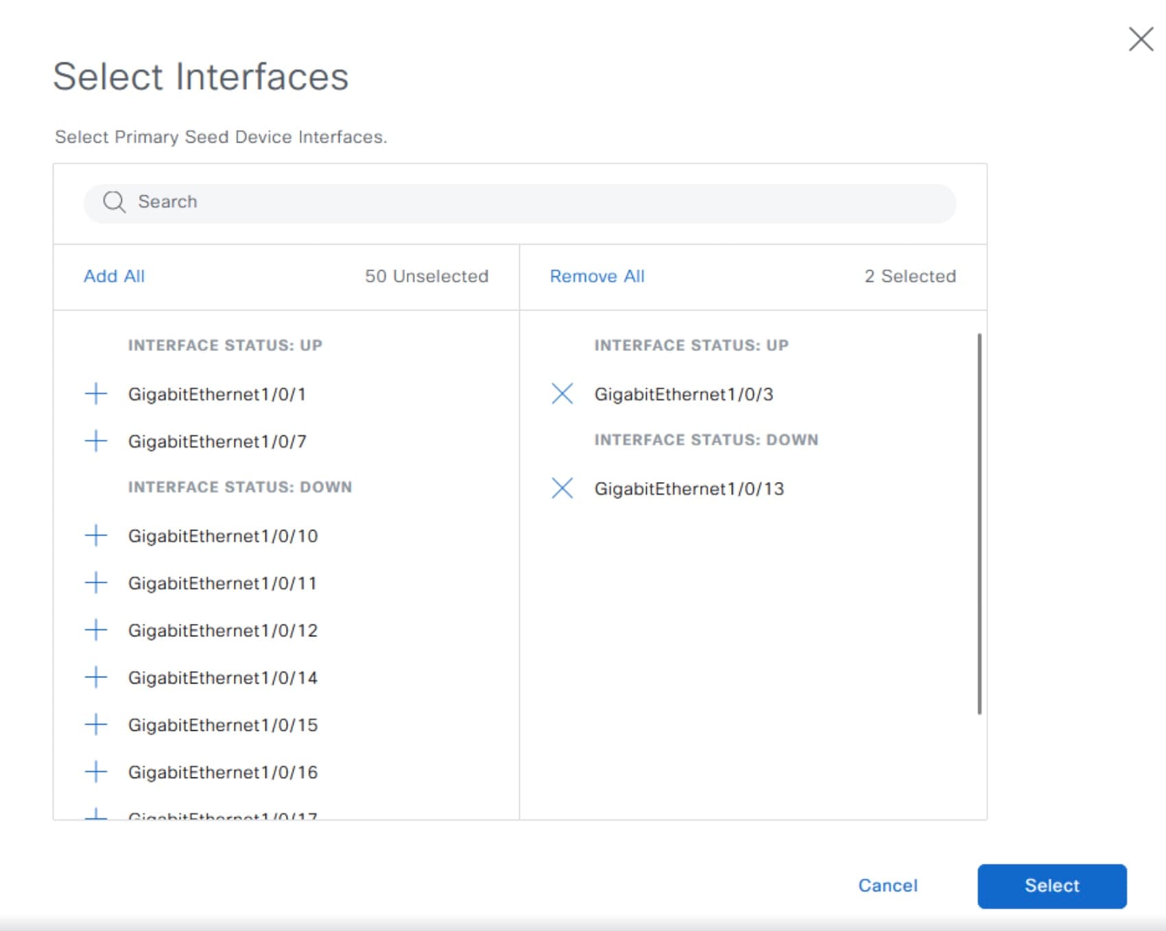
|
|
Step 4 |
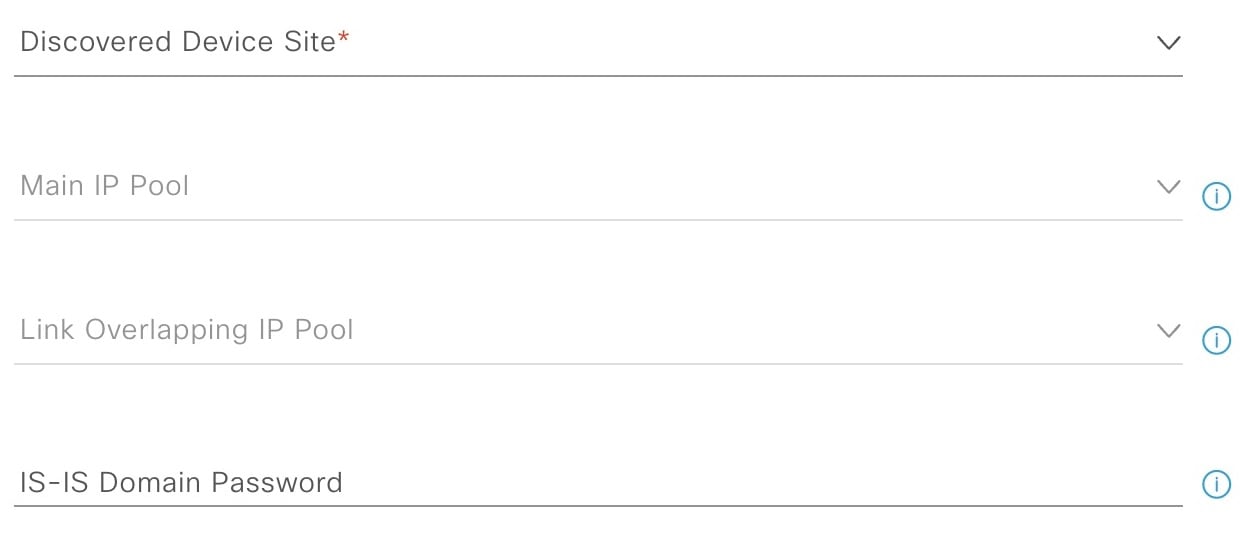
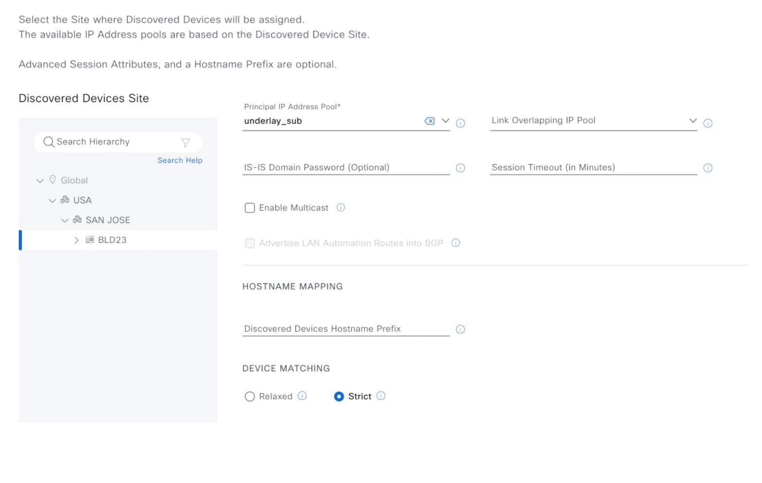
In the Sessions Attributes window, select the Principal IP Address Pool and add the other details as required. 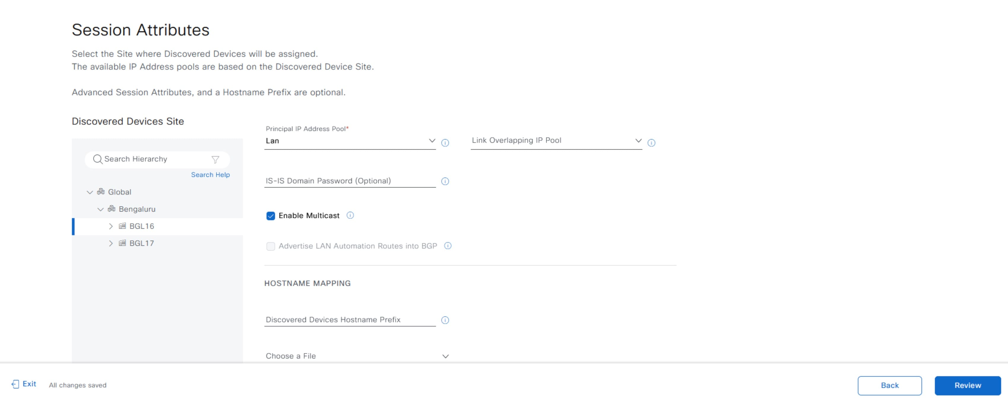
In Catalyst Center Release 2.3.7.5 and later, you can specify the following session attributes.
You can review the session attributes in the summary window and view them in the device details window after the LAN automation is complete. |
|
Step 5 |
Click Review. |
|
Step 6 |
After reviewing the configurations, click Start to start the LAN automation. 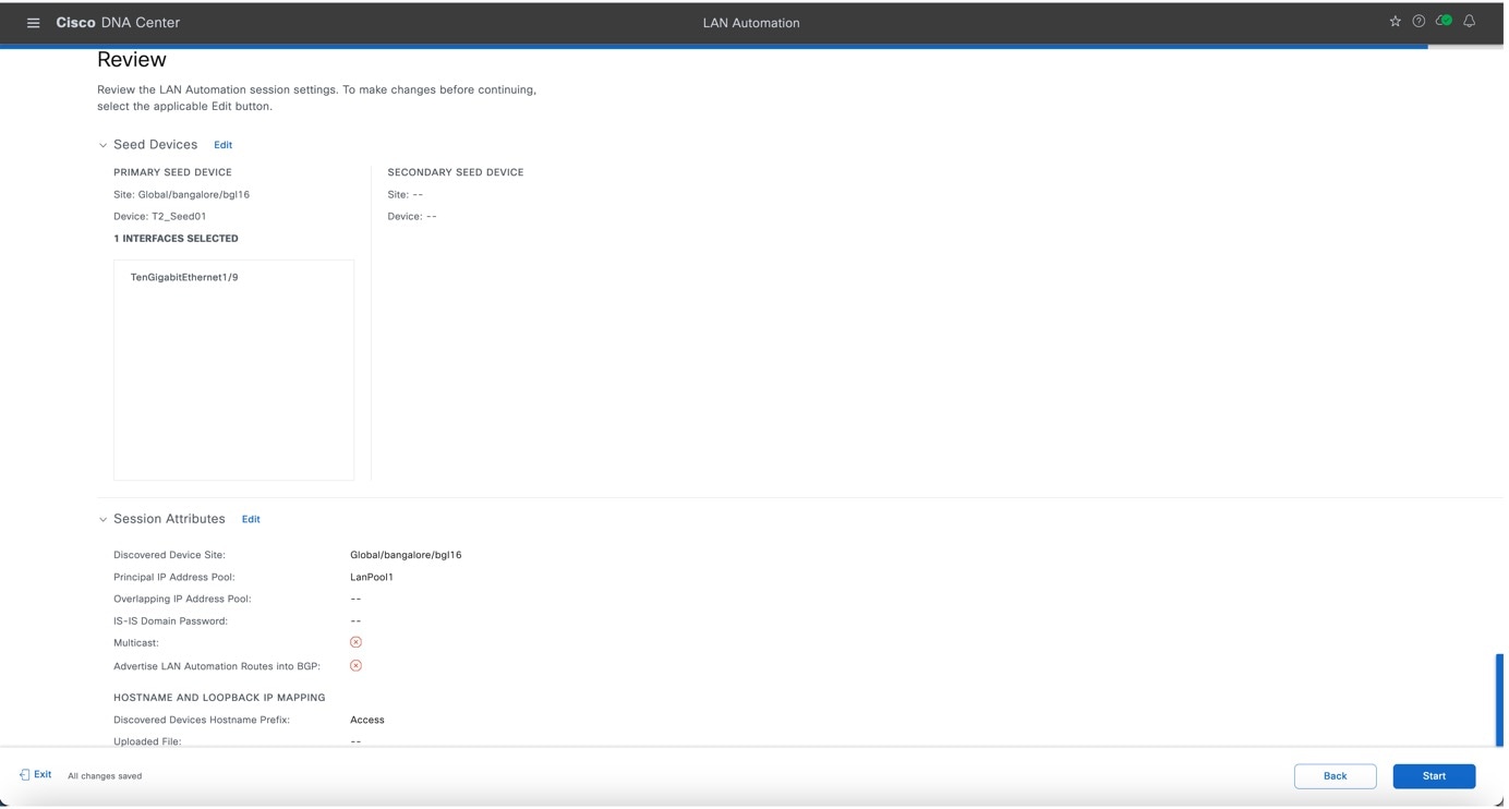
The LAN automation session is created and a tile for the session is displayed in the LAN Automation window. 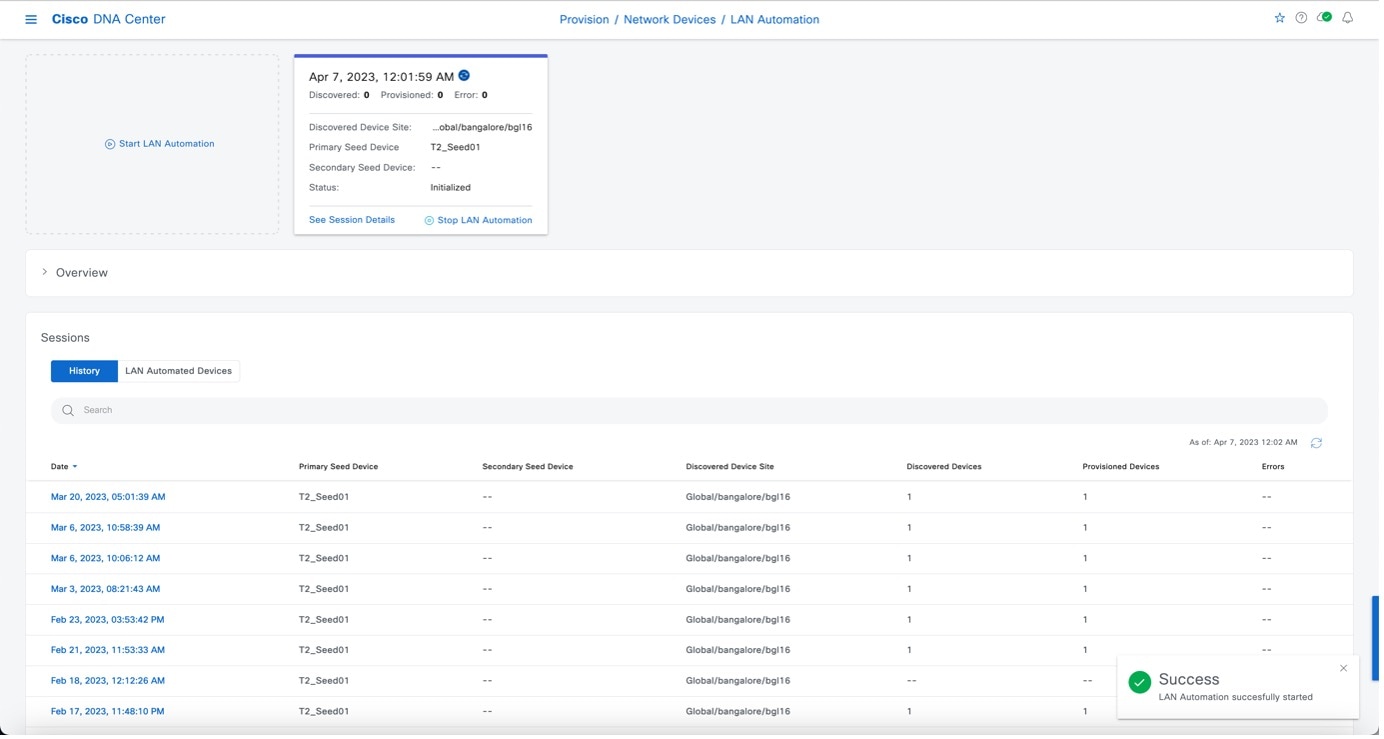
To view the details of the session, click See Session Details in the tile. To view the logs for a session, click View Session Logs in the session details window. The session details window displays the status of the LAN automation session and the devices that are being LAN automated. You can filter the data and see details of the seed devices, discovered devices, provisioned devices, or the error messages. You can stop the LAN automation process when all the devices are provisioned and the progress bar in the Status column shows as complete. 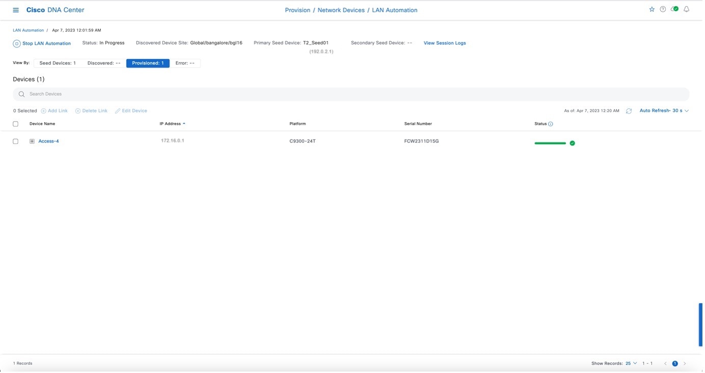
To stop LAN automation for the session, click Stop LAN Automation in the session details window or in the session tile. The LAN automation status changes to STOP in Progress. 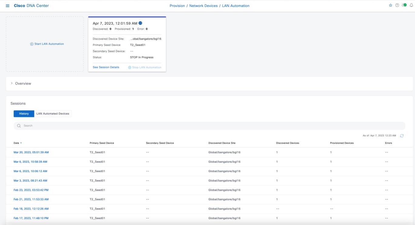
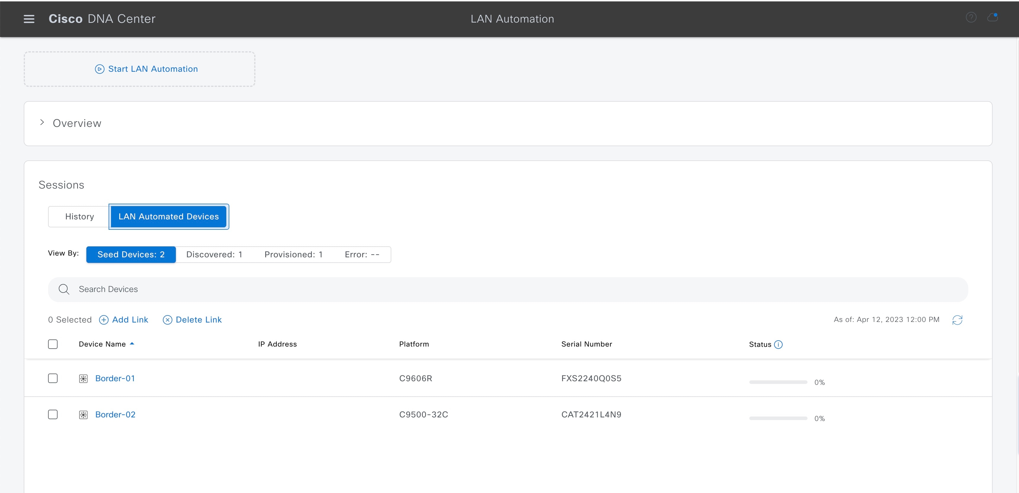
The History tab displays the history of LAN automation sessions in your network. You can use the search field to search for specific text in history. Click the hyperlinked date to view the session details. The LAN Automated Devices tab displays the details of the LAN automated devices. You can use the search field to filter the data based on specific text. Click one of the following toggle buttons to filter the data:
|
Check Device Logs and Configurations
View the LAN automation session logs, device-specific logs, and configurations that are pushed on the device.
Procedure
|
Step 1 |
In the LAN Automation window, click the History tab in the Sessions area and click the hyperlinked date to view the session details. 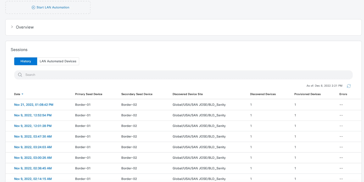
|
|
Step 2 |
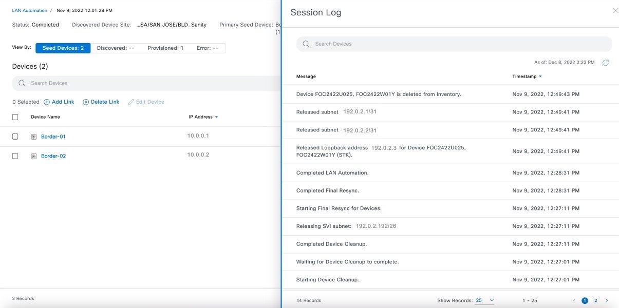
To view the logs for a session, click View Session Logs in the session details window. 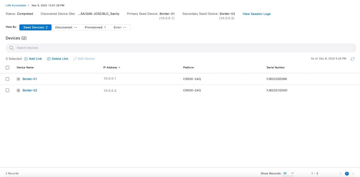
|
|
Step 3 |
To view the device-specific logs and configurations, click on the device name in the session details window. Use the toggle button to filter the devices. The device details are displayed. 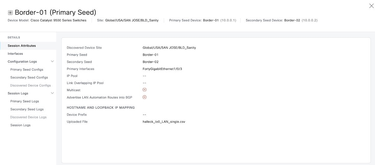
|
|
Step 4 |
To view the configurations that are pushed to the device, expand Configuration Logs in the left pane and select the device configuration. 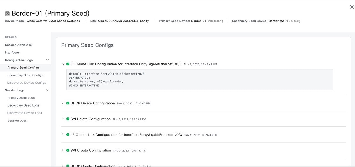
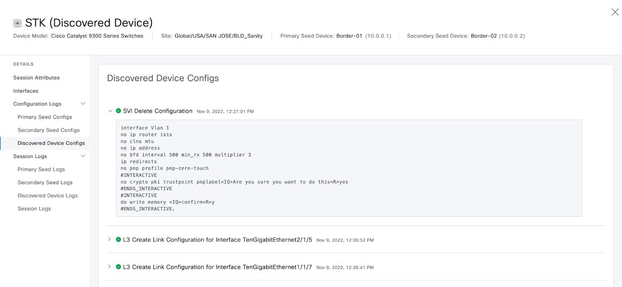
|
|
Step 5 |
To view the device-specific logs, expand Session Logs in the left pane and the select the device log. 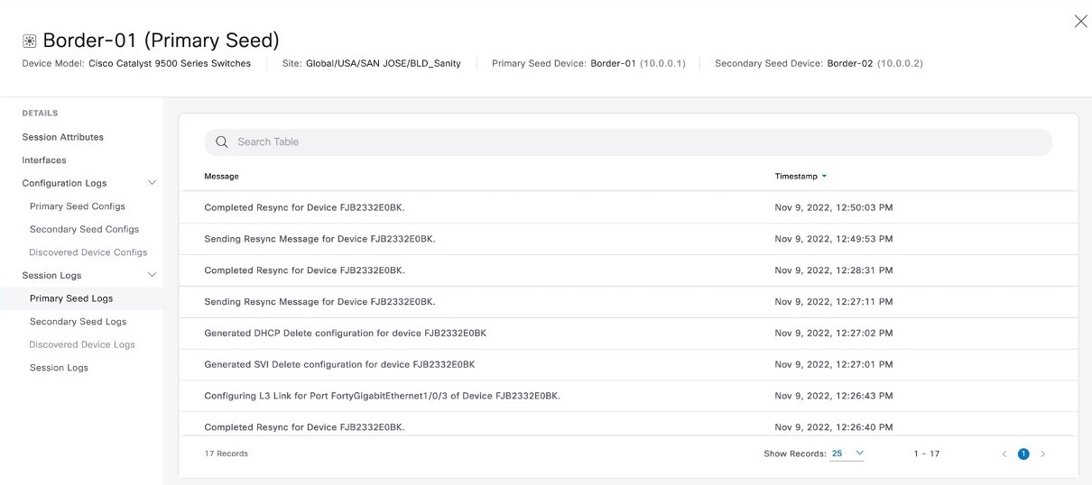
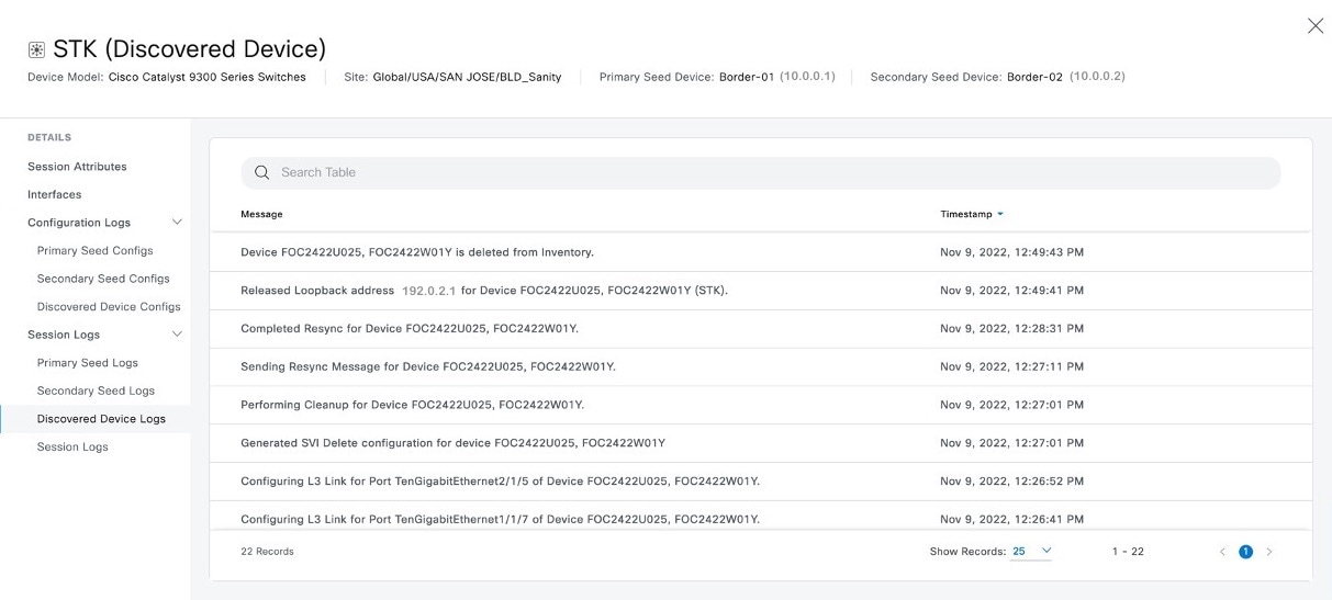
|
Create Link Between Interfaces
Configure additional links between interfaces after LAN automation stops.
Before you begin
The following topic describes the steps to configure additional links between interfaces based on Catalyst Center 2.3.5. The steps may vary based on your Catalyst Center version.
Procedure
|
Step 1 |
From the top-left corner, click the menu icon and choose . |
|
Step 2 |
Use one of the following options:
|
|
Step 3 |
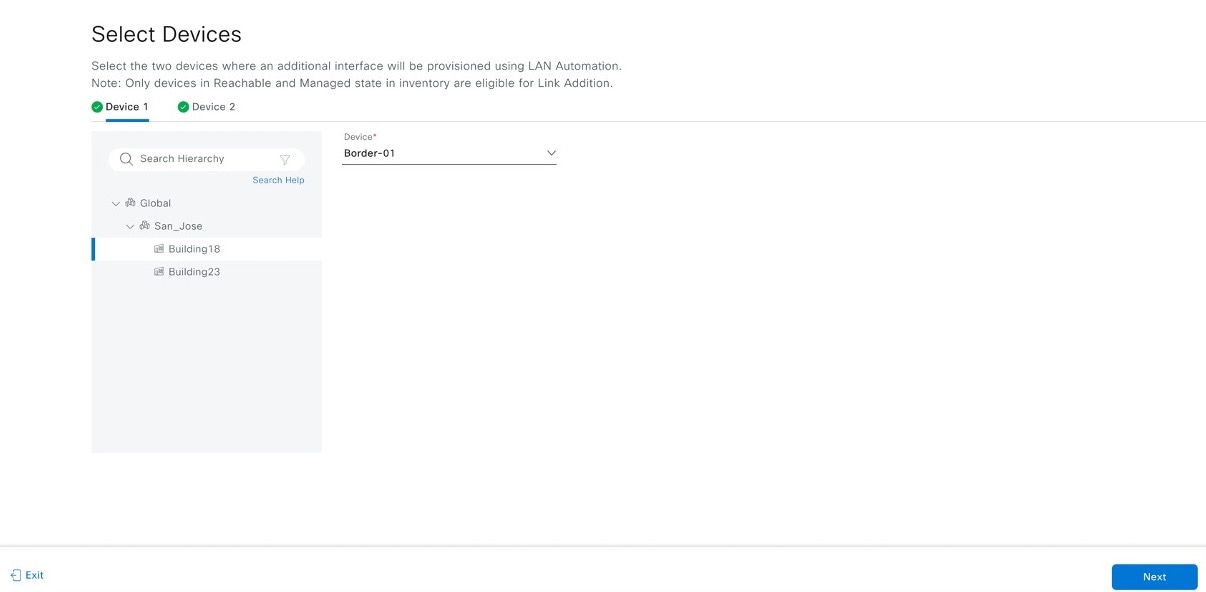
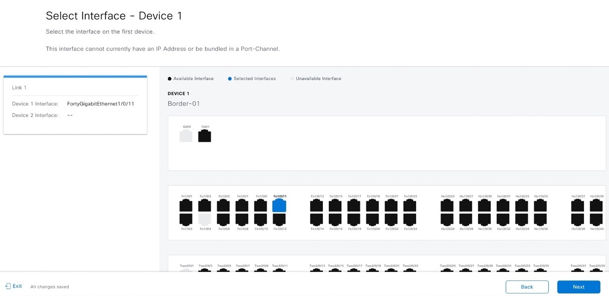
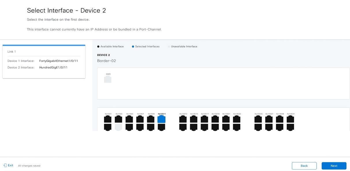
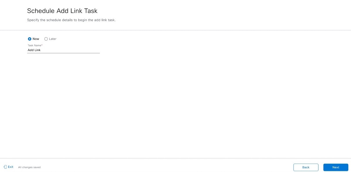
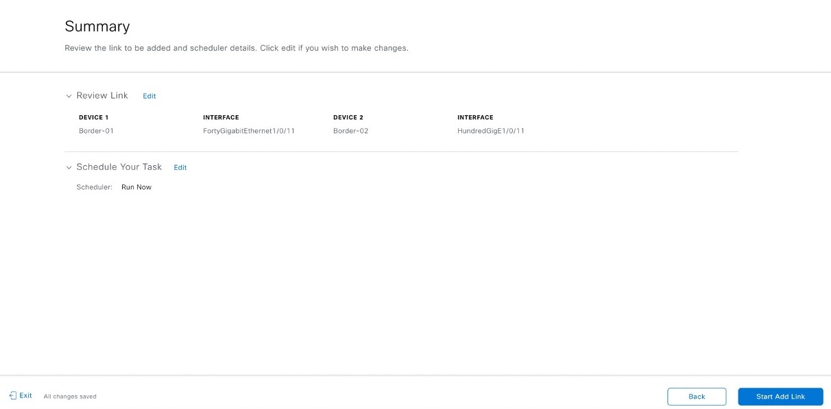
Follow these steps in the Add Link workflow:
|
|
Step 4 |
To see the status of the configuration, click View Status in Activities. |

What to do next
-
Click Delete link.
-
Select the devices and the interfaces.
-
Click Start Delete Link.
Edit LAN Automated Devices
In Catalyst Center Release 2.3.7.5 and later, you can edit the hostname and Loopback0 interface IP address of a LAN automated device.
Before you begin
Ensure that you've reserved LAN IP pools and discovered the devices through LAN automation.
Note |
|
Procedure
|
Step 1 |
From the top-left corner, click the menu icon and choose . |
|
Step 2 |
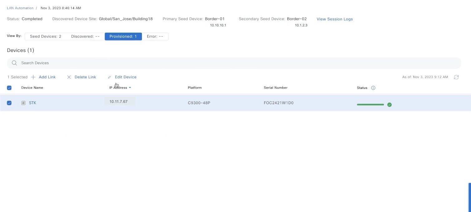
In the LAN Automation window, click the LAN Automated Devices tab. |
|
Step 3 |
Check the check box next to the device that you want to edit and click Edit Device.
|
|
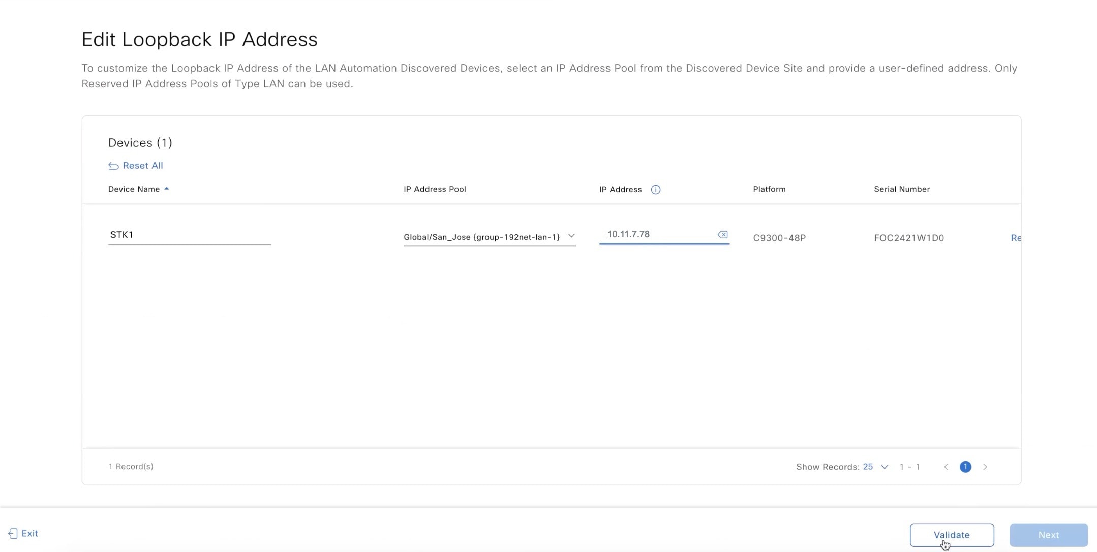
Step 4 |
In the Edit Devices window, edit the Device Name, IP Address Pool, and IP Address fields, as required. Enter the IP address without a subnet mask and ensure that the IP address is within the range of the selected IP address pool.
|
|
Step 5 |
Click Validate to validate the IP address allocation. |
|
Step 6 |
After validation, click Next. |
|
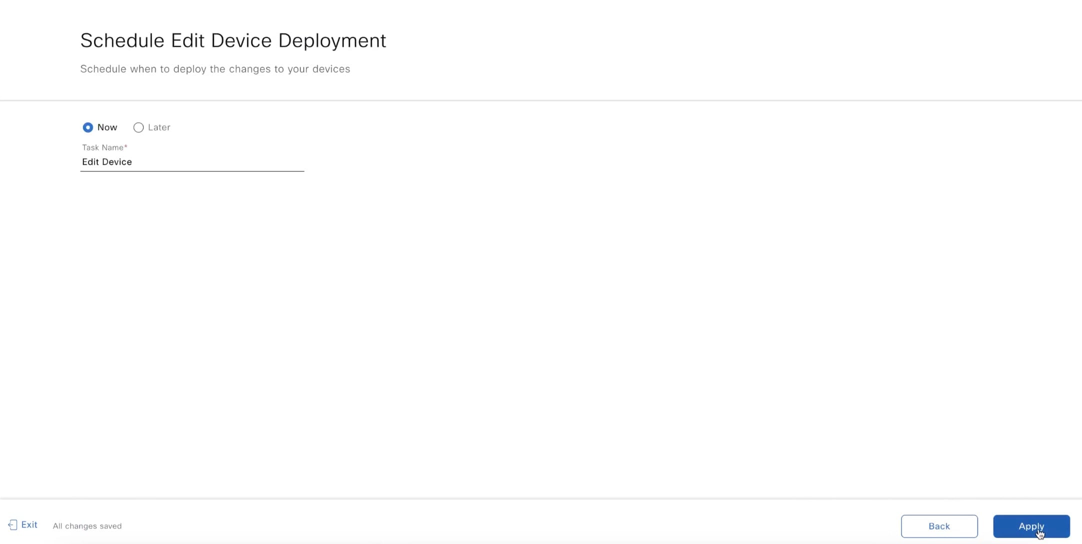
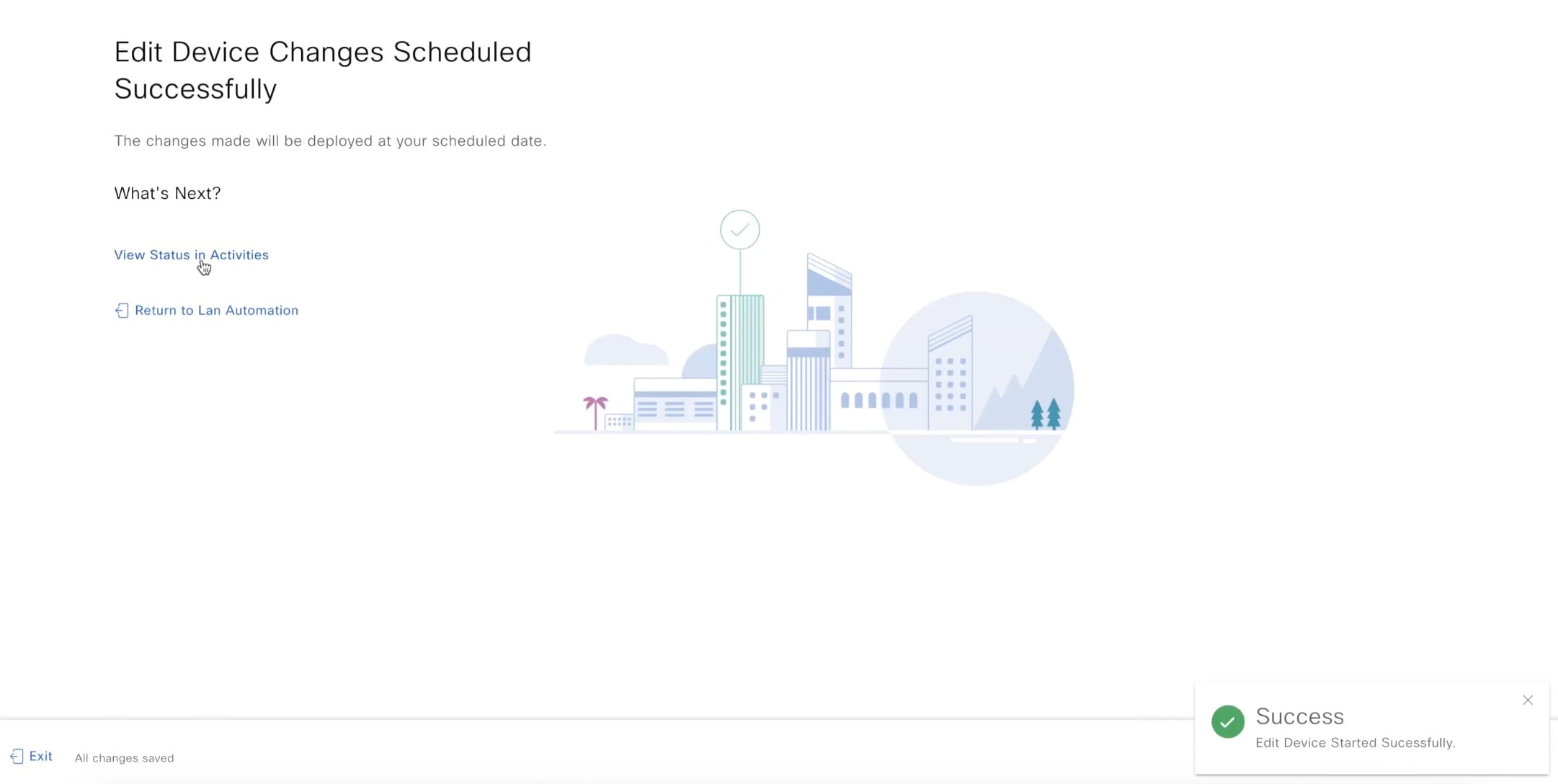
Step 7 |
Choose Now or Later to schedule the edit device deployment and click Apply.
|
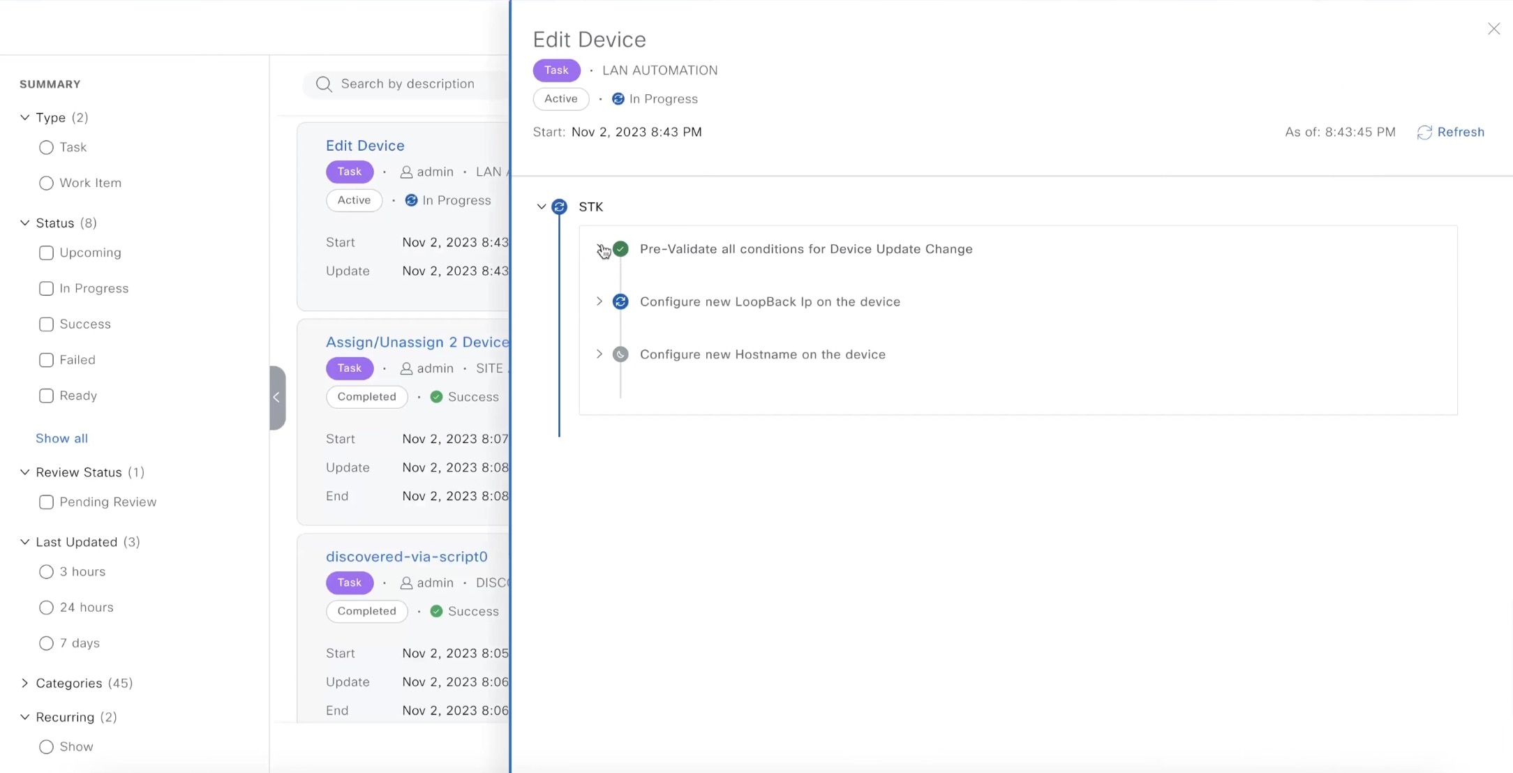
What to do next
You can view the status of the edit task under the window.
Manage Devices in Strict Discovery Mode
In Catalyst Center Release 2.3.7.5 and later, you can choose between the Relaxed or Strict mode for device matching during discovery. In Strict mode, device discovery is restricted to the list of devices provided. Use the following procedure to add, edit, or delete devices from the list.
Procedure
|
Step 1 |
In the LAN Automation window, click Start LAN Automation. |
||
|
Step 2 |
Add the seed devices, and click Next. |
||
|
Step 3 |
In the Session Attributes window, in the left pane, select a building or a floor. |
||
|
Step 4 |
Under Device Matching, select the Strict option. 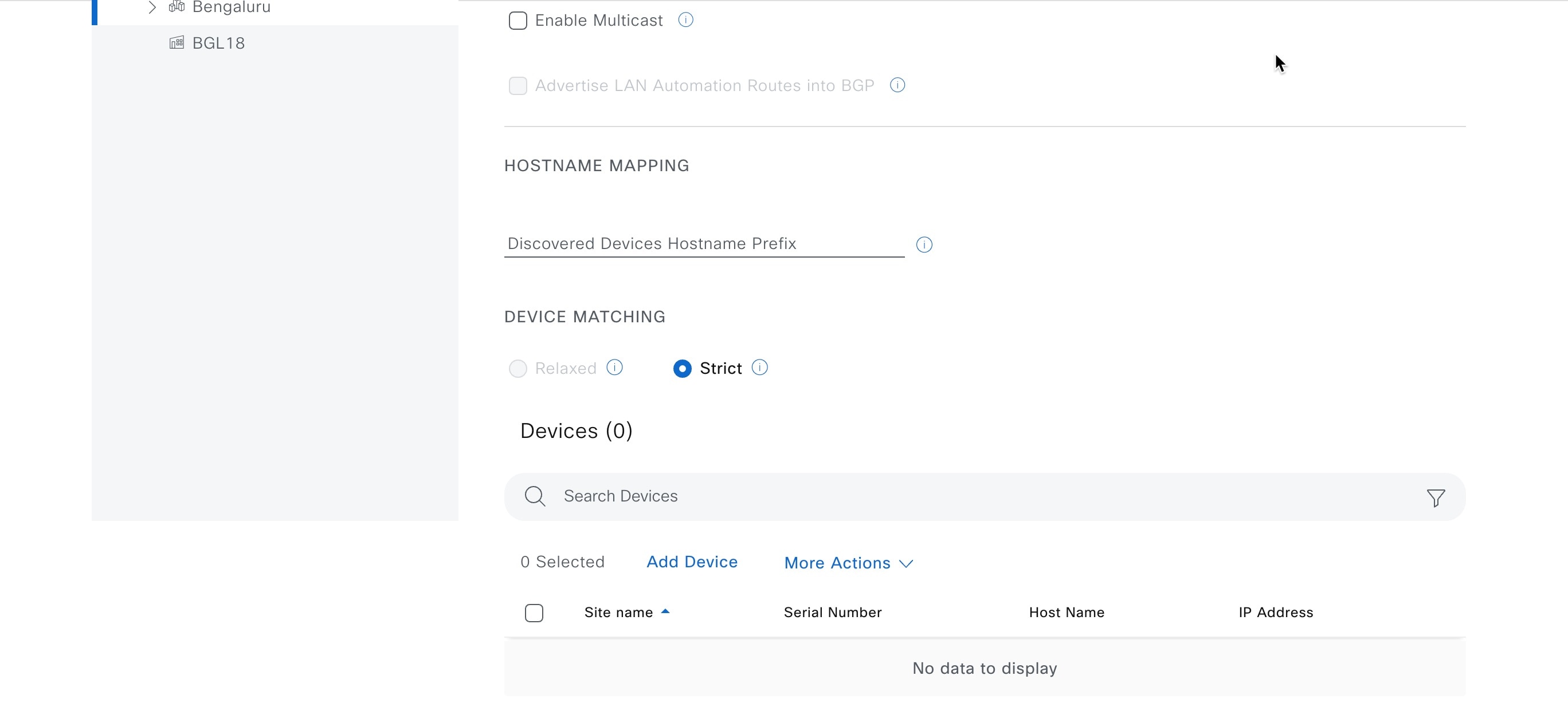
|
||
|
Step 5 |
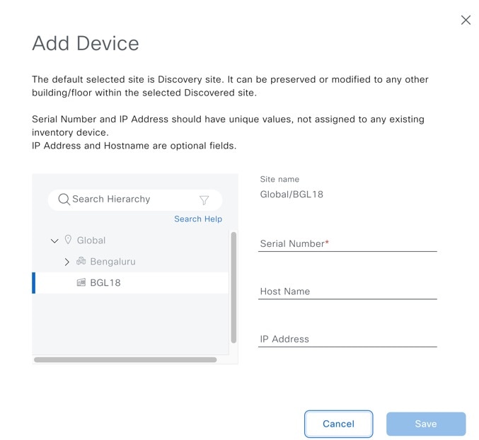
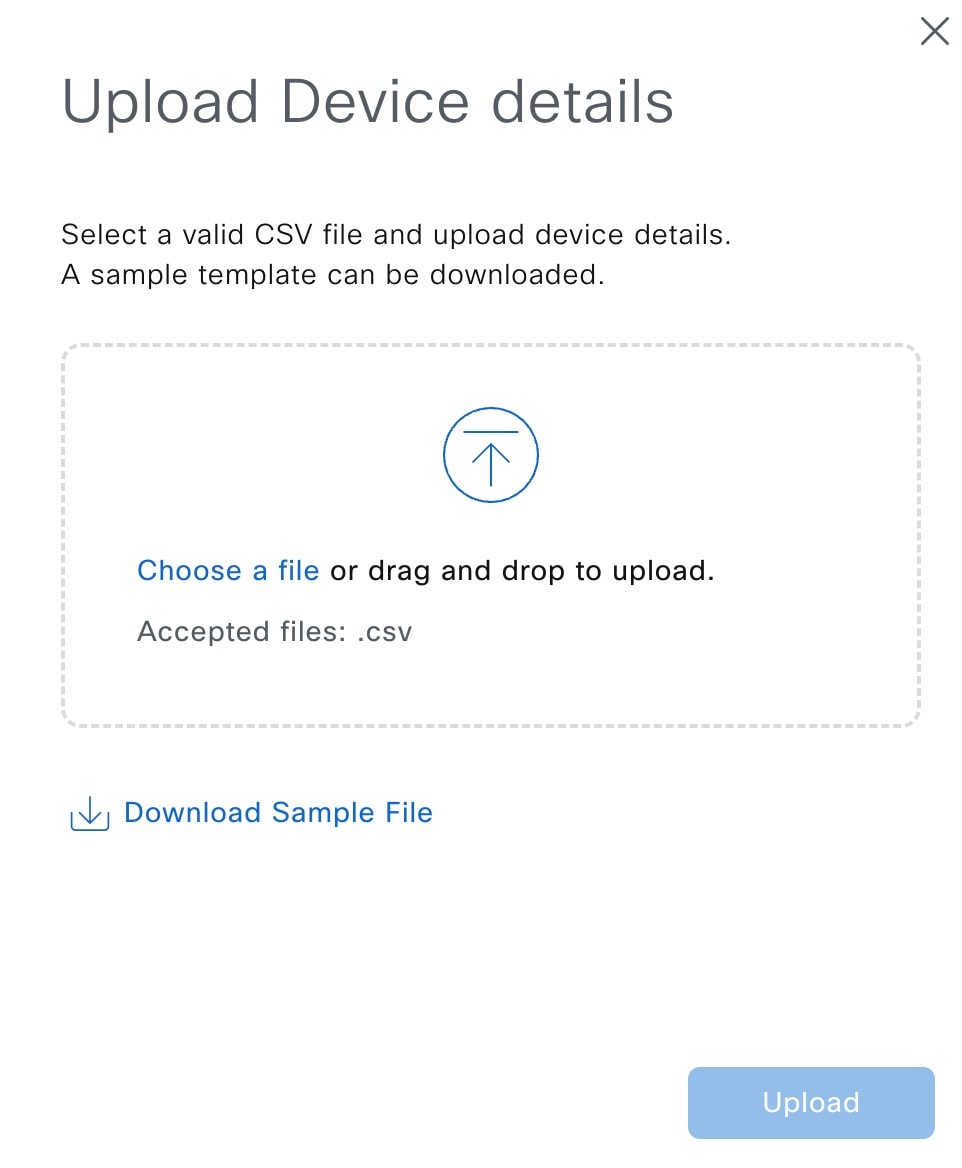
Add devices using one of the following options:
|
||
|
Step 6 |
To edit a device from the list of devices to be discovered, do the following: |
||
|
Step 7 |
To delete a device from the list of devices to be discovered, do the following: |
 Feedback