- Cisco Service Control Mobile Solution Guide
- Table of Contents
- About This Guide
- Introduction to the Cisco Service Control Mobile Solution
- Diameter Interface Support
- Gx Interface Support
- Gy Interface Support
- Gx RLS9 Interface Support
- Capturing and Reporting Subscriber Attributes
- Supported Message Formats
- Supported VSAs
Cisco Service Control Mobile Solution Guide, Release 5.2.x
Bias-Free Language
The documentation set for this product strives to use bias-free language. For the purposes of this documentation set, bias-free is defined as language that does not imply discrimination based on age, disability, gender, racial identity, ethnic identity, sexual orientation, socioeconomic status, and intersectionality. Exceptions may be present in the documentation due to language that is hardcoded in the user interfaces of the product software, language used based on RFP documentation, or language that is used by a referenced third-party product. Learn more about how Cisco is using Inclusive Language.
- Updated:
- September 27, 2015
Chapter: Gx Interface Support
Gx Interface Support
Introduction
The Gx interface may be used for two purposes:
1.![]() Setting the subscriber tunables (for example, package ID) and setting the subscriber RADIUS VSA attributes, which are used by the Gy interface.
Setting the subscriber tunables (for example, package ID) and setting the subscriber RADIUS VSA attributes, which are used by the Gy interface.
The subscriber parameters may be updated either by SCE or by PCRF triggering. SCE-initiated updates are mostly generated by login events, which result in sending CCR Initial/Update messages to the PCRF. PCRF can initiate an update by sending a RAR message to the SCE.
2.![]() New subscriber integration method, where PCRF is responsible for coupling IP to the subscriber name in the SCE.
New subscriber integration method, where PCRF is responsible for coupling IP to the subscriber name in the SCE.
Gx subscriber integration is used by setting Gx as anonymous-group manager (similar to SM pull mode).
Number of Subscriber IP Addresses Supported
The SCE supports a single IP address per subscriber when the Gx interface is used.
Gx Subscriber Properties and AVPs
The PCRF provides the Cisco SCE with the properties related to both Cisco SCA BB, and RADIUS VSA.
The properties that are related to the Cisco SCA BB and are provided by the PCRF to the Cisco SCE are:
These properties are provided in the VSAs described in Table 1-1 .
Vendor-Specific AVPs
Table 1-1 describes the vendor-specific Diameter AVPs defined for the Gx reference point. The Vendor-ID header of all the AVPs defined in this section is set to Cisco.
|
|
Code |
Type |
|
|||||
|
|
|
|
|
|
Not |
Not |
Encr. |
Type |

Note![]() The AVP header bit denoted as “M,” indicates whether support of the AVP is required. The AVP header bit denoted as “V,” indicates whether the optional Vendor-ID field is present in the AVP header. For further details, see RFC 3588.
The AVP header bit denoted as “M,” indicates whether support of the AVP is required. The AVP header bit denoted as “V,” indicates whether the optional Vendor-ID field is present in the AVP header. For further details, see RFC 3588.
- AVP code—1000
- Value type—Uint32
- Used to activate the SCE package as instructed by the PCRF. Defines the policy that will be assigned to the subscriber.
- Can be used either to install or to update the package ID to a subscriber.
Cisco-SCA BB-Real-time-monitor-Install AVP
- AVP code—1001
- Value type—Uint32
- Defines the SCE real-time monitor rule sent by the PCRF to the SCE. Activates and deactivates real-time monitoring for the subscriber.
–![]() Other values fail and are treated as error.
Other values fail and are treated as error.
Cisco-SCA BB-Vlink-Upstream-Install AVP
- AVP—1002
- Value type—Uint32
- Defines the virtual link upstream rule sent by the PCRF to the SCE. Defines the upstream virtual link that the subscriber is assigned to. The virtual link is used to manage a group of subscribers that share a resource.
- Can be used either to install or update the virtual link upstream to a subscriber.
Cisco-SCA BB-Vlink-Downstream-Install AVP
- AVP—1003
- Value type—Uint32
- Defines the virtual link downstream rule sent by the PCRF to the SCE. Defines the downstream virtual link that the subscriber is assigned to.The virtual link is used to manage a group of subscribers sharing a resource.
- Can be used either to install or update virtual link downstream to a subscriber.
Gx Reused AVPs
Table 1-2 lists the Diameter AVPs reused by the Gx reference point from the existing Diameter applications. Other AVPs from the existing Diameter applications, except for the AVPs from the Diameter base protocol, do not need to be supported. The AVPs from the Diameter base protocol are not included in Table 1-2 , but they are reused by the Gx reference point.
Where 3GPP RADIUS VSAs are reused, they are translated to Diameter AVPs, with the exception that the “M” flag is set and the “P” flag may be set.
|
|
|
|
|---|---|---|
Note![]() See Appendix 1, “Supported VSAs” for a complete list of supported VSAs.
See Appendix 1, “Supported VSAs” for a complete list of supported VSAs.
Gx Session
The Gx session is the basic Gx entity and it is uniquely describes a subscriber and single IP mapping. The session is identified by a unique string (called session-id) and it is created both on the server and the SCE. Each Gx message must include the session-id AVP, which identifies the session that the message refers to.
Session Creation
The Gx session creation is initiated by the Cisco SCE. Session creation includes the exchange of Credit Control Request (CCR) and Credit Control Answer (CCA) messages. The Cisco SCE sends a CCR Initial message to the PCRF and the PCRF answers with a CCA message.
In the CCR Initial, the SCE sends the subscriber IP and subscriber name (if no Gx integration is used). The PCRF replies with a CCA Initial message, which includes a subset of the subscriber parameters. After the SCE receives a successful CCA Initial message (including a result AVP with success), the session is successfully opened. If the PCRF CCA Initial message includes error codes, the session is not created, and the Cisco SCE will attempt to reopen it later. However, the subscriber will be assigned to the anonymous group until the Cisco SCE receives a successful CCA initial message. For more details on the error handling of the CCA initial message, see the “Error Handling” section.
Session Lifetime
During the lifetime of a Gx session, the following messages can be sent:
- CCR Update: Similar to CCR Initial, except that the session is already opened. The SCE asks the PCRF for updates on the parameters.
- RAR: Message sent from the PCRF to the SCE to update subscriber parameters. In this case, an external event causes the PCRF to update the subscriber parameters and send the updates to the SCE.
Session End
A session may be ended in either of two ways:
- The SCE may terminate the session by sending a CCR Terminate message. The CCR Terminate message is triggered by logout of the subscriber, either explicit (for example, SM logout) or implicit (by aging).
- PCRF may terminate the session by sending an Abort Session Request (ASR) message. The ASR message is intended to be used in Gx subscriber integration mode where an external event (for example, user disconnecting the mobile modem Internet connection) triggers the PCRF to close the session. The ASR terminates the session in both modes (Gx subscriber integration and other external integration methods). However, in Gx integration, the ASR also triggers a logout of the subscriber from the SCE.
Gx Session Life Cycle
The Gx session life cycle varies based on the whether or not the subscriber integration is external (set as none) or internal. The following sections describe the Gx session life cycles.
Gx Subscriber Integration (None)
In an external subscriber integration method such as SM, the Gx session is created when the subscriber logs in. The subscriber is logged in to the SCE by the external API (for example, SM). When the login process is complete, the SCE tries to open a Gx session for the subscriber and the IP tuple. After the session is created, (the PCRF responded with a successful CCA Initial), the subscriber parameters are extracted from the CCA message and updated. As described earlier, the PCRF may send a RAR message to the SCE during the life time of the session. CCR Updates may be sent to the PCRF as a result of the external API, such as SM sync.
The Gx session is terminated when the external API in use logs the subscriber out. The session can be terminated by sending an ASR message from the PCRF, although this does not trigger subscriber logout.
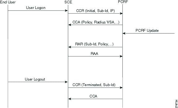
Figure 1-1 shows a typical flow of session messages. The flow starts when a subscriber is logged into the SCE, triggering a CCR and CCA message exchange. The session ends with user explicit logout, which terminates the session.
Figure 1-1 Gx Subscriber Integration (None) Flow
Gx Subscriber Integration
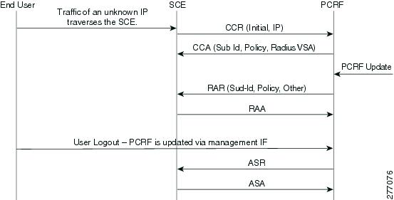
The Gx session life cycle is slightly different when Gx is the subscriber integration method. The Cisco SCE starts the Gx session upon identifying an anonymous IP that belongs to the Gx anonymous-group (similar to SM pull, where a pull notification is created). However, the Cisco SCE does not know the subscriber name, and therefore it is not sent as part of the CCR Initial message. The PCRF responds with a CCA Initial message that includes the subscriber name. The Cisco SCE logs in the subscriber, and sends the IP mapping to the Cisco SCE, together with the subscriber parameters. The Gx session may terminate in two ways, by aging, which generates subscriber logout, or by CCR Terminate, with the PCRF ending the session by sending an ASR. In the second scenario, the ASR also logs out the subscriber from the Cisco SCE because the Gx is the subscriber owner. See Figure 1-2.
Figure 1-2 Gx Anonymous-Group Flow
Whether the session is terminated by aging or by CCR Terminate, the PCRF may send a RAR in order to update the subscriber parameters.
Note![]() Using Gx, the SCE supports single IP mapping per subscriber.
Using Gx, the SCE supports single IP mapping per subscriber.
Configuring Gx Support
This section contains the information and instructions to configure and monitor the Gx support configuration.
Gx Interface CLI Commands
Table 1-3 lists the CLI commands used to configure and monitor the Gx interface.
Example for displaying the Gx configuration:
Example for enabling, disabling, and viewing the Gx pull request status:
Configuring the Maximum Gx Login Rate
Starting from Cisco SCE Release 4.0.0, you can configure the maximum Gx login rate using the diameter Gx login-rate command. This featue is applicable only when subscribers are introduced through Gx.
How to Configure the Maximum Gx Login Rate
From the SCE(config)#> prompt, type:
Configuring the Default Subscription ID Type in Gx
You can configure any of the following subscription ID types as the default subscription ID type by using the party default-type command:
If the default subscription ID type is configured, the Cisco SCE sends the configured subscription ID type to the Policy and Charging Rules Function (PCRF) in the Credit Control Request (CCR) messages. The factory default subscription ID type is END_USER_E164.
How to Configure the Default Subscription ID type
From the SCE(config)#> prompt, type:
|
|
|
|---|---|
Setting the Proxy Bit Flag for Gx and Gy Separately
You can enable peer proxy agent (set the proxy bit flag as true) for Gx and Gy separately using the diameter Gx peer-proxyagent and diameter Gy peer-proxyagent commands respectively.
When the proxy bit flag is set to true, the corresponding proxy bit is enabled on the CCR messages generated by the Cisco SCE and the Credit Control Answer (CCA) messages generated by the PCRF. Further, the proxy bit is enabled on Abort Session Request (ASR) messages, Abort Session Answer (ASA) messages, Reauthorize Request (RAR) messages, and Reauthorization Answer (RAA) messages.
How to Enable Peer Proxy Agent for Gx and Gy
From the SCE(config)#> prompt, type:
|
|
|
|---|---|
High Availability for the Gx Interface
Two parameters define the High Availability (HA) behavior:
- Session shared—Defines whether the session needs to reopen upon failover. When a shared session is defined, it is assumed that each session is common to all the servers (for example, through a common database).
- Stickiness—Defines whether the session needs to move back to the original server when it restarts.
A server is in failure mode if the underlying diameter connection fails and cannot recover for the configurable grace time. Fatal mode is when all the servers are in failure mode and no connections to PCRF exist.
Session not Shared with Stickiness
When the primary server fails, all the sessions managed by that server are migrated to the next server in a controlled manner (limited by the maximum rate allowed).
If the Gx session manages the subscriber, the subscriber is logged out. On the next traffic generating event, the subscriber logs in on a different server. If any other method manages the subscriber, only the Gx session is closed and the session reopens on the secondary server.
Eventually, all the subscribers relog and migrate to the secondary server. After the primary server is up, new sessions are forwarded to it. The migrated sessions on the secondary server continue on the secondary server until logout or failure.
In this scheme, a server failure causes a long convergence time.
In fatal mode, all the Gx-managed subscribers are logged out and all the other subscribers remain with their last configuration. When the connection resumes, the SCE reopens all the non-Gx-managed sessions and the Gx-managed sessions are triggered by traffic.
Servers A, B, and C with priority 100, 99, and 98, respectively.
1.![]() After ten Gx sessions, all the servers are up and all the sessions are opened on server A. Servers B and C do not handle any sessions.
After ten Gx sessions, all the servers are up and all the sessions are opened on server A. Servers B and C do not handle any sessions.
2.![]() Servers A and B fail. The ten sessions are closed and are reopened on server C.
Servers A and B fail. The ten sessions are closed and are reopened on server C.
3.![]() Server B is up. Server C continues to handle all its sessions, new sessions open on server B.
Server B is up. Server C continues to handle all its sessions, new sessions open on server B.
4.![]() After nine more new Gx sessions, server A comes back up. Server A handles no sessions, server B handles nine sessions, and server C handles ten sessions.
After nine more new Gx sessions, server A comes back up. Server A handles no sessions, server B handles nine sessions, and server C handles ten sessions.
Session Shared with Stickiness
In this scheme, the servers share the session. When the primary server is down, all the existing sessions are handled by the secondary server. No relogin is required.
When the primary server is up again, all the new sessions are handled by it, while old sessions that were moved to the secondary server remain on the secondary server until logout.
Fatal mode works in the same way as in a session not shared with stickiness.
Servers A, B, and C with priority 100, 99, and 98, respectively.
1.![]() After 10 Gx sessions, all the servers are up and all the sessions are opened on server A. Servers B and C do not handle any sessions.
After 10 Gx sessions, all the servers are up and all the sessions are opened on server A. Servers B and C do not handle any sessions.
2.![]() Servers A and B fail. The 10 sessions are handled by server C without being closed (no action is taken). When a message needs to be sent, it is sent to server C, and remains with server C until the session is closed.
Servers A and B fail. The 10 sessions are handled by server C without being closed (no action is taken). When a message needs to be sent, it is sent to server C, and remains with server C until the session is closed.
3.![]() Server B is up. Again no action is taken, all the messages related to the new sessions are sent to server B. Any messages related to the sessions handled by server C (Step 2) remain with server C.
Server B is up. Again no action is taken, all the messages related to the new sessions are sent to server B. Any messages related to the sessions handled by server C (Step 2) remain with server C.
4.![]() After nine more new Gx sessions, server A comes back up. If a message was generated in Step 2 or 3 for a session, it remains with server B or server C, respectively. All the other messages are sent to server A.
After nine more new Gx sessions, server A comes back up. If a message was generated in Step 2 or 3 for a session, it remains with server B or server C, respectively. All the other messages are sent to server A.
Session Shared Without Stickiness
Same as the session shared with stickiness with the exception that when the primary server recovers, all the sessions are re-forwarded to it.
Fatal mode works in the same way as in a session shared with stickiness.
Servers A, B, and C with priority 100, 99, and 98, respectively.
1.![]() After 10 Gx sessions, all servers are up, and all the sessions are opened on server A. Servers B and C do not handle any sessions.
After 10 Gx sessions, all servers are up, and all the sessions are opened on server A. Servers B and C do not handle any sessions.
2.![]() Servers A and B fail. The 10 sessions are handled by server C without being closed (no action is taken). When a message needs to be sent, it is sent to server C.
Servers A and B fail. The 10 sessions are handled by server C without being closed (no action is taken). When a message needs to be sent, it is sent to server C.
3.![]() Server B is up. No action is taken, all the messages are sent to server B.
Server B is up. No action is taken, all the messages are sent to server B.
4.![]() After nine more new Gx sessions, server A comes back up. No action is taken, all the messages are forwarded to server A.
After nine more new Gx sessions, server A comes back up. No action is taken, all the messages are forwarded to server A.
Load Balancing with Default High Availability
Load balancing is always done by round robin per available servers. Round robin is done per session and not per message, that is, all the messages for a specific session are sent to the same server.
When a server fails, it is removed from the round robin.
If a server is removed from the load balancing setup, sessions that are already initiated with that server will be closed. These sessions reopen on a new server and remain open with that server.
Mapping of VLAN ID to Virtual Gi ID
The mapping of VLAN ID to virtual Gi ID feature enables Cisco SCE to map the VLAN ID retrieved from the subscriber traffic to a virtual Gi ID, thereby, allowing the Policy Charging and Rules Function (PCRF) server to fetch the policy corresponding to the virtual GI ID and IP address, and send it to Cisco SCE. The physical VLAN ID received from the subscriber side traffic is in the range of 1-4094. This range (1-4094) is mapped to a static virtual ID that is of the range 1-255, and is used by the PCRF server to fetch the policy.
The mapped virtual ID is sent to the PCRF server as part of the CCR-I request. The corresponding policy is sent back to the Cisco SCE as part of the CCA answer.
Figure 1-3 Mapping of VLAN ID to Virtual ID

Gi AVP
Table 1-7 defines the Gi AVP that carries the mapped Virtual Gi ID as part of a CCR-I request:
|
|
|
|
|
|||
|---|---|---|---|---|---|---|
The optional flag (O) is set for TMO-Virtual-Gi-ID and is used in CCR-I. The value type (unsigned integer 32) carries the value of the mapped virtual-ID.
Configuring VLAN ID Mapping to Virtual Gi ID
This section contains the information and instructions to configure and monitor the feature.
Following are the steps for configuring the mapping of VLAN ID to a virtual Gi interface ID:
1.![]() Configure the VLAN ID mapping to a virtual Gi ID.
Configure the VLAN ID mapping to a virtual Gi ID.
3.![]() Enable the virtual Gi mode in the interface configuration mode.
Enable the virtual Gi mode in the interface configuration mode.
4.![]() Enable VLAN symmetric classification.
Enable VLAN symmetric classification.
Monitoring Mapping of VLAN ID to Virtual ID
To monitor mapping of VLAN ID to Virtual ID, use one or more of the following commands.
These commands are in viewer mode.
|
|
|
|---|---|
Mapping Multiple VLAN IDs to a Virtual Gi ID
Multiple VLAN IDs can be mapped to a Virtual Gi ID. This is useful in scenarios where Cisco SCEs are used on Subscriber side and Network side for redundant connectivity between Cisco SCE loadbalancer and Cisco SCE.
If a VLAN to VGi mapping is configured, Cisco SCE handles the traffic as a VGi traffic. If mapping is not configured, the traffic is considered as generic traffic.
By default, this feature is disabled on Cisco SCE devices.
Configuring Multiple VLAN IDs to a Virtual Gi ID Mapping
Following are the steps for configuring the mapping of VLAN ID to a virtual Gi interface ID:
1.![]() Configure the VLAN ID mapping to a virtual Gi ID.
Configure the VLAN ID mapping to a virtual Gi ID.
3.![]() Enable the virtual Gi mode in the interface configuration mode.
Enable the virtual Gi mode in the interface configuration mode.
4.![]() Enable VLAN symmetric classification.
Enable VLAN symmetric classification.
Monitoring Multiple VLAN ID to a Virtual Gi ID Mapping
To monitor mapping of multiple VLAN IDs to a Virtual Gi ID, use one or more of the following commands.
These commands are in viewer mode.
|
|
|
|---|---|
Displays whether the Multiple VLAN ID to Virtual Gi ID mapping is enabled. |
|
 Feedback