Cisco Service Control Mobile Solution Guide, Release 5.1.x
Bias-Free Language
The documentation set for this product strives to use bias-free language. For the purposes of this documentation set, bias-free is defined as language that does not imply discrimination based on age, disability, gender, racial identity, ethnic identity, sexual orientation, socioeconomic status, and intersectionality. Exceptions may be present in the documentation due to language that is hardcoded in the user interfaces of the product software, language used based on RFP documentation, or language that is used by a referenced third-party product. Learn more about how Cisco is using Inclusive Language.
- Updated:
- March 11, 2015
Chapter: Introduction to the Cisco Service Control Mobile Solution
Introduction to the Cisco Service Control Mobile Solution
General Overview
This document introduces the Service Control Application for Broadband (SCA BB) Release 5.0.0 mobile solution.
As a part of the Cisco Service Control mobile solution, Cisco SCA BB 4.0.0 supports the following reference points:
- Gx reference point for policy provisioning as described in Third Generation Partnership Project (3GPP) TS 29.212 V7.2.0
- Ro reference point (Gy interface) for online charging as described in 3GPP TS 32.299 V6.6.0.
Figure 1-1 depicts the topology of the Cisco Service Control mobile solution with respect to the Gx and Ro reference points.
Figure 1-1 Cisco Service Control Mobile Solution Topology

Diameter Stack Introduction
The SCA BB diameter stack serves the Gx and Gy interfaces. The infrastructure includes:
- Handling of transport layer connections
- Peer table
- Routing table
- Forwarding Scheme table (used to define the Load Balancing (LB) and High Availability (HA) configurations.)
- Error handling at the diameter level (used to send watch dog messages (keep alive), restart connections on failure, and so on.)
Gx Interface Introduction
The Gx interface is used to connect between the Policy and Charging Rules Function (PCRF) server and the Service Control Engine (SCE). Subscriber parameters, both SCE-specific (for example, package ID), and non-SCE-specific parameters, known as RADIUS Vendor Specific Attributes (VSAs), can be configured to the SCE through the Gx interface. The subscriber parameter update can be triggered both by SCE events, such as login and logout, and by PCRF external events.
Gx interface can also be used as an additional subscriber integration method. When using the Gx interface as a subscriber integration method, the PCRF provides the subscriber name in addition to the subscriber parameters.
Gy Interface Introduction
The SCA BB works with the Gy protocol interface in addition to working with SCE-propriety protocol for external quota management. The external quota management support is based on the current Cisco SCA BB Quota Manager support.
For additional information on the Gy interface, see Gy Interface Support.
Gx RLS9 Interface Introduction
The Gx RLS9 interface uses only the Gx interface to provide support for:
- Fair usage at bearer level—Requires reporting usage volume per subscriber session.
- Fair usage at flow level—Requires reporting usage volume per subscriber flow.

Note![]() Gx RLS9 support is in accordance with 3GPP TS 29.212 V9.1.0, but is not in full compliance with this standard.
Gx RLS9 support is in accordance with 3GPP TS 29.212 V9.1.0, but is not in full compliance with this standard.
Combination of Subscriber Management Methods
The SCE supports combining various interfaces for subscriber management and reporting:
- Subscriber management can be done by either the Subscriber Manager (SM), or by PCRF (Gx), or using a combination (SM for login and VSA, Gx for subscriber package and VSA).
In general, the entire SCE platform must be configured to work for all subscribers in the same way. For example, the system does not work if the Gx manages some of the subscribers and SM manages some of the subscribers. However, when the Gx interface is used for subscriber management, some of the subscribers can use Gy charging and others can use Gx RLS9. This is accomplished by configuring different packages for each charging interface, so that the internal mechanisms work the same for all subscribers.
Reporting using RDR is always supported in parallel with Gy and Gx RLS9, including reporting VSAs.
Virtualized Intelligent Pipes for All-IP Mobile Networks
In the rapidly changing mobile environment, mobile service providers are constantly facing new challenges:
- Mobile wireless networks are evolving from the hierarchical circuit-based architecture to a flattened all-IP architecture.
- Enhanced radio technologies now allow true broadband data services.
- The combination of increasing demand for high data rate and increasing complexity on the Base Station presents a challenge to manage this last over-the-air mile correctly.
As next-generation all-IP mobile networks face significant challenges in managing the rapid growth of data traffic, a new approach is required to control the user traffic effectively using a multidimensional mechanism.
The Cisco Service Control solution introduces the concept of Virtualized Intelligent Pipes (VIP). The VIP uses deep packet inspection and advanced flow control to provide network optimization in all-IP wireless networks. The VIP enables mobile service providers to enforce traffic control rules per subscriber, per application, and per access link at the subscriber edge of the network.
- Enhanced network optimization taking into account the key bottlenecks of next-generation mobile networks: base station and backhaul link
- Optimization of operational expenditures using a centralized management approach, compared to a fully distributed traffic control in the Radio Access Network
- Quality Of Experience because traffic control rules are subject to subscriber and application prioritization
The VIP mechanism allows a Service Control node to enforce traffic control rules on access links that are not directly connected to it. Unlike traditional modes where traffic control is applied on the physical or logical interfaces connected to the router or switch, the Service Control approach classifies traffic into a VIP on which traffic control is enforced. The VIP is created by defining a mapping between the access link characteristic and a virtual pipe; traffic control rules then associate user traffic to this virtual pipe. The bandwidth is controlled completely via virtual links, with no need to modify the policy of subscribers in a congested cell.
For example, consider a base station to VIP mapping. Radio Frequency (RF) planning assesses the capacity of each base station in terms of coverage, capacity, and bandwidth. The base station characteristics are derived from the geographical area type (urban, suburban, rural), available spectrum, interferences, link budget, and so on. In this example, several types of base stations are mapped to VIPs using an index for uplink and downlink traffic control. The VIP traffic control rules are defined in terms of Peak Information Rate (PIR) for uplink and downlink traffic. Table 1-1 lists the VIP index and PIR for each base station type.
|
|
|
|
|---|---|---|
You can use templates to define VIP control rules for base stations with similar capacity, as well as change PIR values during peak hour.s
Similarly, Cisco Service Control enables you to define different service plans for subscribers corresponding to bandwidth allowance (such as 2 Mbps down and 512 kbps up), time/volume allowance, and applications allowance (VoIP, VoD, P2P). You can also associate traffic control rules to these service plans, which are enforced on a per user basis.
The mapping of subscriber to IP address and to VIP can be easily achieved. Because, the base station identification is signaled over the control plane towards the Access Gateway (ASN-GW, GGSN), subscriber management entities (AAA, Policy Manager), and Service Control element. You can also be change this mapping dynamically using a policy control layer based on a defined trigger (such as mobility or time of the day).
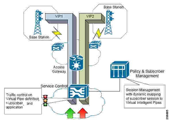
Figure 1-2 shows the overall approach:
- Two VIPs (VIP1 and VIP2) are defined.
- The subscribers and traffic are mapped to the VIP using policy and subscriber management entities.
- You can classify the overall traffic into specific subscribers and applications, and enforce traffic control rules and the VIP control rule.
You can extend the approach described here to a cell-site backhaul link, multiple cell-sites, and so on.
Cell Congestion Awareness
In Cisco Service Control Mobile Solution, the up and down Vlink IDs are retrieved from RADIUS listener attributes, namely upVlinkId and downVlinkID, based on the base station ID. The base station ID is retrieved from the radius.3GPP2_BSID field in the RADIUS packet.
The administrator creates the upstream and downstream Vlinks in Cisco SCE for each base station with corresponding CIR and PIR values of the base station. Each base station ID is mapped to the corresponding Vlink ID in RADIUS upVlinkId and downVlinkId property mapping table, so that subscribers from a particular base station gets their upVlinkId and downVlinkId properties.
Subscriber traffic data is captured by Cisco SCE and appended to the RDRs which is used to generate cell-aware reports.
The following information is sent to the Cisco Service Control Collection Manager in RDRs and used to generate cell congestion reports:
- Up Vlink IDs and Down Vlink IDs, based on the base station ID (for example 3GPP2_BSID) using the Radius Listener LEG.
- Bandwidth used by subscribers.
For more details on creating Vlinks on Cisco SCE, see the “Virtual Link API” section of the Cisco SCE Subscriber API Programmer Guide, Release 4.1.x.
For more details on configuring the RADIUS Listener LEG, see the “Configuring RADIUS Attributes Mapping” section on the Cisco Service Control Subscriber Manager LEGs User Guide, Release 4.1.x.
 Feedback