Cisco SCE Remote Cable MSO Links Solution Guide, Release 4.0.x
Bias-Free Language
The documentation set for this product strives to use bias-free language. For the purposes of this documentation set, bias-free is defined as language that does not imply discrimination based on age, disability, gender, racial identity, ethnic identity, sexual orientation, socioeconomic status, and intersectionality. Exceptions may be present in the documentation due to language that is hardcoded in the user interfaces of the product software, language used based on RFP documentation, or language that is used by a referenced third-party product. Learn more about how Cisco is using Inclusive Language.
- Updated:
- June 25, 2013
Chapter: Configuring the Remote Cable MSO Links Solution
Configuring the Remote Cable MSO Links Solution
Introduction
This chapter describes:
•![]() Basic topology for managing remote cable MSO links and the high-level steps to configure the solution—"Solution Topology" section
Basic topology for managing remote cable MSO links and the high-level steps to configure the solution—"Solution Topology" section
•![]() Prerequisites for configuring a solution that uses traffic optimization on remote links with the VLM—"Prerequisites" section
Prerequisites for configuring a solution that uses traffic optimization on remote links with the VLM—"Prerequisites" section
•![]() Configuring the VLM by using the configuration files contained in the Subscriber Manager installation—"Configuring the Solution" section
Configuring the VLM by using the configuration files contained in the Subscriber Manager installation—"Configuring the Solution" section
Solution Topology
Figure 4-1 shows a system that can be configured for managing remote cable MSO links.
Figure 4-1 Traffic Optimization on Remote Links Topology
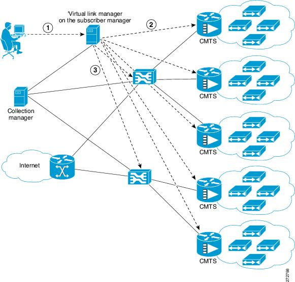

Note ![]() Using a Collection Manager is optional and is not required for the solution to work. However, if you do not use a Collection Manager, the reports provided by the Service Control Application Reporter (SCA Reporter) can be selected only by the virtual link index and not by the virtual link name.
Using a Collection Manager is optional and is not required for the solution to work. However, if you do not use a Collection Manager, the reports provided by the Service Control Application Reporter (SCA Reporter) can be selected only by the virtual link index and not by the virtual link name.
To work with the Collection Manager, you must associate the Cisco Service Control Collection Manager with the Cisco SCE and also with the Subscriber Manager. However, it is not mandatory to associate the Collection Manager with the Subscriber Manager. In this case, the Collection Manager receives the Raw Data Records (RDRs) but does not automatically receive the index to the vlink name mappings.
The operator configures the IP addresses of the CMTS devices, the Cisco SCEs, the Collection Manager, and their interrelations on the Cisco Subscriber Manager (1). The Cisco Subscriber Manager queries each CMTS device through SNMP to determine its sysname, interfaces, and their corresponding interface speeds (2). The Cisco Subscriber Manager provisions the Cisco SCE virtual links (3).
CMTS Device Compatibility
This traffic optimization on remote links solution supports these devices at present:
•![]() Cisco CMTS Universal Broadband Router (uBR)
Cisco CMTS Universal Broadband Router (uBR)
–![]() uBR10K
uBR10K
–![]() uBR7246
uBR7246
•![]() Non-Cisco CMTS
Non-Cisco CMTS
–![]() Arris CMTS
Arris CMTS
To use other CMTS devices, you must ensure that these conditions are met:
•![]() Upstream and downstream interface IDs are encoded as part of option 82, sub option 1 (the circuit ID) and appears in the DHCPACK message.
Upstream and downstream interface IDs are encoded as part of option 82, sub option 1 (the circuit ID) and appears in the DHCPACK message.
•![]() CM-MAC, which is used as the Subscriber-ID, is encoded as option 82, suboption 2 (the remote ID) and appears in the DHCPACK message.
CM-MAC, which is used as the Subscriber-ID, is encoded as option 82, suboption 2 (the remote ID) and appears in the DHCPACK message.
•![]() DHCP traffic flows through the Cisco SCE.
DHCP traffic flows through the Cisco SCE.
•![]() To use Cisco CMTS and non-Cisco CMTS devices for IPDR, you must ensure that these conditions are also met:
To use Cisco CMTS and non-Cisco CMTS devices for IPDR, you must ensure that these conditions are also met:
–![]() The Upstream IDs are retrieved or identified by using CmtsIpv4Addr, CmtsMdIfIndex and CmtsTcsId fields, which is a part of CM registration IPDR messages.
The Upstream IDs are retrieved or identified by using CmtsIpv4Addr, CmtsMdIfIndex and CmtsTcsId fields, which is a part of CM registration IPDR messages.
–![]() The Downstream IDs are retrieved or identified by using CmtsIpv4Addr, CmtsMdIfIndex and CmtsRcsId fileds, which is a part of CM registration IPDR messages.
The Downstream IDs are retrieved or identified by using CmtsIpv4Addr, CmtsMdIfIndex and CmtsRcsId fileds, which is a part of CM registration IPDR messages.
–![]() The Cable Modem MAC address, which is used as Subscriber-ID, is retrieved or identified by CMmacAddress field that is a part of the Cable Modem Registration IPDR messages.
The Cable Modem MAC address, which is used as Subscriber-ID, is retrieved or identified by CMmacAddress field that is a part of the Cable Modem Registration IPDR messages.
Traffic optimization on the remote links solution uses DOCSIS MIBs and standard MIBs.
Prerequisites
Before you set up the managing remote cable MSO links solution, you must complete these tasks:
•![]() Install the Cisco Service Control Subscriber Manager, Cisco Service Control Collection Manager (optional), and Cisco SCE.
Install the Cisco Service Control Subscriber Manager, Cisco Service Control Collection Manager (optional), and Cisco SCE.
•![]() Install the Cisco SCA BB (the Engage pqi file) on the Cisco SCEs used in the solution. See the "How to Install PQI Files on Cisco SCE Devices" section in the "Using the Network Navigator" chapter, of Cisco Service Control Application for Broadband User Guide.
Install the Cisco SCA BB (the Engage pqi file) on the Cisco SCEs used in the solution. See the "How to Install PQI Files on Cisco SCE Devices" section in the "Using the Network Navigator" chapter, of Cisco Service Control Application for Broadband User Guide.
Configuring the Solution
This section describes how to configure the solution.
Configuring Virtual Link Global Controllers
Step 1 ![]() Start the Cisco SCA BB console by choosing Start > All Programs > Cisco SCA > SCA BB Console 4.0.x > SCA BB Console 4.0.x.
Start the Cisco SCA BB console by choosing Start > All Programs > Cisco SCA > SCA BB Console 4.0.x > SCA BB Console 4.0.x.
The Cisco SCA BB Console splash screen appears. After the Console loads, the main window of the Console appears. The first time that you launch the Console, the Welcome view is open in the main window.
Step 2 ![]() To close the Welcome view, click Go to the console. The Welcome view closes. The Network Navigator tool is open in the Console.
To close the Welcome view, click Go to the console. The Welcome view closes. The Network Navigator tool is open in the Console.
Step 3 ![]() From the Console main menu, choose Tools > Service Configuration Editor.
From the Console main menu, choose Tools > Service Configuration Editor.
If no service configurations are open when you open the Service Configuration Editor tool, a No Service Configuration Is Open dialog box appears:
a. ![]() To create a new service configuration, click Yes. A New Service Configuration Settings dialog box appears.
To create a new service configuration, click Yes. A New Service Configuration Settings dialog box appears.
b. ![]() Select an operational mode for the service configuration.
Select an operational mode for the service configuration.
c. ![]() Click OK.
Click OK.
The new service configuration is added to the Console window (Figure 4-2) that becomes the active service configuration.
Figure 4-2 Console Window
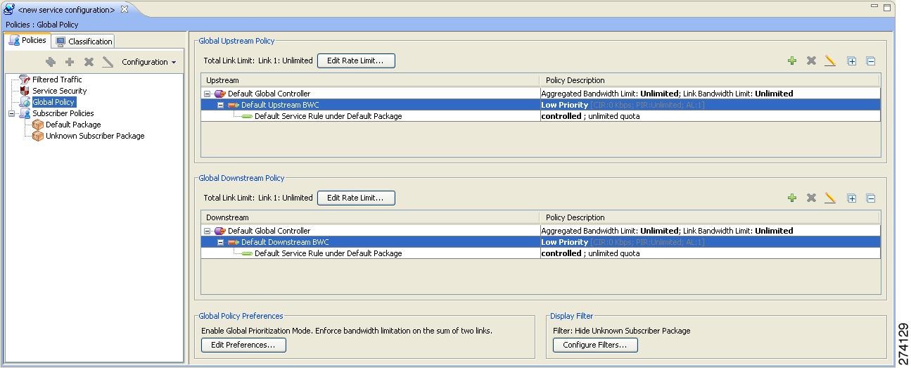
Step 4 ![]() In the Global Policy Preferences area, click Edit Preferences.
In the Global Policy Preferences area, click Edit Preferences.
The Global Controllers mode dialog box appears (Figure 4-3).
Figure 4-3 Global Controllers Mode Dialog Box
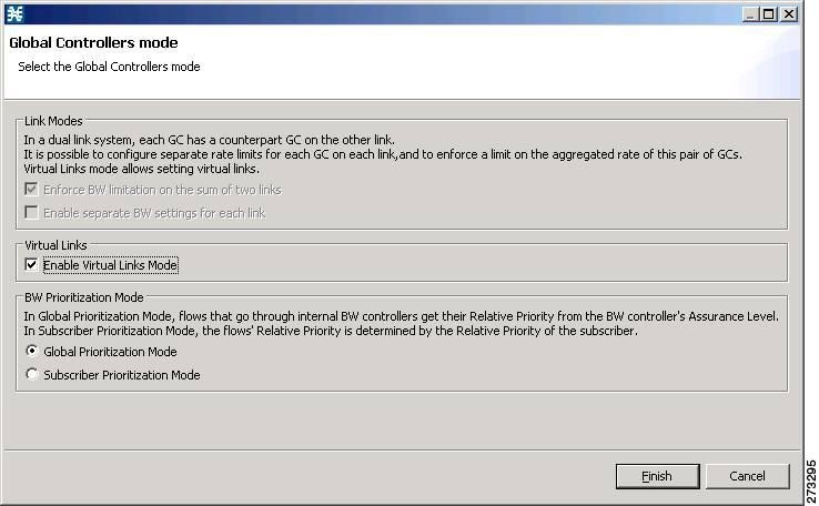
Note ![]() The Virtual Link Mode works only in Subscriber Prioritization Mode by default.
The Virtual Link Mode works only in Subscriber Prioritization Mode by default.
Step 5 ![]() Check the Enable Virtual Links Mode check box.
Check the Enable Virtual Links Mode check box.
The Apply Template rate limits to all Virtual Links? dialog box appears (Figure 4-4).
Figure 4-4 Virtual Links? Dialog Box

Step 6 ![]() Click Reset all Virtual Links to Template rate limits when you change the number of Global Controllers.
Click Reset all Virtual Links to Template rate limits when you change the number of Global Controllers.
If you are applying the template for the first time, always select Rest all Virtual Links. Whenever the template is getting changed with respect to the AGC and the BWC, then use Reset all Virtual Links to Template rate limits. Otherwise, to retain the modified template, use the Keep Virtual Link rate limits unchanged.
Click Keep Virtual Link rate limits unchanged to retain the current Virtual Links rate limits. Only the defined virtual link is set to the new template rate limit.
Step 7 ![]() Click Finish.
Click Finish.
The new service configuration window appears (Figure 4-5).
Figure 4-5 New Service Configuration Window
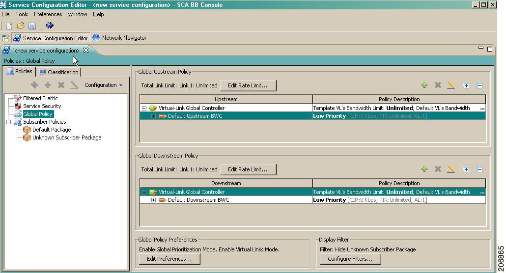
For more information on the Service Configuration Editor, see the Cisco Service Control Application for Broadband User Guide.
Virtual link global controllers can be added, edited, and deleted in the same way as regular global controllers. For more information, see these sections:
•![]() How to Add Global Controllers
How to Add Global Controllers
•![]() How to Add Global Controllers Inside Virtual Link
How to Add Global Controllers Inside Virtual Link
•![]() How to Edit Package Subscriber BWCs
How to Edit Package Subscriber BWCs
How to Add Global Controllers
Note ![]() You can edit the default global controller settings, however, the default instance of global controller cannot be deleted.
You can edit the default global controller settings, however, the default instance of global controller cannot be deleted.
Step 1 ![]() In the Policies tab, click Global Policy.
In the Policies tab, click Global Policy.
The Global Bandwidth Settings dialog box is displayed in the right (Rule) pane.
Step 2 ![]() Above the area (Upstream or Downstream) of the desired interface, click the Add
Above the area (Upstream or Downstream) of the desired interface, click the Add  icon.
icon.
The Select Addition mode dialog box appears (Figure 4-6).
Figure 4-6 Select Addition Mode

Step 3 ![]() To add a new global controller, click the Add a new Global Controller radio button.
To add a new global controller, click the Add a new Global Controller radio button.
Step 4 ![]() Click Next.
Click Next.
The Global Controller Settings dialog box appears. See Figure 4-7.
Note ![]() The display in Figure 4-7 depends on the global controller mode setting.
The display in Figure 4-7 depends on the global controller mode setting.
Figure 4-7 Upstream Global Controller Settings
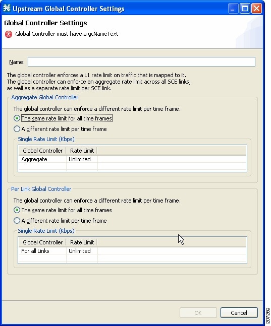
Step 5 ![]() In the Name field, enter a meaningful name.
In the Name field, enter a meaningful name.
Step 6 ![]() Edit the maximum bandwidth of the aggregate and per link global controller rate limits.
Edit the maximum bandwidth of the aggregate and per link global controller rate limits.
Step 7 ![]() Click OK.
Click OK.
Your changes are saved.
The Global Controller Settings dialog box closes.
How to Add Global Controllers Inside Virtual Link
You can create AGCs inside a virtual link global controller.
Note ![]() You can edit the default global controller settings, however, the default instance of global controller cannot be deleted.
You can edit the default global controller settings, however, the default instance of global controller cannot be deleted.
Step 1 ![]() In the Policies tab, click Global Policy.
In the Policies tab, click Global Policy.
The Global Bandwidth Settings dialog box is displayed in the right (Rule) pane.
Step 2 ![]() Above the area (Upstream or Downstream) of the desired interface, click the Add icon.
Above the area (Upstream or Downstream) of the desired interface, click the Add icon.
The Select addition mode dialog box appears (Figure 4-8).
Figure 4-8 Select Addition Mode
Step 3 ![]() To add a new global controller within a virtual link, click the Add a new Global Controller inside Virtual Link radio button.
To add a new global controller within a virtual link, click the Add a new Global Controller inside Virtual Link radio button.
Step 4 ![]() Click Next.
Click Next.
The Global Controller Settings dialog box appears. See Figure 4-9.
Note ![]() The display in Figure 4-9 depends on the global controller mode setting.
The display in Figure 4-9 depends on the global controller mode setting.
Figure 4-9 Upstream Global Controller Settings
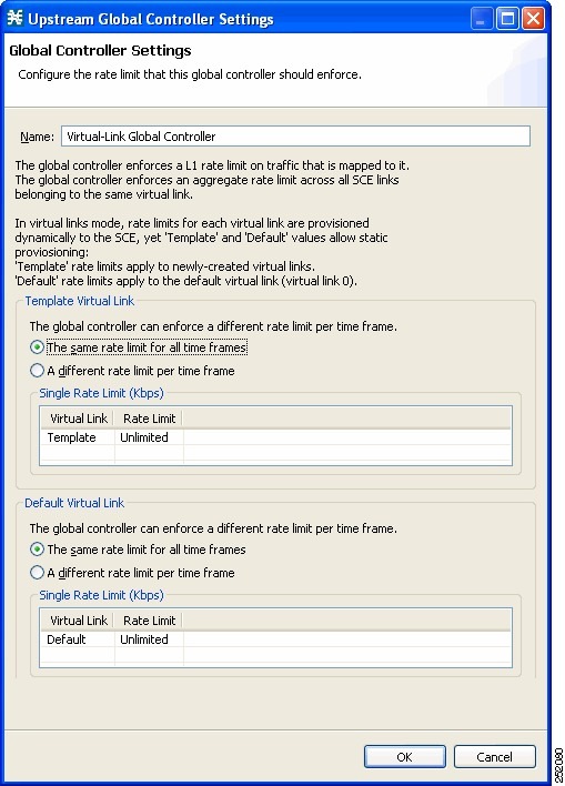
Step 5 ![]() In the Name field enter a meaningful name.
In the Name field enter a meaningful name.
Step 6 ![]() Edit the maximum bandwidth of the template and the default values rate limit
Edit the maximum bandwidth of the template and the default values rate limit
Step 7 ![]() Click OK.
Click OK.
Your changes are saved.
The Global Controller Settings dialog box closes.
How to Edit Package Subscriber BWCs
Step 1 ![]() In the Policies tab, click Global Policy.
In the Policies tab, click Global Policy.
The Global Bandwidth Settings dialog box is displayed in the right (Rule) pane.
Step 2 ![]() In the right (Rule) pane, select a BWC and click the Edit
In the right (Rule) pane, select a BWC and click the Edit icon.
icon.
The Package Settings dialog box appears.
Step 3 ![]() In the Package Settings dialog box, click the Subscriber BW Controllers tab.
In the Package Settings dialog box, click the Subscriber BW Controllers tab.
The Subscriber BW Controllers tab opens. See Figure 4-10.
Figure 4-10 Subscriber BW Controllers Tab
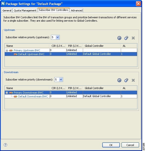
Step 4 ![]() Set your requirements for upstream bandwidth control in the Upstream area of the dialog box.
Set your requirements for upstream bandwidth control in the Upstream area of the dialog box.
a. ![]() Select a value from the Subscriber relative priority drop-down list.
Select a value from the Subscriber relative priority drop-down list.
b. ![]() Set the parameters for the Primary Upstream BWC.
Set the parameters for the Primary Upstream BWC.
–![]() In the CIR field, enter the BWC CIR in Kbps.
In the CIR field, enter the BWC CIR in Kbps.
–![]() In the PIR field, select Unlimited from the drop-down list, or enter the BWC PIR in Kbps.
In the PIR field, select Unlimited from the drop-down list, or enter the BWC PIR in Kbps.
c. ![]() To add BWCs to the package, click the Add a sub BW Controller
To add BWCs to the package, click the Add a sub BW Controller  icon once for each additional BWC.
d. ![]() To add Extra BWCs to the package, click the Add an extra BW Controller
To add Extra BWCs to the package, click the Add an extra BW Controller  icon once for each additional BWC.
e. ![]() Set the parameters for each BWC (including the Primary and Default BWCs).
Set the parameters for each BWC (including the Primary and Default BWCs).
–![]() (Optional) In the Name field, enter a meaningful name for each BWC. (You cannot rename the Primary or Default BWCs.)
(Optional) In the Name field, enter a meaningful name for each BWC. (You cannot rename the Primary or Default BWCs.)
–![]() In the CIR field, enter a value for the BWC CIR in Kbps.
In the CIR field, enter a value for the BWC CIR in Kbps.
–![]() In the PIR field, select Unlimited from the drop-down list, or enter a value for the BWC PIR in Kbps.
In the PIR field, select Unlimited from the drop-down list, or enter a value for the BWC PIR in Kbps.
–![]() To set the global controller with which this BWC is associated, click in the Global Controller cell of the BWC, and then click the Browse button that appears.
To set the global controller with which this BWC is associated, click in the Global Controller cell of the BWC, and then click the Browse button that appears.
The Select a Global Controller dialog box appears. See Figure 4-11.
Figure 4-11 Select a Global Controller Dialog Box
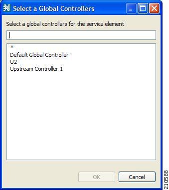
–![]() Select a global controller and click OK.
Select a global controller and click OK.
–![]() Select a value from the AL drop-down list.
Select a value from the AL drop-down list.
Step 5 ![]() Repeat Step 3 for downstream bandwidth control in the Downstream area of the dialog box.
Repeat Step 3 for downstream bandwidth control in the Downstream area of the dialog box.
Step 6 ![]() Click OK.
Click OK.
The Package Settings dialog box closes.
All changes to the BWC settings are saved.
Applying Service Configurations to Cisco SCE Platforms
Step 1 ![]() Using the Network Navigator tool, in the Site Manager tree, right-click an Cisco SCE device. A popup menu appears.
Using the Network Navigator tool, in the Site Manager tree, right-click an Cisco SCE device. A popup menu appears.
Step 2 ![]() From the menu, choose Apply Service Configuration.
From the menu, choose Apply Service Configuration.
The Choose Policy dialog box appears, listing all service configurations that are open in the Service Configuration Editor.
Note ![]() If only one service configuration is open in the Service Configuration Editor, a Password Management dialog box appears. Go to Step 5.
If only one service configuration is open in the Service Configuration Editor, a Password Management dialog box appears. Go to Step 5.
Note ![]() If the open policy is a virtual links policy, the Apply Template Virtual Links Values dialog box prompts you to apply the template virtual links value to the existing virtual links. Go to Step 4.
If the open policy is a virtual links policy, the Apply Template Virtual Links Values dialog box prompts you to apply the template virtual links value to the existing virtual links. Go to Step 4.
Step 3 ![]() Select a service configuration from the list.
Select a service configuration from the list.
Step 4 ![]() Click OK.
Click OK.
To apply the template virtual links value to the existing virtual links, click Yes.
A Password Management dialog box appears.
Step 5 ![]() Enter the appropriate password.
Enter the appropriate password.
Step 6 ![]() Click Apply.
Click Apply.
The Password Management dialog box closes. An Applying service configuration to Cisco SCE progress bar appears. The service configuration is applied to the selected Cisco SCE platform.
Configuring the Virtual Links Manager
Step 1 ![]() On the Subscriber Manager machine, open the p3sm.cfg configuration file, which is located in the ~pcube/sm/server/root/config/ directory.
On the Subscriber Manager machine, open the p3sm.cfg configuration file, which is located in the ~pcube/sm/server/root/config/ directory.
For details about making configuration changes in the p3sm.cfg file, see the "Configuration Files Options" chapter of Cisco Service Control Management Suite Subscriber Manager User Guide.
a. ![]() Create a section for any Cisco SCE devices and define the IP address and optionally the port values of the Cisco SCE devices. This example shows the Cisco SCE sections created for two Cisco SCE devices named SCE1 and SCE2:
Create a section for any Cisco SCE devices and define the IP address and optionally the port values of the Cisco SCE devices. This example shows the Cisco SCE sections created for two Cisco SCE devices named SCE1 and SCE2:
[SCE.SCE1]
ip=209.165.201.2
[SCE.SCE2]
ip=209.165.201.3
b. ![]() (Optional) Create a section for the Collection Manager and define the IP address and the connected Cisco SCE devices. Defining the Collection Manager port value is optional; if a value is not defined, the default value of 14375 is used.
(Optional) Create a section for the Collection Manager and define the IP address and the connected Cisco SCE devices. Defining the Collection Manager port value is optional; if a value is not defined, the default value of 14375 is used.
The following example shows the Collection Manager section created that receives the RDRs for two Cisco SCE devices named SCE1 and SCE2:
[CM.CM1]
ip=209.165.202.129
port=14375
sce_list=SCE1,SCE2
Note ![]() Using a Collection Manager is optional and is not required for the solution to work. However, if you do not use a Collection Manager, all the virtual link reports can be selected only by the virtual link index and not by the virtual link name.
Using a Collection Manager is optional and is not required for the solution to work. However, if you do not use a Collection Manager, all the virtual link reports can be selected only by the virtual link index and not by the virtual link name.
Step 2 ![]() Save and close the p3sm.cfg configuration file.
Save and close the p3sm.cfg configuration file.
Step 3 to Step 6 are applicable only to DHCP Sniffer LEG configuration. If you are using IPDR LEG, proceed to Step 7. Step 7 and Step 8 are applicable only to IPDR LEG.
Step 3 ![]() (Only for DHCP Sniffer LEG) On the Subscriber Manager machine, open the dhcpsnif.cfg configuration file, which is located in the ~pcube/sm/server/root/config/ directory.
(Only for DHCP Sniffer LEG) On the Subscriber Manager machine, open the dhcpsnif.cfg configuration file, which is located in the ~pcube/sm/server/root/config/ directory.
For details about making configuration changes in the dhcpsnif.cfg file, see the "SCE-Sniffer DHCP LEG" section in "Configuring the SCE-Sniffer DHCP LEG" chapter of Cisco Service Control Subscriber Manager LEGs User Guide.
a. ![]() In the [SCE-Sniffer DHCP LEG] section, set the start value to yes.
In the [SCE-Sniffer DHCP LEG] section, set the start value to yes.
[SCE-Sniffer DHCP LEG]
start=yes
All the other values can be left at the default values.
b. ![]() In the [Subscriber ID] section, set the dhcp_option to the DHCP option that contains the subscriber ID and set the dhcp_option_type to binary. For example:
In the [Subscriber ID] section, set the dhcp_option to the DHCP option that contains the subscriber ID and set the dhcp_option_type to binary. For example:
[Subscirber ID]
dhcp_option=82:2
dhcp_option_type=binary
All the other values can be left at the default values.
Step 4 ![]() (Only for DHCP Sniffer LEG) Save and close the dhcpsnif.cfg configuration file.
(Only for DHCP Sniffer LEG) Save and close the dhcpsnif.cfg configuration file.
Step 5 ![]() (Only for DHCP Sniffer LEG) On the Subscriber Manager machine, open the dhcp_pkg.cfg configuration file, which is located in the ~pcube/sm/server/root/config/ directory.
(Only for DHCP Sniffer LEG) On the Subscriber Manager machine, open the dhcp_pkg.cfg configuration file, which is located in the ~pcube/sm/server/root/config/ directory.
For details about modifying configuration in the dhcp_pkg.cfg file, see the "SCE-Sniffer DHCP LEG" section, in "Configuring the SCE-Sniffer DHCP LEG" chapter of Cisco Service Control Subscriber Manager LEGs User Guide.
a. ![]() Define a downstream virtual link policy by setting the parameters:
Define a downstream virtual link policy by setting the parameters:
[DHCP.Policy.VirtualLinkDownstream]
policy_property_name=downVlinkId
options_order_for_policy_name=giaddr,82:1
options_type=integer,binary
allow_login_with_no_policy=true
use_default=false
default_policy=0
Note ![]() Do not define the mapping_table parameter.
Do not define the mapping_table parameter.
b. ![]() Define an upstream virtual link policy by setting the parameters:
Define an upstream virtual link policy by setting the parameters:
[DHCP.Policy.VirtualLinkUpstream]
policy_property_name=upVlinkId
options_order_for_policy_name=giaddr,82:1
options_type=integer,binary
allow_login_with_no_policy=true
use_default=false
default_policy=0
Note ![]() Do not define the mapping_table parameter.
Do not define the mapping_table parameter.
c. ![]() Detect if the subscriber is related to the DOCSIS 3.0 wideband interface
Detect if the subscriber is related to the DOCSIS 3.0 wideband interface
–![]() The attribute related to [DHCP.Policy.VirtualLinkUpstream] and [DHCP.Policy.VirtualLinkDownstream] parameters is docsis_3_cm_detection. The value of attribute is Modem_Type.DOCSIS3.0.
The attribute related to [DHCP.Policy.VirtualLinkUpstream] and [DHCP.Policy.VirtualLinkDownstream] parameters is docsis_3_cm_detection. The value of attribute is Modem_Type.DOCSIS3.0.
Note ![]() It is mandatory to enter values for the Modem_Type.DOCSIS3.0 field.
It is mandatory to enter values for the Modem_Type.DOCSIS3.0 field.
docsis_3_cm_detection=Modem_Type.DOCSIS3
d. ![]() Set the rules to define DHCP data coming from the DOCSIS 3.0 cable modem interface
Set the rules to define DHCP data coming from the DOCSIS 3.0 cable modem interface
–![]() To identify if DOCSIS 3.0 is the cable modem type, use this parameter:
To identify if DOCSIS 3.0 is the cable modem type, use this parameter:
[Modem_Type.DOCSIS3.0]
This parameter has two attributes—option and option_type.
The format of the parameter is the option number itself. But for DHCP options with sub-options, the format is the DHCP option and sub-option type separated by a colon.
For example:
# 43:123 or 61
(default option 67, "Boot filename")
option=67
–![]() The format type of DHCP option is defined by the 'dhcp_option' parameter. Optional values are 'binary' (binary string that is converted to an ASCII hexadecimal string) or 'string' (ASCII string). The default value is string.
The format type of DHCP option is defined by the 'dhcp_option' parameter. Optional values are 'binary' (binary string that is converted to an ASCII hexadecimal string) or 'string' (ASCII string). The default value is string.
option_type=string
–![]() The parameter to define the search pattern to verify that the cable modem belongs to DOCSIS 3.0 is option_pattern. The value for this parameter is a single regular expression pattern per dhcp_option. If there are more than one dhcp_option, the values for option_pattern is a list of regular expression patterns (one pattern per option) separated by comma. The default value is 3.0.
The parameter to define the search pattern to verify that the cable modem belongs to DOCSIS 3.0 is option_pattern. The value for this parameter is a single regular expression pattern per dhcp_option. If there are more than one dhcp_option, the values for option_pattern is a list of regular expression patterns (one pattern per option) separated by comma. The default value is 3.0.
option_pattern=3.0
Step 6 ![]() (Only for DHCP Sniffer LEG) Save and close the dhcp_pkg.cfg configuration file.
(Only for DHCP Sniffer LEG) Save and close the dhcp_pkg.cfg configuration file.
Note ![]() When the VLM is activated, the DHCP sniffer adds a custom property to each subscriber with the value of the giaddr option, which is one of the CMTS IP addresses.
When the VLM is activated, the DHCP sniffer adds a custom property to each subscriber with the value of the giaddr option, which is one of the CMTS IP addresses.
Step 7 ![]() (Only for IPDR LEG) Configure the file <pcube>/sm/server/root/config/ipdr.cfg.
(Only for IPDR LEG) Configure the file <pcube>/sm/server/root/config/ipdr.cfg.
CM Mac Address will be the default Subscriber ID. The CMTS Name should be mapped to the CMTS Name configured in vlink.cfg.
IPDR LEG supports both static and dynamic mappings. If there are any conflicts, dynamic mappings learnt from the CMTS will be considered for subscriber association. The start parameter in the IPDR LEG configuration section defines whether the VLM is enabled or disabled. The default value is "no". If you enable VLM, the VLM starts learning the device topology defined in the configuration file and starts the dynamic VLINK assignments on the relevant Cisco SCEs. You must manually create the VLINKs and AGCs in the Cisco SCE, for the static mappings you configure in the ipdr.cfg.
This is an example of the configuration:
[IPDR LEG]
start=yes
log_failures=yes
log_all=no
# Enable the below option to log the receiving IPDR messages
# (Default value: false)
# log_subs_details=false
# Enable the below option to log the mapping table information
# (Default value: false)
# log_mapping_table=false
# Enable the below option to log the subscribers who are partially logging in
# (Default value: false)
# log_login_partial_subs=false
cm_mode=no
#CM Mac Address will be the default Subscriber ID
[IPDR.Subscriber ID]
fields=CMmacAddress
[IPDR.Field.CMmacAddress]
ipdr_key=CmMacAddr
ipdr_key_type=string
#Configure IPDR Exporter
# [IPDR.Exporter.<CMTS NAME>]
# The CMTS Name should mapped to the CMTS Name configured in vlink.cfg
[IPDR.Exporter.CMTS1]
start_exporter=yes
exporter_connection_type=active
connection_time_out=100
keep_alive=15
port=4737
# Configure the sesion ids specified in the exporter.
#session_id=<session_id>,<session_id>
session_id=2,3,4
Step 8 ![]() (Only for IPDR LEG) If the host entry is not added in the Subscriber Manager, then add the IPDR Collector IP address to the ipdr.cfg.
(Only for IPDR LEG) If the host entry is not added in the Subscriber Manager, then add the IPDR Collector IP address to the ipdr.cfg.
Example:
CMTS(config)# ipdr collector dt-sm-linux 10.78.242.22
Step 9 ![]() On the Subscriber Manager machine, open the vlink.cfg configuration file, which is located in the ~pcube/sm/server/root/config/ directory.
On the Subscriber Manager machine, open the vlink.cfg configuration file, which is located in the ~pcube/sm/server/root/config/ directory.
a. ![]() In the [General] section, configure these parameters:
In the [General] section, configure these parameters:
–![]() start—Setting the start parameter to yes instructs the Subscriber Manager to start the VLM when the Subscriber Manager starts. Possible values for this parameter are yes and no.
start—Setting the start parameter to yes instructs the Subscriber Manager to start the VLM when the Subscriber Manager starts. Possible values for this parameter are yes and no.
Note ![]() When the start parameter is set to no, the data stored in the database for all CMTS devices is deleted.
When the start parameter is set to no, the data stored in the database for all CMTS devices is deleted.
–![]() monitoring_period—Determines the interval in minutes at which the VLM queries the CMTS devices for any interface changes. Setting this parameter to 0 stops the VLM querying the CMTS devices, but does not stop the VLM. The default value is 60.
monitoring_period—Determines the interval in minutes at which the VLM queries the CMTS devices for any interface changes. Setting this parameter to 0 stops the VLM querying the CMTS devices, but does not stop the VLM. The default value is 60.
–![]() ignore_duplicate_ip—Ignores the duplicate IP in the ipAddrTable of the configured CMTS. The default value is false. Possible values are true and false.
ignore_duplicate_ip—Ignores the duplicate IP in the ipAddrTable of the configured CMTS. The default value is false. Possible values are true and false.
–![]() upstream_vlink_factor—Determines the percentage of the interface bandwidth that Cisco SCE allows to be sent from the CMTS device to the Internet. The default value is 95.
upstream_vlink_factor—Determines the percentage of the interface bandwidth that Cisco SCE allows to be sent from the CMTS device to the Internet. The default value is 95.
–![]() downstream_vlink_factor—Determines the percentage of the interface bandwidth that the Cisco SCE allows to be sent from the Internet to the CMTS device. The default value is 95.
downstream_vlink_factor—Determines the percentage of the interface bandwidth that the Cisco SCE allows to be sent from the Internet to the CMTS device. The default value is 95.
Note ![]() When defining the upstream_vlink_factor and downstream_vlink_factor parameters, take precaution. Setting a very low value causes wastage of bandwidth capacity. Setting a very high value causes data loss because of dropped packets.
When defining the upstream_vlink_factor and downstream_vlink_factor parameters, take precaution. Setting a very low value causes wastage of bandwidth capacity. Setting a very high value causes data loss because of dropped packets.
Note ![]() Whenever you change the default values of upstream_vlink_factor and downstream_vlink_factor, you must manually resync the vlink information by using the p3vlink --resync-all command to reflect the changes on all Cisco SCEs.
Whenever you change the default values of upstream_vlink_factor and downstream_vlink_factor, you must manually resync the vlink information by using the p3vlink --resync-all command to reflect the changes on all Cisco SCEs.
–![]() log_all—Setting the log_all parameter to true causes the system to dump log messages to the user log.
log_all—Setting the log_all parameter to true causes the system to dump log messages to the user log.
–![]() upstream_global_controller_list—Determines the list of non default upstream global controllers, which are defined in the template and managed by VLM.
upstream_global_controller_list—Determines the list of non default upstream global controllers, which are defined in the template and managed by VLM.
–![]() downstream_global_controller_list—Determines the list of non default downstream global controllers, which are defined in the template and managed by VLM.
downstream_global_controller_list—Determines the list of non default downstream global controllers, which are defined in the template and managed by VLM.
For more information, see the "Configuring Virtual Link Global Controllers" section.
Note ![]() Every global controller defined in the configuration file should exist in the policy configuration.
Every global controller defined in the configuration file should exist in the policy configuration.
–![]() upstream_global_controller_pir_percentage—(Optional) Determines the percentage of the PIR values of the wideband interfaces. One or more PIR values can be configured, each value corresponds to the global controller that belongs to the global controller list.
upstream_global_controller_pir_percentage—(Optional) Determines the percentage of the PIR values of the wideband interfaces. One or more PIR values can be configured, each value corresponds to the global controller that belongs to the global controller list.
Note ![]() If the PIR values are not configured, then the default PIR values are used to determine the percentage.
If the PIR values are not configured, then the default PIR values are used to determine the percentage.
–![]() downstream_global_controller_pir_percentage—(Optional) Determines the percentage of the PIR values of the wideband interfaces. One or more PIR values can be configured, each value corresponds to the global controller that belongs to the global controller list.
downstream_global_controller_pir_percentage—(Optional) Determines the percentage of the PIR values of the wideband interfaces. One or more PIR values can be configured, each value corresponds to the global controller that belongs to the global controller list.
–![]() enable_dynamic_giaddrs_learning—(Optional) Avoids learning new giaddrs during log in. If this value is set to false, if the Cisco Subscriber Manager identifies during the login that the relay agent does not belong to a known CMTS, the Cisco Subscriber Manager ignores the query and continues with the login. This functionality is applicable only for static device configuration. The default value is true.
enable_dynamic_giaddrs_learning—(Optional) Avoids learning new giaddrs during log in. If this value is set to false, if the Cisco Subscriber Manager identifies during the login that the relay agent does not belong to a known CMTS, the Cisco Subscriber Manager ignores the query and continues with the login. This functionality is applicable only for static device configuration. The default value is true.
–![]() general_default_cli_integrated— Defines a default integrated CLI that is executed in the device. The default value is show controllers Integrated-Cable card ? association.
general_default_cli_integrated— Defines a default integrated CLI that is executed in the device. The default value is show controllers Integrated-Cable card ? association.
–![]() general_default_cli_modular— Defines a default modular CLI that is executed in the device. The default value is show hw-module bay ? config wideband-channel.
general_default_cli_modular— Defines a default modular CLI that is executed in the device. The default value is show hw-module bay ? config wideband-channel.
–![]() general_default_cli_3g_60—Defines a default 3G60 CLI that is executed in the device. The default value is show controllers Modular-Cable card ? association.
general_default_cli_3g_60—Defines a default 3G60 CLI that is executed in the device. The default value is show controllers Modular-Cable card ? association.
–![]() encrypt_cmts_credentials— Defines whether the CMTS credentials are encrypted or plaintext. The default values is true.
encrypt_cmts_credentials— Defines whether the CMTS credentials are encrypted or plaintext. The default values is true.
–![]() num_of_retry_attempts_for_device_login— Defines the maximum number of times the VLM must try to connect to the device. The default value is 3.
num_of_retry_attempts_for_device_login— Defines the maximum number of times the VLM must try to connect to the device. The default value is 3.
–![]() wait_for_device_uptime—Defines the minimum period to wait after the device is restarted, in minutes. Virtual Link Manager checks the sysUpTime of the Device before starting the query, If it is less than the configured value, then the query to that device is ignored. Valid range is from 0 to 60. The default value is 0.
wait_for_device_uptime—Defines the minimum period to wait after the device is restarted, in minutes. Virtual Link Manager checks the sysUpTime of the Device before starting the query, If it is less than the configured value, then the query to that device is ignored. Valid range is from 0 to 60. The default value is 0.
–![]() access_timeout_for_device_login— Defines the number access timeout in milliseconds. The default value is 10000 milliseconds. If the maximum number of retry attempts is five, and the interval between retrying connections is three minutes or less, the VLM server tries to connect to the device five times with an interval of three minutes between each attempt. The VLM server does not try to connect after 15 minutes.
access_timeout_for_device_login— Defines the number access timeout in milliseconds. The default value is 10000 milliseconds. If the maximum number of retry attempts is five, and the interval between retrying connections is three minutes or less, the VLM server tries to connect to the device five times with an interval of three minutes between each attempt. The VLM server does not try to connect after 15 minutes.
–![]() import_subs_into_db_on_device_add—Defines whether to import all cable modem MAC addresses and the associated CMTS IP addresses to the database when the VLM detects that a new CMTS is added to the topology. Possible values are true and false. The default value is false.
import_subs_into_db_on_device_add—Defines whether to import all cable modem MAC addresses and the associated CMTS IP addresses to the database when the VLM detects that a new CMTS is added to the topology. Possible values are true and false. The default value is false.
–![]() time_interval_for_periodic_snmp_bg_query—Defines the interval, in minutes, at which the corresponding LEG should initiate a bulk query for all subscribers at various VLink modes (partialvlinkmappings, fullvlinkmappings, all). The default value is 0 minutes. The minimum possible value is 2 minutes. By default, this parameter is disabled.
time_interval_for_periodic_snmp_bg_query—Defines the interval, in minutes, at which the corresponding LEG should initiate a bulk query for all subscribers at various VLink modes (partialvlinkmappings, fullvlinkmappings, all). The default value is 0 minutes. The minimum possible value is 2 minutes. By default, this parameter is disabled.
–![]() vlink_mode_for_periodic_snmp_bg_query—Defines whether to query for subscribers with partial VLink mappings, full VLink mappings, and all. Possible values are none, partialvlinkmappings, fullvlinkmappings, all. The default value is none.
vlink_mode_for_periodic_snmp_bg_query—Defines whether to query for subscribers with partial VLink mappings, full VLink mappings, and all. Possible values are none, partialvlinkmappings, fullvlinkmappings, all. The default value is none.
–![]() subscriber_mode_for_periodic_snmp_bg_query—Defines whether to query all subscribers or subscribers based on the DOCSIS version. Possible values are DOCSIS2.0, DOCSIS3.0, all. The default value is all.
subscriber_mode_for_periodic_snmp_bg_query—Defines whether to query all subscribers or subscribers based on the DOCSIS version. Possible values are DOCSIS2.0, DOCSIS3.0, all. The default value is all.
Note ![]() Setting log_all to true can cause performance degradation.
Setting log_all to true can cause performance degradation.
This example shows the [General] section of the vlink.cfg configuration file:
[General]
start=true
monitoring_period=60
upstream_vlink_factor=95
downstream_vlink_factor=95
log_all=false
upstream_global_controller_list=agc_a, agc_b
downstream_global_controller_list=agc_d, agc_e
upstream_global_controller_pir_percentage=80,90
downstream_global_controller_pir_percentage=85,85
enable_dynamic_giaddrs_learning=true
encrypt_cmts_credentials=true
num_of_retry_attempts_for_device_login=3
access_timeout_for_device_login=10000
b. ![]() Modify the Cisco SCE container such that it loads all Cisco SCE IP addresses specified in vlink.cfg as sceIPs in cache. This confirms that VLM integration is done for the DHCP packets only if the packets comes from those Cisco SCEs that are part of the VLM configuration (vlink.cfg).
Modify the Cisco SCE container such that it loads all Cisco SCE IP addresses specified in vlink.cfg as sceIPs in cache. This confirms that VLM integration is done for the DHCP packets only if the packets comes from those Cisco SCEs that are part of the VLM configuration (vlink.cfg).
c. ![]() For each CMTS device, configure a [Device.<device name>] section with these parameters:
For each CMTS device, configure a [Device.<device name>] section with these parameters:
Note ![]() <device name> of the section is used as part of the virtual link name for all virtual links associated with this CMTS device. The name of the CMTS device also appears in the reporter.
<device name> of the section is used as part of the virtual link name for all virtual links associated with this CMTS device. The name of the CMTS device also appears in the reporter.
–![]() device_type—Specifies whether CMTS device is a Cisco CMTS or a non-Cisco CMTS. Possible values are, cisco and arris. The default value is cisco.
device_type—Specifies whether CMTS device is a Cisco CMTS or a non-Cisco CMTS. Possible values are, cisco and arris. The default value is cisco.
–![]() ip—Specifies the IP address of the CMTS device.
ip—Specifies the IP address of the CMTS device.
–![]() sce_name—Specifies the name of the Cisco SCE to which the CMTS device is connected. This must match an Cisco SCE section defined in the p3sm.cfg configuration file.
sce_name—Specifies the name of the Cisco SCE to which the CMTS device is connected. This must match an Cisco SCE section defined in the p3sm.cfg configuration file.
–![]() ignore_upvlink_ids—Specifies the configured UpVlink IDs to be ignored by the Cisco Subscriber Manager while removing the IDs from Cisco SCE. Users should ensure that the configured IDs are not assigned to any of the channels or virtual links by the Subscriber Manager and not provisioned to Cisco SCE. The VLink ID value must be an integer. The values can be separated by a comma (,) or can be a range of values separated by an en dash (-) can be mentioned, as shown in the following example:
ignore_upvlink_ids—Specifies the configured UpVlink IDs to be ignored by the Cisco Subscriber Manager while removing the IDs from Cisco SCE. Users should ensure that the configured IDs are not assigned to any of the channels or virtual links by the Subscriber Manager and not provisioned to Cisco SCE. The VLink ID value must be an integer. The values can be separated by a comma (,) or can be a range of values separated by an en dash (-) can be mentioned, as shown in the following example:
ignore_upvlink_ids= 11,12,15-20
–![]() ignore_downvlink_ids—Specifies the configured DownVlink IDs to be ignored by the Subscriber Manager while removing the IDs from Cisco SCE. Users should ensure that the configured ID's are not assigned to any of the channels or virtual links by the Subscriber Manager and not provisioned to Cisco SCE. The VLink ID value must be an integer. The values can be separated by a comma (,). Alternatively, a range of values can be separated by an en dash (-) as shown in the following example:
ignore_downvlink_ids—Specifies the configured DownVlink IDs to be ignored by the Subscriber Manager while removing the IDs from Cisco SCE. Users should ensure that the configured ID's are not assigned to any of the channels or virtual links by the Subscriber Manager and not provisioned to Cisco SCE. The VLink ID value must be an integer. The values can be separated by a comma (,). Alternatively, a range of values can be separated by an en dash (-) as shown in the following example:
ignore_downvlink_ids= 5-15
–![]() upstream_vlink_factor—(Optional) Determines the percentage of the interface bandwidth that the Cisco SCE allows to be sent from this CMTS device to the Internet. Setting this parameter overrides the setting in the [General] section. If it is not configured, the value defined in the [General] section is used. The default value is 95.
upstream_vlink_factor—(Optional) Determines the percentage of the interface bandwidth that the Cisco SCE allows to be sent from this CMTS device to the Internet. Setting this parameter overrides the setting in the [General] section. If it is not configured, the value defined in the [General] section is used. The default value is 95.
–![]() downstream_vlink_factor—(Optional) Determines the percentage of the interface bandwidth that the Cisco SCE allows to be sent from the Internet to this CMTS device. Setting this parameter overrides the setting in the [General] section. If it is not configured, the value defined in the [General] section is used. The default value is 95.
downstream_vlink_factor—(Optional) Determines the percentage of the interface bandwidth that the Cisco SCE allows to be sent from the Internet to this CMTS device. Setting this parameter overrides the setting in the [General] section. If it is not configured, the value defined in the [General] section is used. The default value is 95.
–![]() log_all—Setting the log_all parameter to true causes the system to dump log messages to the user log for this CMTS device. If the log_all parameter in the [General] section is true, setting this parameter to false has no effect; if the log_all parameter in the [General] section is false, setting this parameter to true enables logging for operations related only to this CMTS device; such as, CMTS device creation and deletion.
log_all—Setting the log_all parameter to true causes the system to dump log messages to the user log for this CMTS device. If the log_all parameter in the [General] section is true, setting this parameter to false has no effect; if the log_all parameter in the [General] section is false, setting this parameter to true enables logging for operations related only to this CMTS device; such as, CMTS device creation and deletion.
–![]() upstream_global_controller_list—(Optional) Determines the list of non default upstream global controllers, which are defined in the template and managed by the VLM. If it is not configured, the value defined in the [General] section is used.
upstream_global_controller_list—(Optional) Determines the list of non default upstream global controllers, which are defined in the template and managed by the VLM. If it is not configured, the value defined in the [General] section is used.
–![]() downstream_global_controller_list—(Optional) Determines the list of non default downstream global controllers, which are defined in the template and managed by the VLM. If it is not configured, the value defined in the [General] section is used.
downstream_global_controller_list—(Optional) Determines the list of non default downstream global controllers, which are defined in the template and managed by the VLM. If it is not configured, the value defined in the [General] section is used.
Note ![]() Every global controller defined in the configuration file should exist in the policy configuration.
Every global controller defined in the configuration file should exist in the policy configuration.
–![]() upstream_global_controller_pir_percentage—(Optional) Determines the percentage of the PIR values of the wideband interfaces. One or more PIR values can be configured, each value corresponds to the global controller that belongs to the global controller list. If it is not configured, the value defined in the [General] section is used.
upstream_global_controller_pir_percentage—(Optional) Determines the percentage of the PIR values of the wideband interfaces. One or more PIR values can be configured, each value corresponds to the global controller that belongs to the global controller list. If it is not configured, the value defined in the [General] section is used.
Note ![]() If the PIR values are not configured, then the default PIR values are used to determine the percentage.
If the PIR values are not configured, then the default PIR values are used to determine the percentage.
–![]() downstream_global_controller_pir_percentage—(Optional) Determines the percentage of the PIR values of the wideband interfaces. One or more PIR values can be configured, each value corresponds to the global controller that belongs to the global controller list. If it is not configured, the value defined in the [General] section is used.
downstream_global_controller_pir_percentage—(Optional) Determines the percentage of the PIR values of the wideband interfaces. One or more PIR values can be configured, each value corresponds to the global controller that belongs to the global controller list. If it is not configured, the value defined in the [General] section is used.
–![]() snmp_community—Specifies the SNMP community value for the VLM to communicate with the CMTS device. The default value is public.
snmp_community—Specifies the SNMP community value for the VLM to communicate with the CMTS device. The default value is public.
–![]() snmp_port—Specifies the SNMP port on which the VLM communicates to the CMTS device. The default value is 161.
snmp_port—Specifies the SNMP port on which the VLM communicates to the CMTS device. The default value is 161.
–![]() giaddr_external—For each giaddr value, the VLM creates a policy mapping table in the DHCP LEG without waiting for a login from the giaddr values. Use this parameter to insert giaddr values to the mapping table that the VLM created after querying the CMTS device. Use a comma "," delimiter between IP addresses. The default value for this parameter is empty.
giaddr_external—For each giaddr value, the VLM creates a policy mapping table in the DHCP LEG without waiting for a login from the giaddr values. Use this parameter to insert giaddr values to the mapping table that the VLM created after querying the CMTS device. Use a comma "," delimiter between IP addresses. The default value for this parameter is empty.
–![]() giaddr_replace—Specifies whether the VLM uses the IP addresses defined in the giaddr_external parameter as the only giaddr list of the CMTS device. When this parameter is set to no, the VLM uses the IP addresses defined in giaddr_external and the giaddr list that is found when querying the CMTS device as the CMTS giaddr list. Possible values for this parameter are yes and no. The default value is no.
giaddr_replace—Specifies whether the VLM uses the IP addresses defined in the giaddr_external parameter as the only giaddr list of the CMTS device. When this parameter is set to no, the VLM uses the IP addresses defined in giaddr_external and the giaddr list that is found when querying the CMTS device as the CMTS giaddr list. Possible values for this parameter are yes and no. The default value is no.
–![]() giaddr_remove—Removes a list of IPs from the mapping table that the VLM created after querying the CMTS device. For each giaddr value, the VLM creates a policy mapping table in the DHCP LEG without waiting for a login from the giaddr values. Use a comma "," delimiter between the IP addresses.
giaddr_remove—Removes a list of IPs from the mapping table that the VLM created after querying the CMTS device. For each giaddr value, the VLM creates a policy mapping table in the DHCP LEG without waiting for a login from the giaddr values. Use a comma "," delimiter between the IP addresses.
–![]() cli_integrated—Defines an optional value the VLM uses to communicate with the device. This attribute loads the general_default_cli_integrated property in general section. The default value is show controllers Integrated-Cable card ? association.
cli_integrated—Defines an optional value the VLM uses to communicate with the device. This attribute loads the general_default_cli_integrated property in general section. The default value is show controllers Integrated-Cable card ? association.
For parsing the CLI, the output of wideband to bonding group mapping is expected to be in a specific format. The line with wideband to bonding group information must start with "Wideband-Cable". After the wideband cable, the ifDescription and the bonding group ID separated by a space. For example, Wideband-Cable1/1/0:0 33, Wideband-Cable7/1/0:0 1057.
–![]() cli_modular—Defines an optional value the VLM uses to communicate with the device. This attribute loads the general_default_cli_modular property in general section. The default value is show hw-module bay ? config wideband-channel.
cli_modular—Defines an optional value the VLM uses to communicate with the device. This attribute loads the general_default_cli_modular property in general section. The default value is show hw-module bay ? config wideband-channel.
–![]() cli_3g60—This attribute overloads the general_default_cli_3g_60 property in general section. The default value is show controllers Modular-Cable card ? association.
cli_3g60—This attribute overloads the general_default_cli_3g_60 property in general section. The default value is show controllers Modular-Cable card ? association.
–![]() integrated_interface_name—Defines the interface name format of the integrated cable that appears in the ifDescr. By default the interface name supported is Integrated-Cable7/1/0:0 (Integrated-Cable<slot/subslot/port>:<channelNo>). If the interface name is Integrated-Cable7/1/0-downstream0, configure the "integrated_interface_name" parameter as Integrated-Cable<slot/subslot/port>-downstream<channelNo>. You can also confugure two or more formats by entering the values seperated by a comma.
integrated_interface_name—Defines the interface name format of the integrated cable that appears in the ifDescr. By default the interface name supported is Integrated-Cable7/1/0:0 (Integrated-Cable<slot/subslot/port>:<channelNo>). If the interface name is Integrated-Cable7/1/0-downstream0, configure the "integrated_interface_name" parameter as Integrated-Cable<slot/subslot/port>-downstream<channelNo>. You can also confugure two or more formats by entering the values seperated by a comma.
–![]() modular_interface_name—Defines the interface name format of the modular cable that appears in the ifDescr. By default the interface name supported is Modular-Cable1/0/0:0 (Modular-Cable<slot/subslot/port>:<channelNo>). If the interface name is Modular-Cable1/0/0-downstream0, configure the "modular_interface_name" parameter as Modular-Cable<slot/subslot/port>-downstream<channelNo>. You can also confugure two or more formats by entering the values seperated by a comma.
modular_interface_name—Defines the interface name format of the modular cable that appears in the ifDescr. By default the interface name supported is Modular-Cable1/0/0:0 (Modular-Cable<slot/subslot/port>:<channelNo>). If the interface name is Modular-Cable1/0/0-downstream0, configure the "modular_interface_name" parameter as Modular-Cable<slot/subslot/port>-downstream<channelNo>. You can also confugure two or more formats by entering the values seperated by a comma.
–![]() ignore_periodic_device_query—Defines whether to enable the VLM periodic SNMP query for topology learning for a specific CMTS. The default value is false.
ignore_periodic_device_query—Defines whether to enable the VLM periodic SNMP query for topology learning for a specific CMTS. The default value is false.
–![]() vlink_mode_for_periodic_snmp_bg_query—Defines whether to query for subscribers with partial VLink mappings, full VLink mappings, and all. Configuring this parameter overrides the global configuration for the device. Possible values are none, partialvlinkmappings, fullvlinkmappings, all. The default value is none.
vlink_mode_for_periodic_snmp_bg_query—Defines whether to query for subscribers with partial VLink mappings, full VLink mappings, and all. Configuring this parameter overrides the global configuration for the device. Possible values are none, partialvlinkmappings, fullvlinkmappings, all. The default value is none.
–![]() enable_dynamic_bg—(Applicable only for Arris CMTS) Defines whether to learn dynamically created bonding group. Possible values are true and false. The default value is false.
enable_dynamic_bg—(Applicable only for Arris CMTS) Defines whether to learn dynamically created bonding group. Possible values are true and false. The default value is false.
Note ![]() Because the channels in a MAC domain may be shared with more than one dynamic bonding group, we recommend that you check the vlink reports at the MAC domain level. We also recommend that you set the number of bonding groups or channels within the Cisco SCE limit.
Because the channels in a MAC domain may be shared with more than one dynamic bonding group, we recommend that you check the vlink reports at the MAC domain level. We also recommend that you set the number of bonding groups or channels within the Cisco SCE limit.
–![]() show_vlink_with_macdomain_name—Defines whether to show the name of the MAC domain or the index of the MAC domain in vlink names and channel names. Possible values are true or false.
show_vlink_with_macdomain_name—Defines whether to show the name of the MAC domain or the index of the MAC domain in vlink names and channel names. Possible values are true or false.
This example shows the [Device.<device name>] section of the vlink.cfg configuration file:
[Device.CMTS1]
ip=192.0.2.10
sce_name=SCE1
ignore_upvlink_ids=11,12,15-20
ignore_downvlink_ids=5-15
log_all=false
upstream_global_controller_list=agc_a, agc_b
downstream_global_controller_list=agc_d, agc_e
upstream_global_controller_pir_percentage=80,90
downstream_global_controller_pir_percentage=85,85
This example shows the option for disabling periodic topology learning of VLM:
[Device.CMTS1]
ip=<192.0.2.10>
sce_name=<SCE1>
log_all=true
port=161
snmp_community=public
ignore_periodic_device_query=true
d. ![]() To support DOCSIS 3.0 channel in Cisco devices, VLM queries the devices for bonding group association by using Telnet or SSH. To query the devices, VLM requires the device credentials. To provide the VLM with device credentials, complete the next two steps:
To support DOCSIS 3.0 channel in Cisco devices, VLM queries the devices for bonding group association by using Telnet or SSH. To query the devices, VLM requires the device credentials. To provide the VLM with device credentials, complete the next two steps:
–![]() Create an input CSV file, (for example, import.csv), with values in the format CMTS_IP,username,password,enable_password,protocol,port with separate line for each device.
Create an input CSV file, (for example, import.csv), with values in the format CMTS_IP,username,password,enable_password,protocol,port with separate line for each device.
–![]() Import the credentials to VLM by using the p3vlink --import-cmts-details CLU.
Import the credentials to VLM by using the p3vlink --import-cmts-details CLU.
If the credentials are wrong, or if the device is not reachable on the configured port using the configured protocol, then the VLINK for DOCSIS 3.0 interfaces is not created and the CMTS supports only DOCSIS 2.0.
This example shows a sample input CSV file with 2 devices configured.
#cmtsip,username,loginpass,enablpass,protocol,port
10.52.26.22,cisco,cisco,cisco,telnet,23
10.52.26.21,cisco,cisco,cisco,telnet,23
If there is no enable password, the enable_password field can be " 0 ".
e. ![]() Configure a device template that enables the users to define the dynamic device behavior. For more information on creating dynamic device, see the "Dynamic GIADDR Learning" section.
Configure a device template that enables the users to define the dynamic device behavior. For more information on creating dynamic device, see the "Dynamic GIADDR Learning" section.
The required parameters are:
–![]() start—Setting the start parameter to yes instructs the VLM to create a dynamic device template. Possible values for this parameter are yes and no.
start—Setting the start parameter to yes instructs the VLM to create a dynamic device template. Possible values for this parameter are yes and no.
If start is set to false, the VLM does not create a dynamic device. Changing the start value from true to false, disables the creation of dynamic device and the VLM deletes all the dynamic devices and their relevant data from the database.
–![]() log_all—Setting the log_all parameter to true causes the system to dump log messages to the user log for this CMTS device. If the log_all parameter in the [General] section is true, setting this parameter to false has no effect; if the log_all parameter in the [General] section is false, setting this parameter to true enables logging for operations related only to this CMTS device, such as, CMTS device creation and deletion.
log_all—Setting the log_all parameter to true causes the system to dump log messages to the user log for this CMTS device. If the log_all parameter in the [General] section is true, setting this parameter to false has no effect; if the log_all parameter in the [General] section is false, setting this parameter to true enables logging for operations related only to this CMTS device, such as, CMTS device creation and deletion.
–![]() snmp_port—(Optional) Specifies the SNMP port value for the VLM to communicate with the CMTS device. The default value is 161.
snmp_port—(Optional) Specifies the SNMP port value for the VLM to communicate with the CMTS device. The default value is 161.
–![]() snmp_community—(Optional) Specifies the SNMP community value for the VLM to communicate with the CMTS device. The default value is public.
snmp_community—(Optional) Specifies the SNMP community value for the VLM to communicate with the CMTS device. The default value is public.
Note ![]() The ip and sce_name are not defined; they are retrieved from the DHCP data during login operations. IPDR LEG does not support this feature.
The ip and sce_name are not defined; they are retrieved from the DHCP data during login operations. IPDR LEG does not support this feature.
Step 10 ![]() Save and close the vlink.cfg configuration file.
Save and close the vlink.cfg configuration file.
Step 11 ![]() Load the configuration to the Cisco Subscriber Manager by running the >p3sm --load-config command as the user pcube on the Cisco Subscriber Manager machine from the bin directory.
Load the configuration to the Cisco Subscriber Manager by running the >p3sm --load-config command as the user pcube on the Cisco Subscriber Manager machine from the bin directory.
Note ![]() Remove Cisco SCE from the VLM solution using the p3sm --load-config command after changing the configuration file while the Subscriber Manager is running; otherwise, the Subscriber Manager might not delete Cisco SCE and the corresponding Vlinks from the database.
Remove Cisco SCE from the VLM solution using the p3sm --load-config command after changing the configuration file while the Subscriber Manager is running; otherwise, the Subscriber Manager might not delete Cisco SCE and the corresponding Vlinks from the database.
To load the configuration changes, after updating the configuration in the vlink.cfg file, it is necessary to run the p3sm --load-config command before restarting the Cisco Service Control Subscriber Manager. The configuration changes may have to be performed for any of the following tasks:
•![]() Add a new CMTS.
Add a new CMTS.
•![]() Remove a CMTS.
Remove a CMTS.
•![]() Move CMTS across Cisco SCEs.
Move CMTS across Cisco SCEs.
•![]() Change the Cisco Service Control Collection Manager associated to Cisco SCE
Change the Cisco Service Control Collection Manager associated to Cisco SCE
 Feedback