Cisco SCE Remote Cable MSO Links Solution Guide, Release 3.7.x
Bias-Free Language
The documentation set for this product strives to use bias-free language. For the purposes of this documentation set, bias-free is defined as language that does not imply discrimination based on age, disability, gender, racial identity, ethnic identity, sexual orientation, socioeconomic status, and intersectionality. Exceptions may be present in the documentation due to language that is hardcoded in the user interfaces of the product software, language used based on RFP documentation, or language that is used by a referenced third-party product. Learn more about how Cisco is using Inclusive Language.
- Updated:
- March 21, 2012
Chapter: DOCSIS 3.0 Support for Remote Cable MSO Links Solution
DOCSIS 3.0 Support for Remote Cable MSO Links Solution
Introduction
The Cisco Service Control for Managing Remote Cable MSO Links Solution is enhanced with new features that are consistent with DOCSIS 3.0 specifications.
The solution includes support for the following features:
•![]() Downstream bonding of multiple channels—multiple channels are bonded to a single, virtual interface to provide higher bandwidth to the cable modems.
Downstream bonding of multiple channels—multiple channels are bonded to a single, virtual interface to provide higher bandwidth to the cable modems.
•![]() Upstream bonding of multiple channels—multiple channels are bonded to a single, virtual interface to provide higher bandwidth for the cable modems in the upstream direction.
Upstream bonding of multiple channels—multiple channels are bonded to a single, virtual interface to provide higher bandwidth for the cable modems in the upstream direction.
•![]() Multiple Primary Channels—supports multiple primary channels defined under a VLINK in downstream direction.
Multiple Primary Channels—supports multiple primary channels defined under a VLINK in downstream direction.
•![]() Overlapped Bonding Groups—supports configurations where in a single channel can be part of more than one bonding group.
Overlapped Bonding Groups—supports configurations where in a single channel can be part of more than one bonding group.
•![]() Dynamic Channel Change of Cable Modems—enables effective control of channels and VLINK utilization by identifying dynamic channel changes of cable modems.
Dynamic Channel Change of Cable Modems—enables effective control of channels and VLINK utilization by identifying dynamic channel changes of cable modems.
•![]() Support for non-Cisco CMTS—supports Arris CMTS.
Support for non-Cisco CMTS—supports Arris CMTS.
IPDR LEG
IPDR LEG supports these features additionally:
•![]() IPDR LEG enables SCE to support the multiple primary channels in bonding groups, dynamic channel changes of cable modems, and support for non-Cisco CMTSs (Only Arris CMTSs).
IPDR LEG enables SCE to support the multiple primary channels in bonding groups, dynamic channel changes of cable modems, and support for non-Cisco CMTSs (Only Arris CMTSs).
•![]() IPDR enables CMTSs to send per-subscriber records to IPDR database. These records are used for reporting and billing purposes.
IPDR enables CMTSs to send per-subscriber records to IPDR database. These records are used for reporting and billing purposes.
The IPDR record includes the required information for mapping cable modems and CPEs to virtual links.
The CMTS generates periodic and event based IPDR records for each cable modem. This record includes the IP address of the cable modem and CPEs.
If you configure CMTS to generate IPDR records periodically, by default, CMTS generates the records every 15 minutes.
Since the records are generated on event or periodically for all the cable modems, the IPDR reports support dynamic changes of cable modems between QAM channels. The IPDR LEG gets these IPDR reports and updates the dynamic channel changes.

Note ![]() IPDR LEG does not support dynamic device learning.
IPDR LEG does not support dynamic device learning.
For details on IPDR LEG, see the Cisco Service Control Management Suite Subscriber Manager LEGs User Guide.
Feature Overview
•![]() Downstream Bonding of Multiple Channels
Downstream Bonding of Multiple Channels
•![]() Upstream Bonding of Multiple Channels
Upstream Bonding of Multiple Channels
•![]() Bonding Groups with Multiple Primary Channels
Bonding Groups with Multiple Primary Channels
•![]() Dynamic Channel Change of Cable Modem
Dynamic Channel Change of Cable Modem
Downstream Bonding of Multiple Channels
The DOCSIS 3.0 downstream bonding enables high-speed broadband access and helps cable operators offer more bandwidth-intensive services by adding one or more additional downstream quadrature amplitude modulation (QAM) channels to the standard broadband DOCSIS system. This new set of downstream (DS) channels is grouped into one larger channel, known as a bonded channel.
With wideband data services, multiple DS channels are aggregated into a single logical wideband channel (bonding group) that delivers higher bandwidth to the wideband cable modem when compared to DOCSIS 2.0 technology. This aggregation of the DS channels is referred to as channel bonding. Data rates in this virtual channel range from hundreds of megabits to potentially gigabits per second, creating more available bandwidth in the network.
Figure 2-1 presents a simplified view of the Cisco DOCSIS 3.0 downstream solution.
Figure 2-1 DOCSIS 3.0 Downstream Solution
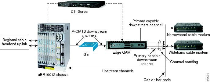
The DS channels are used either as primary channels (used for both broadband and narrowband channels) or secondary channels (used only for wideband channels), or both. The solution provides narrowband data services to support DOCSIS 1.x or 2.0 modems and wideband data services to support DOCSIS 3.0 modems over existing HFC networks and allows DOCSIS 1.x or 2.0 and DOCSIS 3.0 modems to share the same DS channel.
A maximum of eight channel bonding groups are supported.
The Cisco wideband CMTS uses one or more external edge QAM (EQAM) devices. The EQAM device is a network element in a separate chassis from the CMTS. The EQAM device has two or more Gigabit Ethernet input interfaces that connect to a wideband shared port adapters (SPA). For output, the EQAM device has multiple QAM modulators and RF converters that connect to an HFC network. The EQAM device accepts MPEG over IP on its Gigabit Ethernet interfaces and routes the services to its QAM RF outputs.
The enhanced Cisco Service Control solution leverages the SCE bandwidth control and reporting capabilities to monitor and control the CMTS resources at the QAM level. Multiple QAMs are aggregated into a virtual group (bundle group). The bandwidth allocation for different modems are done both on the CMTS and the EQAM. The EQAM minimizes the packets waiting in queue for each channel.
The EQAM manages the queues differently for legacy and 3.0 modems:
•![]() All traffic to the legacy modems are routed through the primary narrowband channel queue.
All traffic to the legacy modems are routed through the primary narrowband channel queue.
•![]() Traffic to 3.0 modems are routed through the shortest possible queue.
Traffic to 3.0 modems are routed through the shortest possible queue.
This feature is supported on Cisco uBR-MC3GX60V Broadband Processing Engine (BPE). The Cisco uBR-MC3GX60V Broadband Processing Engine (BPE) is a high-capacity, DOCSIS 3.0-capable line card for the Cisco uBR10012 Universal Broadband Router. Each line card supports 72 DOCSIS downstream and 60 upstream channels. For details about the line card, see the product datasheet on Cisco.com at the URL http://www.cisco.com/en/US/prod/collateral/modules/ps4969/ps11291/data_sheet_c78-642540.html
Bandwidth Control Enhancements
The enhancements to the SCE bandwidth control include:
•![]() Support for wideband channels—A two-level virtual link hierarchy is created to support the wideband channels. The wideband channels are associated with the Aggregate Global Control (AGC) that provides a constant output signal despite variations in input signal strength. Wideband channels are associated with three AGCs in a two-level hierarchy.The top-level AGC is dynamic and the lower-level AGCs are equivalent to the existing AGCs. At the lower level, all the 3.0 modems for wideband are aggregated into one AGC. The other AGC contains both legacy and 3.0 modems.
Support for wideband channels—A two-level virtual link hierarchy is created to support the wideband channels. The wideband channels are associated with the Aggregate Global Control (AGC) that provides a constant output signal despite variations in input signal strength. Wideband channels are associated with three AGCs in a two-level hierarchy.The top-level AGC is dynamic and the lower-level AGCs are equivalent to the existing AGCs. At the lower level, all the 3.0 modems for wideband are aggregated into one AGC. The other AGC contains both legacy and 3.0 modems.
The committed information rate (CIR) and peak information rate (PIR) parameters are derived from the CMTS and QAM configurations.
For the example, consider a wideband channel that includes three channels. One of the three channels is a primary channel (narrowband) and contains a mix of legacy and 3.0 cable modems. If 20 percentage bandwidth of the narrowband channel is allocated to 3.0 cable modems, the CIR and PIR values are calculated as:
Each QAM rate - X = 30 Mb
Percentage bandwidth allocated for 3.0 cable modems = 20 percentage
Note ![]() For Arris CMTS, SCE does not support bandwidth percentage share for DOCSIS 3.0 cable modem.
For Arris CMTS, SCE does not support bandwidth percentage share for DOCSIS 3.0 cable modem.
Table 2-1 lists the CIR and PIR values of the 3.0 cable modems with 20 percentage bandwidth of narrowband channel allocation.
|
|
|
|
|---|---|---|
Wideband-Cable1/0/0:0 (top level) |
0 |
90 Mb (3X) |
Wideband-Cable1/0/0:0_P |
24 Mb (0.8X) |
30 Mb (X) |
Wideband-Cable1/0/0:0 _W |
20 |
90 Mb (3X) |
•![]() Subscriber fairness within virtual links—To enforce subscriber fairness within the virtual links, the bandwidth is first allocated between the subscribers based on their RP level, followed by the services of each subscriber.
Subscriber fairness within virtual links—To enforce subscriber fairness within the virtual links, the bandwidth is first allocated between the subscribers based on their RP level, followed by the services of each subscriber.
•![]() Application limitation within virtual links—SCE limits specific applications within the virtual link without losing control over the traffic.
Application limitation within virtual links—SCE limits specific applications within the virtual link without losing control over the traffic.
•![]() Enabling global control with CMTS-awareness solution.
Enabling global control with CMTS-awareness solution.
Upstream Bonding of Multiple Channels
CMTS supports upstream channel bonding to provide higher bandwidth for the cable modems in the upstream direction.
The Upstream channel bonding is similar to the downstream channel bonding explained earlier. However, the Upstream VLINK to channel mapping considers only the total bandwidth available from the configured channels for PIR and CIR computation.
A maximum of eight channel bonding groups are supported.
Upstream Logical Channels
The concept of a logical channel refers to the time-division multiplexing (TDM) of the same radio frequency (RF) spectrum allocated to one physical upstream port. All logical upstream channels defined within a physical upstream port share the same upstream RF spectrum or the bandwidth.
Using the Logical Channel Support feature, cable system operators can segment and time-multiplex one spectrum for supporting the legacy modems, near and far modems, and new DOCSIS 3.0 modems with various service levels.
CMTS supports upstream logical channels for better bandwidth management. The bandwidth of the physical channel is divided between logical channels. But, the bandwidth of one logical channel is always equal to the bandwidth of the physical channel.
In the following example, the MAC domain have five upstream channels, each split into two logical channels. The domain also has tow bonding groups and the logical channels are grouped.
CMTS: 10.52.206.2
Mac Domain - Cable 5/0/0 (ifIndex 1780)
US 0 (BW: 2000)
US 0.0 (BW 2000) (ChId 13)
US 0.1 (BW 500) (ChId 14)
US 1 (BW: 1500)
US 1.0 (BW 1500) (ChId 15)
US 1.1 (BW 1000) (ChId 16)
US 2 (BW 2500)
US 2.0 (BW 2500) (ChId 17)
US 2.1 (BW 1500) (ChId 18)
US 3 (BW 3000)
US 3.0 (BW 3000) (ChId 19)
US 3.1 (BW 500) (ChId 20)
US 4 (BW 2500)
US 4.0 (BW 2500) (ChId 21)
US 4.1 (BW 1000) (ChId 22)
BG -131 : 13, 15, 18, 22
BG -132 : 14, 16, 18, 21
In this example, upstream channel 3 (US 3) is not part of any bonding group and the channel is not overlapped. Channel 18 is overlapped in bonding group 131 and 132.
Example of VLINK configuration for this upstream logical channel configuration:
virtual index=1, name=codc_Cable5/0/0-US3, pir= 3000, cir=16, al=5, dynamic agc index=1
channel index=1, name=codc_Cable5/0/0-US3, pir=3000, cir=16, al=5, agc index=1
virtual index=2, name=codc_Cable5/0/0-US, pir= 8500 (2000+1500+2500+2500) , cir=16, al=5,
dynamic agc index=2
channel index=3, name=codc_Cable5/0/0-US0, pir=2000, cir=16, al=5, agc index=3
channel index=4, name=codc_Cable5/0/0-US1, pir=1500, cir=16, al=5, agc index=4
channel index=5, name=codc_Cable5/0/0-US2, pir=2500, cir=16, al=5, agc index=5
channel index=6, name=codc_Cable5/0/0-US4, pir=2500, cir=16, al=5, agc index=6
channel index=7, name=codc_Cable5/0/0-BG-131, pir=6000  (2000+1500+1500+1000), cir=16,
al=5, agc index=7
channel index=8, name=codc_Cable5/0/0-BG-132, pir=5500  (500+1000+1500+2500), cir=16,
al=5, agc index=8
This is the mapping table for this upstream logical channel configuration:
10.52.206.2_1780_13=3
10.52.206.2_1780_14=3
10.52.206.2_1780_15=4
10.52.206.2_1780_16=4
10.52.206.2_1780_17=5
10.52.206.2_1780_18=5
10.52.206.2_1780_19=1
10.52.206.2_1780_20=1
10.52.206.2_1780_21=6
10.52.206.2_1780_22=6
10.52.206.2_1780_13151822=7
10.52.206.2_1780_14161821=8
Overlapped Bonding Groups
In Overlapped Bonding Groups, a single channel can be part of more than one bonding group.
If channels are overlapped across the bonding groups, the SCE models those bonding groups under the same VLINK. If the channels are not overlapped, then the SCE models those bonding groups as separate VLINK.
The computation of the PIR and the CIR values for the VLINK and Channels are done by retrieving the percentage of channel BW allocated to DOCSIS 3.0 traffic that are part of overlapped bonding groups and also the percentage that is allocated to DOCSIS 2.0 traffic from those channels.
Note ![]() Channels and Bonding Groups that are overlapped across MAC domains are not supported.
Channels and Bonding Groups that are overlapped across MAC domains are not supported.
Example:
In this example, taken from the SNMP output, the Downstream bonding group and the overlapped bonding groups are shown. There are 4 bonding groups—the first two are mapped to 5/0/0 and another two are mapped to 6/0/0. Channel 2 and 3 are overlapped.
Cable5/0/0-downstream
35: ifDescr(2).1121 (octet string) Wideband-Cable1/0/0:0
Modular-Cable1/0/0:0
Modular-Cable1/0/0:2
Modular-Cable1/0/0:3
36: ifDescr(2).1122 (octet string) Wideband-Cable1/0/0:1
Modular-Cable1/0/0:1
Modular-Cable1/0/0:2
Modular-Cable1/0/0:3
Cable6/0/0-downstream
37: ifDescr(2).1123 (octet string) Wideband-Cable1/0/0:2
Modular-Cable1/0/0:4
38: ifDescr(2).1124 (octet string) Wideband-Cable1/0/0:3
Modular-Cable1/0/0:5
These are the list of channels and radio frequency bandwidth allocation for each channel on each wideband interface:
1121.1005.0 (gauge) 25 (25% of ifSpeed 4750) 6650
1121.1005.2 (gauge) 50 (50% of ifSpeed 9500) 13300
1121.1005.3 (gauge) 20 (20% of ifSpeed 3800) 5320
1122.1005.1 (gauge) 50 (50% of ifSpeed 9500) 13300
1122.1005.2 (gauge) 50 (50% of ifSpeed 9500) 13300
1122.1005.3 (gauge) 20 (20% of ifSpeed 3800) 5320
1123.1005.4 (gauge) 25
1124.1005.5 (gauge) 50
The following example provides details of the logic for IPDR and DHCP mapping:
- virtual index=1, name=Cable5/0/0-downstream, pir= 76000 , cir=16, al=5, dynamic agc
index=1
- channel index=1, name=Cable5/0/0-downstream-L0, pir=19000, cir=14250, al=5, agc index=2
- channel index=2, name=Cable5/0/0-downstream-L1, pir=19000, cir=9500, al=5, agc index=3
- channel index=3, name=Cable5/0/0-downstream-L2, pir=19000, cir=16, al=5, agc index=4
- channel index=4, name=Cable5/0/0-downstream-L3, pir=19000, cir=11400, al=5, agc index=5
- channel index=8, name=Cable5/0/0-downstream-W0, pir=57000, cir=18050, al=5, agc index=9
- channel index=9, name=Cable5/0/0-downstream-W1, pir=57000, cir=22800, al=5, agc index=10
- channel index=7, name=Cable5/0/0-downstream-W, pir=76000, cir=40850, al=5, agc index=8
Bonding Groups with Multiple Primary Channels
To support backward compatibility, the individual channels in the bonding groups can be used in parallel by legacy cable modems that work in earlier versions of DOCSIS. In this mode, there is a mix of legacy cable modems and DOCSIS 3.0 cable modems working on the same channels.
Primary channels of a CMTS are those channels that are capable of supporting legacy or DOCSIS 2.0 modems.
Channels that are configured to support legacy or DOCSIS2.0 cable modems must be configured as Primary Channel. Also, each bonding group must include at least one channel that is defined as a Primary Channel.
The basic SCE - CMTS integration supports only a single Primary channel for each bonding group. The basic integration supports a mix of DOCSIS 2.0 and DOCSIS 3.0 cable modems on the primary channel but it is limited to single channel on each bonding group. The main reason for the single primary limitation is the DHCP protocol. The SCE - CMTS integration contains SNMP polling to get the CMTS configuration and DHCP sniffing for mapping of cable modem to virtual link inside the SCE. The CMTSs report, through the DHCP protocol, about single Primary channel only.
With the IPDR LEG, SCE supports multiple primary channels. The IPDR records includes the required information for mapping cable modems and CPEs to virtual links. A maximum of eight channels bonded (BG with 8 channels) are supported.
The SCE supports bonding groups by creation of virtual-links hierarchy. Figure 2- describes the SCE configuration to support bonding groups. The bonding group is associated with aggregate global controller (AGC) in the top level. Under the top-level AGC, there is one AGC that aggregates all the DOCSIS 3.0 cable modems in the bonding group, and another AGC for the DOCSIS 2.0 cable modems. From release 3.7.0, if there are more than one primary channel in the bonding group, a legacy AGC is created for each primary channel. For example, in Figure 2-2 there are two primary channels and two corresponding legacy AGCs.
Figure 2-2 Bonding Group With Two Primary Channels
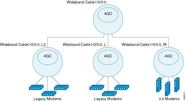
In a multiple primary channels s scenario, the specific mapping is required only for the DOCSIS 2.0 cable modems since they are limited to the specific physical channel. DOCSIS 3.0 cable modems can generate traffic over all channels.
The exact primary channel can be identified by the IPDR messages. In this example, 13 is the downstream channel index and 3 is the upstream channel index.
<CmMacAddr>MAC-ADD:00-00-00-18-9b-8d-fc-cd</CmMacAddr>
<CmIpv4Addr>IP_V4:10.12.150.138</CmIpv4Addr>
<CmtsMdIfName>'Cable6/0/0'</CmtsMdIfName>
<CmtsMdIfIndex>1031</CmtsMdIfIndex>
<CmtsRcsId>13</CmtsRcsId>
<CmtsTcsId>3</CmtsTcsId>
Dynamic Channel Change of Cable Modem
For load balancing the cable modems on the available interfaces, a CMTS can dynamically change the channels assigned to a cable modem. During a dynamic channel change, a cable modem does not process a new DHCP login process.
Note ![]() Dynamic Channel Change using the dcc command does not work in versions earlier than Cisco IOS Release 12.2S.
Dynamic Channel Change using the dcc command does not work in versions earlier than Cisco IOS Release 12.2S.
If enabled, SCE uses IPDR LEG to identify the channel changes.
IPDR messages are generated by CMTS for each cable modem when the modem gets associated with different channels on the CMTS. This IPDR message includes information on the channel assigned to the cable modem. The VLM monitors the channels and updates the cable modem to virtual link mapping when a channel changes.
IPDR LEG registers CM Registration and DOCSIS Type templates and looks for the corresponding IPDR messages from the CM-STATUS and SAMIS TYPE-1 type templates.
This is an example of the IPDR message:
<CmMacAddr>00-00-00-18-9b-8d-fc-cd</CmMacAddr>
<CmIpv4Addr>IP_V4:10.12.150.138</CmIpv4Addr>
<CmtsMdIfName>'Cable6/0/0'</CmtsMdIfName>
<CmtsMdIfIndex>1031</CmtsMdIfIndex>
<CmtsRcsId>53</CmtsRcsId>
<CmtsTcsId>3</CmtsTcsId>
<CMTSupIfName>'Ca7/0/0-upstream1'</CMTSupIfName>
<CMTSdownIfName>'Ca7/0/0-downstream'</CMTSdownIfName>
In the above example 53 is the downstream channel index and 3 is the upstream channel index in which the cable modem (00-00-00-18-9b-8d-fc-cd) is associated with the CMTS.
The CMTS sends IPDR messages for each cable modem association and channel changes to the collector. The IPDR LEG gets the mapping of the latest channel changes and updates the SCE.
Support for Non-Cisco CMTS
Starting from SCE 3.7.0, Cisco SCE supports integration of non-Cisco CMTSs in an SCE-CMTS integration scenario. For the integration, SCE uses the IPDR LEG.
The structure of the DHCP messages varies between various CMTS vendors, but the IPDR records or messages are defined as part of the DOCSIS standard and are identical over all the vendors.
For non-Cisco CMTS, The VLM supports SNMP polling to get the CMTS configuration from these CMTS.
Mapping of Cable Modems Through DHCP Sniffing
The narrowband channels are updated in the IfIndex in option 82, where the IfIndex is used for both legacy and 3.0 modems. In SCE, wideband channels are associated with three AGCs in a two-level hierarchy and the mapping of the modems to appropriate AGCs depends on these factors:
•![]() In the VLM mapping table, the modems are mapped from the narrowband IfIndex to the wideband group.
In the VLM mapping table, the modems are mapped from the narrowband IfIndex to the wideband group.
•![]() Modems are linked to the appropriate AGC based on their type.
Modems are linked to the appropriate AGC based on their type.
Detecting 3.0 Modems
The legacy and 3.0 modems are distinguished based on the information in the bootfile. The operators use the bootfile name to identify the modem type and the service package for the subscriber. The service packages are used to map the modems to the right VLM.
The bootfile name is configured using these options:
•![]() Option 67 in DHCP is called the Bootfile name, the information configured in this field is extracted and sent to the DHCP sniffer.
Option 67 in DHCP is called the Bootfile name, the information configured in this field is extracted and sent to the DHCP sniffer.
•![]() DHCP header contains a field called Bootfile name in the DHCP header.
DHCP header contains a field called Bootfile name in the DHCP header.
DHCP login event generator (LEG) includes regular expression capabilities that are used to configure specific information in the Bootfile name, which is used for mapping.
The VLM extracts the DHCP sniffer query results indicating the modem type (legacy or 3.0). Based on the DHCP sniffer output, VLM maps the modems to either primary or secondary channels.
Mapping of Cable Modems Through Internet Protocol Details Report (IPDR) Streaming Protocol
Whenever a legacy modem registers with a CMTS, the modem sends a CM REG TYPE IPDR message which contains CmtsTcsId and CmtsRcsId. These IDs are used for upstream and downstream index mapping.
For a DOCSIS 3.0 modem, mappings are updated on receiving a periodic SAMIS TYPE1 message from the CMTS for a modem. The value of ServiceFlowChSet in the message is used for mapping the upstream and downstream indices.
Detecting 3.0 Modems
The value of ServiceFlowChSet in the SAMIS TYPE1 message is used to detect a DOCSIS 3.0 modem. If the value is greater than 255, then it is a DOCSIS 3.0 modem; else it is a legacy modem.
 Feedback