Table Of Contents
Initialization and Self-Test Problems
Troubleshooting
This chapter provides basic installation troubleshooting information. The chapter includes the following sections:
•Initialization and Self-Test Problems
Note This chapter provides only hardware troubleshooting information that does not require access to the router's command-line interface (CLI) or knowledge of CLI commands. For more advanced troubleshooting, refer to the Cisco IOS online document Troubleshooting Tips for the Cisco uBR924 Cable Access Router.
Troubleshooting Overview
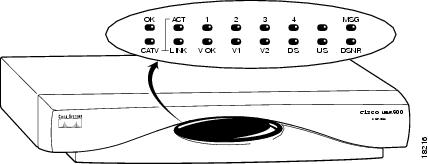
Installation problems with Cisco uBR924 routers are commonly due to the cable system and its topography. LEDs on the front panel of the Cisco uBR924 router reveal operational status and help you determine problem areas. See Figure 4-1 for the layout of the LEDs on the router's front panel; see Table 1-1 for a description of these LEDs.
Figure 4-1 Cisco uBR924 Cable Access Router Front Panel LEDs
Initialization and Self-Test Problems
When the Cisco uBR924 router first powers on, the following occurs:
1. The router runs its self-test and diagnostic procedures. All LEDs (except for the four Ethernet LEDs and the ACT LED) briefly light and then turn off when self-test and diagnostic procedures are successful. The procedures ensure Cisco uBR924 components are functioning. To complete all self-test and diagnostic procedures, the Cisco uBR924 processor must be able to:
–Perform a system reset trap.
–Fetch and execute instructions from the ROM Monitor area of the bootflash chip.
–Write several internal registers and reset the control program without crashing.
–Correctly configure the port A and port D registers.
–Perform conditional branches.
–Ensure all software-controlled LEDs are functional.
2. The next step of the self-test is to initialize the memory controller and its Dynamic Random Access Memory (DRAM). If a failure exists, the OK LED turns off and the following LEDs on the bottom row turn on to indicate the specific problem that occurred.
–The router first attempts to initialize the memory controller. If this fails, the DS and DSNR LEDs light and remain on to indicate a problem with the memory controller. Otherwise, the console port is initialized and the banner is output to the console port.
–Next, the router performs a self-test on the low registers of the DRAM. If a problem exists, the V2, the DS, and the DSNR LEDs light and remain on to indicate a processor cache failure.
–If the cache memory passed the self-test, the next portion of DRAM is tested. If this self-test fails, the V-OK, V2, DS, and DSNR LEDs light and remain on to indicate a memory or controller problem.
–The router then attempts to clear the BSS area of the DRAM; if this fails, the V2, DS, and US LEDs light and remain on to indicate a memory or controller problem.
–Finally, the router attempts to clear the rest of DRAM. If this fails, the DS LED lights and remains on, while all other LEDs remain off to indicate a possible memory or controller problem.
Table 4-1 summarizes the self-test failure codes displayed by the LEDs; these patterns appear only when the OK LED turns OFF and remains OFF during boot.
If the main initialization routine successfully completes, all LEDs turn off.
3. If all self-tests passed, the router boots the Cisco IOS image stored in its NVRAM memory. The OK (power) LED blinks during the boot process and remains on if the router was able to successfully load and start up the image. If the LED does not start to blink, proceed to the "Power Subsystem" troubleshooting section.
4. The router starts normal operations after it starts up the Cisco IOS image. At this point, the US, DSNR and LINK LEDs remain on to indicate the router is operational and receiving a healthy signal:
–The DS LED indicates the router is locked to a downstream channel.
–The US LED indicates the router has established connectivity with the CMTS and is operating within 6 dB of desired power level (generally within 3 dB).
–The LINK LED indicates the cable interface is operational.
–The DSNR LED reveals the router is receiving a quality downstream signal with a low signal-to-noise ratio (SNR) and that is 5 dB above the downstream lock threshold.
–The ACT LED blinks to indicate activity on the cable interface.
–The Ethernet 1, 2, 3, 4 LEDs blink to indicate activity from the PCs and other customer premises devices connected to the corresponding Ethernet ports.
–The V OK LED indicates the VoIP system is operational. The V1 and V2 LEDs light when the voice ports are active. (These LEDs light only if the router has loaded a Cisco IOS image with voice support).
Note Because the signal-to-noise ratio and lock threshold can drift, they are regularly checked and the DSNR LED is updated. While this might cause the DSNR LED to occasionally blink briefly, under normal conditions the DSNR LED should remain on.
5. When the router and computer have booted successfully, you should be able to access an Internet web site, which will confirm that the router is configured correctly. If you cannot access a web site, proceed to the "PC Subsystem" section.
6. The voice port LEDs (V1 and V2) on the cable access router light when a subscriber establishes a VoIP connection. If you do not have dial tone on the Cisco uBR924 voice ports and cannot establish a VoIP connection, proceed to the troubleshooting "VoIP Subsystem" section.
Troubleshooting Subsystems
The key to troubleshooting is to isolate a problem to a specific subsystem:
•Power subsystem
•Coaxial cable subsystem
•RF and digital signal subsystem
•PC subsystem
•VoIP subsystem
Figure 4-2 on the next page provides a general troubleshooting flowchart. Table 4-2 and Table 4-3 help you correlate LED behavior with possible problems, and suggested courses of actions.
Figure 4-2 Basic Troubleshooting Strategy for Startup Problems
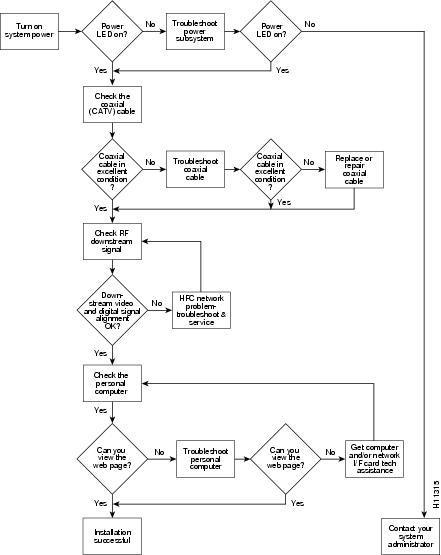
Table 4-2 General Troubleshooting Tips
LED Status Possible Problem Suggested ActionOK
System status LED is off.
Power cord not properly seated.
Power outlet not operating.
Power supply has failed.
The router failed its self-test.Check power connections.
Check the outlet.
Contact field service dispatch to replace the power supply.
See Table 4-1 or contact field service dispatch to replace the unit.1, 2, 3, or 4
Ethernet LEDs are off when data is transmitted to/from the device.
PC/device not powered on.
Bad Ethernet connection.
Incorrect cable between the router, the hub if applicable and the PC.
Faulty Ethernet card.Verify the PC/device is powered on.
Reseat the Ethernet cable at both ends. Make sure TCP/IP and DHCP are enabled.
Replace the cable, reviewing the hub user guide or Ethernet user guide.
Notify the subscriber to replace the Ethernet card.LINK
Cable RF LED is off.
Cable RF LED is blinking.Router searching for a signal; RF levels wrong.
Cable is out.
Router is locked to a signal and connecting to the headend per DOCSIS.Check for a DOCSIS system signal and verify the nearby analog video signal is within the correct range—0 to +15 dBmV for most CATV systems.
Check if the cable TV is working if the subscriber also subscribes to broadcast TV services.
Wait until the router completes initialization. The router can pause on a digital video signal during installation, but will timeout and then locate the DOCSIS system signal.DS
Downstream LED is off.
RF coaxial cable is not properly connected to the router.
Reconnect the cable.
US
Upstream LED is off.
Upstream signal is not reaching the headend; router is unable to communicate with the remote end. Systematic RF noise problem or other outage.
Verify continuity back to the headend using the standard procedures for your system. Temporarily locate the router closer to the ground block, the tap, or another tap closer to the headend— ensuring correct RF input level at all times.
DSNR
Downstream signal-to-noise LED is off.
Systematic RF noise problem or other outage.
Verify correct RF input to the router. Temporarily locate the router closer to the ground block, the tap, or another tap closer to the headend—ensuring correct RF input level at all times.
Do not install the router unless your system management expressly states this is the procedure to follow. This is an early indication of low quality cable signals and indicates a high likelihood of intermittent router operation.
Power Subsystem
To help isolate a problem with the Cisco uBR924 router power subsystem, look at the OK LED. Does the LED remain on when self-test is completed and a software image booted?
•If yes, the power source is good and the power supply is functional.
•If no, make sure the power cable is connected at the back of the router and that the power supply is properly connected to power at the wall outlet.
–If the OK LED remains off but other LEDs are ON, check Table 4-1 for possible diagnostic codes.
–If the OK LED remains off and all other LEDs are also OFF, check the power source or power supply. Connect the power cord to another power source, if available. If the LED goes on, the problem is the first power source.
–If the OK LED fails to blink after you connect the power cord to a new power source, the power supply is probably faulty.
Note If you are unable to resolve the problem or you determine that either a power supply or cable access router connector is faulty, contact your field office for instructions.
Coaxial Cable Subsystem
For proper operation the Cisco uBR924 router must be able to establish a connection with the service provider's CMTS. There are many conditions inherent to coaxial cable that can inhibit this connection:
Step 1 Verify the cable connection from the router to the HFC plant and headend by checking the video reception. You should test the same coaxial cable that the router is connected to—if necessary, disconnect the router from the coaxial cable and connect a cable-ready TV in its place.
If the TV does not receive any cable channels, contact the service provider to re-establish service to the site. If the TV does receive cable channels, it indicates that the basic infrastructure between the site and the HFC plant and headend is working; however, because data connections are much more sensitive to signal interference than cable TV service, it is still possible that a problem exists that prevents reception of the data signals.
Step 2 If you are using a splitter or couple to share the coaxial cable between a TV and the router, remove the splitter/coupler, TV, and any other devices connected to the cable (such as video or DVD players) so that the router connects directly to the coaxial cable coming out of the CATV wall outlet. Make sure the router is the only device on this segment of cable.
If the router functions in this configuration, inspect the splitter and any other devices that were installed on this cable segment. If necessary, upgrade them and their interconnecting cables with ones that have higher-quality connectors—see "Coaxial Connector and Cable Specifications" in "Connector and Cable Specifications" for the recommended cable and connector quality. A high-pass filter might be necessary between the modem and TV to prevent signal interference. If this does not help, you might need to install a separate cable for TV reception.
Step 3 Disconnect the coaxial cable from the back of the router and inspect the cable and its connector. Is the center conductor on the coaxial cable end straight and of the correct length to ensure a good connection?
If the center conductor is not straight or appears to be too long or too short, cut the coaxial cable behind the connector end, and strip the insulation back. Make sure that the newly exposed center conductor is straight. Before replacing the new cable connector end, check the general condition of the cable. Make sure the new conductor end is securely crimped to the cable.
Note The center connector should extend 1/8 inch (3.2 mm) beyond the end of the connector.
Step 4 Is the coaxial cable running to the router in excellent condition?
The coaxial cable between the router and the cable tap must be very high quality. The cable insulation must be at least 80% braid with foil. If the existing cable appears to be of lesser quality or in poor condition, replace the cable from the ground block or tap to the cable end.
Step 5 Is the coaxial cable connection to the back of the cable access router secure?
Check that the coaxial cable end is securely screwed onto the F-connector at the back of the cable access router. Hand-tighten the connector, making sure it is finger tight; then give it a 1/6 turn.
Note If you are unable to resolve the problem, contact your internal service organization for instructions and assistance.
RF and Digital Subsystem
The use of RF and digital signals on the same cable can lead to interference if the HFC network is not correctly configured.
Step 1 Is the downstream video signal being received at the ground block or at the tap?
Connect a premium services cable converter to the ground block or at the tap and contact field service dispatch. Ask the CMTS system administrator to check if they can locate the box on the network by sending an impulse, or on-demand, video signal to the converter.
If field service can locate the converter at the ground block or at the tap, repeat the test with the cable access router connected to the cable end near the computer.
If field service cannot locate the converter at the cable end, but can locate the converter at the ground block or tap, replace the cable from the ground block or tap to the cable end.
Step 2 Check the adjacent video channel. The digital data signal should be approximately in the range of -2 to +15 dBmV on a nearby analog channel. Confirm this value using a portable field strength meter, or power meter, to measure the adjacent analog video signal.
PC Subsystem
To isolate a problem with a PC that is connected to the Cisco uBR924 router:
Step 1 Can you access a web page using the web browser installed on the computer?
If you cannot access a web page, verify that the computer network protocol is configured for TCP/IP and that DHCP services are enabled using the following Windows 95 options:
a. Turn on your PC and enter your network username and password.
b. Choose Start:Settings:Control Panel to display the Control Panel.
c. Double-click the Network icon. The Network window appears with the Configuration tab in the foreground. If the Configuration tab is not in the foreground, click this tab.
d. Scroll the network components list box until the Ethernet adapter TCP/IP option displays for your network adapter and double-click the selection. The TCP/IP Properties window appears with the IP Address tab in the foreground. If the IP Address tab is not in the foreground, click this tab.
Note If there is no TCP/IP entry for the installed network adapter, the computer is not configured for IP. Refer to the subscriber's computer and network interface card user guides on how to configure these settings.
e. Make sure that the button next to Obtain an IP address automatically is selected. If this button is not selected, the computer is not configured for DHCP. Select the Obtain an IP address automatically radio button now and save the configuration settings.
f. Close all networking windows and close the Control Panel.
g. Follow the onscreen instructions and reboot your PC.
Step 2 Is the network interface card operational?
Verify that the network card is installed properly and that necessary software drivers have been installed and are running on the computer. Consult the user guide or other documentation that accompanied the network card. Contact technical support for the network card manufacturer as necessary.
Step 3 Is the computer preconfigured to work with special software such as America Online? Some computers come with dialup adapters preconfigured to work with special software. To ensure the setup is correct, follow the procedures below.
Setting the Internet Properties
a. Turn on your PC and enter your network username and password.
b. Choose Start:Settings:Control Panel to display the Control Panel.
c. Double-click the Internet icon. The Internet Properties window appears with the General tab in the foreground.
d. Click the Connection tab. The Internet Properties Connection tab displays. The Connect to the Internet: as needed check box is checked and the name of the dialup adapter appears in the Dial-Up Networking connection list box.
e. Click the Connect to the Internet: as needed check box to deselect the option.
Note The check box must not be checked. If the checkbox is checked, the computer attempts to open a dialup adapter connection each time a network application is started.
f. Click OK.
g. From the Control Panel, double-click the System icon. The System Properties window displays with the General tab in the foreground.
h. Click the Device Manager tab.
i. Click the Network adapter selection. Make sure the display does not contain either a red "X" or a yellow exclamation point.
j. Click OK.
Setting Network Components
a. Turn on your PC and enter your network user name and password.
b. Choose Start:Settings:Control Panel to display the Control Panel.
c. Double-click the Network icon. The Network window appears with the Configuration tab in the foreground.
d. Scroll the list box until the particular dialup adapter selection appears. If the computer has America Online installed, two network components will be displayed: AOL Dialup Adapter and TCP/IP:AOL Dialup Adapter.
Note The computer might have more than one dialup adapter. Be sure to select the right dialup adapter.
e. If the subscriber does not intend to use America Online, remove both these components from the Network components list box:
•Click AOL Dialup Adapter to highlight it. Click Remove.
•Click TCP/IP:AOL Dialup Adapter to highlight it. Click Remove.
f. If the subscriber intends to use America Online, double-click the TCP/IP component associated with the dialup adapter. The TCP/IP Properties window appears with the IP Address tab in the foreground.
g. Click the Obtain an IP address automatically button. The IP address for the dialup connection will only be assigned when the connection is made. By default, the computer will be assigned an IP address by the Cisco uBR924 router via DHCP.
Note When set up correctly, the Cisco uBR924 router is the default Internet connection device. The subscriber might select the dialup adapter as an alternative connection path.
h. Click OK. A dialog box appears, informing you for the change to become effective, the computer must be rebooted.
i. Click Yes to reboot the computer.
VoIP Subsystem
If you do not have dial tone when picking up a telephone or fax device connected to the Cisco uBR924 router's voice ports, ensure the router is using a Cisco IOS image that supports voice. For more information on Cisco IOS images, refer to the release notes that accompanied the router; also refer to the Cisco uBR924 Cable Access Router Software Configuration Guide.
Table 4-3 gives some general VoIP troubleshooting tips.
Using the Reset Switch
The Cisco uBR924 router contains a reset switch with three different actions:
•A quick press (less than 10 seconds) initiates a hardware reset, similar to a power cycle or software reload.
•Pressing the reset switch from between 10 and 30 seconds causes the router to clear its saved RF parameters and do a hardware reload. This reload is similar to plugging in the router for the first time.
•Pressing the reset switch for longer than 30 seconds causes the router to erase its system image and download a new system image over the cable interface should the CMTS system administrator have set certain options in the configuration file, in conjunction with field service personnel. The router then reboots with this new image.
See Table 4-4 for additional elaboration.
Note The reset switch on the back panel of the Cisco uBR924 cable access router is recessed to prevent accidental resets of the router. To depress the switch, use a blunt object, such as a pen or pencil point; do not use a sharp object, such as a knife or awl, because this could permanently damage the switch and the router's circuitry.
Further Contacts
If you experience trouble with the startup that is not resolved with the procedures and tips in this chapter, contact field service dispatch for further assistance and instructions. Also see the documentation available in the Broadband Cable section on CCO and the Documentation CD-ROM.
Note Cisco recommends that a CMTS systems engineer or network administrator be available, or on-call, to assist field service technicians or installers in troubleshooting a Cisco uBR924 cable access router.
If you are a network administrator or systems engineer with a Cisco product covered under warranty or a maintenance contract, contact Cisco's Technical Assistance Center (TAC) at 800 553-2447, 408 526-7209, or tac@cisco.com.