Chapter 1 - Product Overview
Available Languages
Table Of Contents
Cisco uBR924 Cable Access Router Description
Initial Power-On and Provisioning
Backup POTS Connection (RJ-11 Line Connector)
Product Overview
This chapter describes the Cisco uBR924 cable access router and its interaction with the Cable Modem Termination System (CMTS)—the cable system headend equipment that provides Internet (TCP/IP) connectivity for subscribers over the cable broadband infrastructure. The chapter provides physical and functional overviews of the Cisco uBR924 cable access router and its supported operating modes.
Cisco uBR924 Cable Access Router Description
This section provides an overview of the Cisco uBR924 cable access router, its hardware, and its basic operation:
•
Initial Power-On and Provisioning
Introduction
The Cisco uBR924 cable access router functions at its most basic level as a cable modem—a modulator/demodulator that provides high-speed network access on the cable television system to residential and small office/home office (SOHO) subscribers. The router is based on the Data-Over-Cable Service Interface Specifications (DOCSIS), a standard developed with service providers to ensure that any DOCSIS-certified cable modem can interoperate with any bidirectional, DOCSIS-qualified CMTS.

Note
In addition to providing DOCSIS connectivity, the Cisco uBR924 router can optionally provide advanced data and routing features, as well as telephone and fax services. The Cisco uBR924 router uses the cable system's existing physical plant to provide Internet and other wide area network (WAN) connectivity over the service provider's Hybrid/Fiber Coax (HFC) cable system.
The router can connect one or more computers to the Internet over the HFC cable system. Depending on the other services purchased from the service provider, subscribers can also send voice and fax traffic over the cable system, or they can use the cable system to link multiple sites into a secure private company network (Intranet). Subscribers can use the Cisco uBR924 router to create high-speed, permanent access to the Internet, without the need for telco-based services such as leased lines.
Routing and Bridging
When acting as a DOCSIS-compliant cable modem, the Cisco uBR924 router provides DOCSIS bridging for one or more PCs and other customer premises equipment (CPE). The router ships from the factory with a Cisco IOS software image stored in nonvolatile Flash memory that supports DOCSIS-compliant bridging data operations.
Based on the feature licenses your company purchased, other Cisco IOS images can be downloaded from Cisco Connection Online (CCO). These images provide additional functionality such as advanced routing capabilities, advanced security, and Voice over IP (VoIP) support.
For most residential applications that involve basic Internet access or VoIP services, the Cisco uBR924 router is configured as a bridge. For residential and SOHO applications that involve special feature sets such as the firewall features, or that include connection to an existing network at the site, the Cisco uBR924 is configured as a router.
Note
The following paragraphs summarize the router's operation in both bridging and routing modes:
•
–
–
–
Regardless of the configuration, Cisco IOS software treats all four Ethernet hub ports as one Ethernet interface. See Figure 1-1 for a typical configuration.
Figure 1-1 Cisco uBR924 in a Bridging Configuration
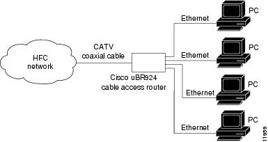
•
Figure 1-2 Cisco uBR924 in a Routing Configuration
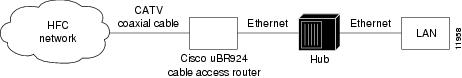
In routing mode, no maximum limitation exists. The Cisco uBR924 is configured to use the IP address of the headend router as the router's default IP gateway.
Note
Upgrading the Software Image
When Cisco IOS images are updated to new releases, the service provider can download them as needed to Cisco uBR924 routers installed in the field (based on the software licenses purchased). See the release notes for the router (listed in "Related Documentation" in the Preface) for a complete list of features and Cisco IOS images that are currently supported.
Service providers can use the router's Media Access Controller (MAC) address to uniquely identify each particular router in the field. The CMTS uses this value to download the proper DOCSIS configuration file to the router before it begins operation.
The DOCSIS configuration file can also contain the name of the software image that the router should be running. If necessary, the CMTS can also download the proper software image to the router and force it to reboot using the new image.
The download of the DOCSIS configuration file usually takes only a few seconds and is done every time the Cisco uBR924 router reboots. The download of the software image can take several minutes to complete, during which time network connectivity is not available. However, the software image must be downloaded only once, until the subscriber needs to be updated with a new or updated image.
The next section, "Initial Power-On and Provisioning," explains this process. See the Cisco uBR924 Cable Access Router Software Configuration Guide for a description on how to download a software image and configuration file to a Cisco uBR924 router installed in the field.
Initial Power-On and Provisioning
The router ships from the Cisco factory ready to work in a DOCSIS-compliant bridging data-only mode. However, before the router can transmit traffic, the CMTS at the headend must properly provision the router as follows:
•
•
•
•
Note
To ensure that subscribers obtain the exact services they have ordered, the Cisco uBR924 router arrives from the Cisco factory with a unique identifier (UID) that consists of a serial number and MAC address. These factory-assigned values are on a label at the bottom of the router; for convenience, these values are also in a barcode label that can be easily scanned for easy entry into the service provider's provisioning and billing system.
Using the MAC address of the router as the key, the CMTS downloads the DOCSIS configuration file and Cisco IOS image that will provide the services that this particular subscriber has purchased. Service technicians at the headend typically create a number of standard configuration files to match the range of services offered by the provider; these configuration files can be created manually or with tools provided by Cisco Systems for this purpose.
The following sections describe the initial power-on and provisioning sequence in more detail, as well as the requirements that must be met by both the router and the CMTS before provisioning can succeed.
Initial Power-On Sequence
When connected and first powered on, the Cisco uBR924 cable access router performs the following DOCSIS-mandated procedure for automatic installation and configuration:
1.
2.
3.
4.
5.
6.
Note
7.
8.
9.
10.

Caution
11.
12.
Note
13.
Note
14.
Alternatively, a system administrator can manually configure the Cisco uBR924 router by giving commands at the router's CLI interface.
15.
Figure 1-3 illustrates the traffic flow during this process.
Figure 1-3 Cisco uBR924 Cable Access Router Provisioning Overview
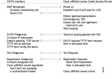
Note
After the Cisco uBR924 router goes online, it sends traffic between the attached CPE devices and the network (Internet, Intranet, VoIP). The service provider typically uses DHCP to assign IP addresses to the CPE devices. The number of IP addresses each subscriber can obtain depends on the services purchased from the provider.
Provisioning Prerequisites
The following requirements must be met before a router can be provisioned:
•
•
•
•
•
Note
•
•
•
–
–
–
Data Operations
This section provides an overview of how data is transmitted to and from the Cisco uBR924 router across the cable system's HFC network. Figure 1-4 illustrates a typical broadband data cable system, showing the network path between the Cisco uBR924 router and the CMTS headend equipment (Cisco uBR7200 series universal broadband router or other DOCSIS-compliant CMTS).
Figure 1-4 Cisco Broadband Data Cable System
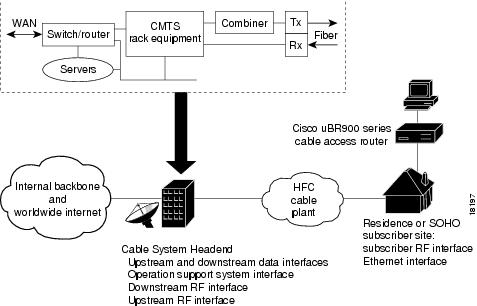
The Cisco uBR924 router provides the connection between the PC and the cable system, modulating the data transmitted to and from the PC so that it can be carried over the coaxial cable installed by the service provider. To avoid interfering with the cable video signals that are also transmitted over this same coaxial cable, the DOCSIS specification allows only certain frequencies to be used for data transmissions. Separate frequencies are used for the data sent from the CMTS to the cable modem (the downstream direction) and for the data sent from the cable modem to the CMTS (the upstream direction).
The CMTS divides the cable plant into downstream channels and upstream segments or clusters of nodes. Each Cisco uBR924 router on the network is configured to receive data on a particular downstream channel. A downstream channel contains one or more upstream segments; partitioning the upstream plant into smaller segments significantly reduces the number of potential ingress sources and failure points.
Downstream Transmissions
Because 90% of the data transmitted on the Internet is, on average, sent from the network to the user, the cable system allocates the majority of bandwidth for downstream data (data sent from the CMTS to the router). Downstream transmissions use a 6 MHz data channel in the 88 to 860 MHz range, providing an approximate maximum bandwidth of 27 or 26 Mbps. This bandwidth is shared among all subscribers who have been assigned to this particular downstream channel.
The CMTS receives the downstream data from its Internet or other WAN connections. It addresses the data to the appropriate Cisco uBR924 router and modulates it for transmission on the cable network. When the data arrives at the subscriber's site, the router modulates it for transmission over the Ethernet connection to the appropriate CPE device.
Upstream Transmissions
The data transmitted in the upstream direction (from the user to the network) is typically much less than that on the downstream direction, so a smaller bandwidth is allocated to it. The upstream transmissions share a 200 kHz-wide to 3.2 MHz-wide channel in the 5 to 42 MHz range, providing a bandwidth of up to 10 Mbps.
Depending on the quality of the physical plant and the CMTS used at the headend, users on a single downstream can be allocated across several upstreams to ensure a responsive network. Service providers can allocate different upstream bandwidths depending on the services purchased by a subscriber. For example, a subscriber purchasing basic home service might be allocated a 128 kbps upstream, while businesses purchasing premium services might be allocated a 384 kbps upstream.
The Cisco uBR924 router receives the upstream data from the CPE devices to which it is connected. It modulates this data for transmission on the coaxial cable system to the CMTS. The CMTS then routes the data to the appropriate destination (local server, Internet, and so forth) through its WAN interfaces.
All DOCSIS cable modems use a request/grant mechanism to obtain bandwidth on the upstream. The CMTS grants the bandwidth according to the requestor's level of service, ensuring that the cable modem is not exceeding the maximum bandwidth for upstream transmissions that has been specified by the subscriber's service agreement.
Note
Voice Operations
When using a voice-enabled Cisco IOS image, the Cisco uBR924 cable access router supports Voice over IP (VoIP), which transmits voice and fax calls over a TCP/IP network such as the Internet. Depending on the services purchased from the cable service provider, subscribers can place and receive calls without using the local exchange carrier.
The router supports two simultaneous voice and fax calls from each subscriber site, but multiple telephones and fax devices can be connected to each of the router's two VoIP telephone lines (provided the 5 REN limit for each telephone line is not exceeded). Telephones at each subscriber site must support touch-tone dialing; rotary dialing is not supported, nor are special telephone features such as call waiting, forwarding, and conferencing.
Subscribers can connect standard telephones and fax machines to the Cisco uBR924 router; IP telephones are not required. Depending on the voice network set up by the service provider, subscribers can place calls to numbers that are in the existing telco network; the called party does not have to be using VoIP telephone service.
Note
Caution
Features
The Cisco uBR924 cable access router is a compact, easy-to-install device that contains:
•
•
•
Note
•
•
Note
Figure 1-5 depicts the front of the Cisco uBR924 cable access router. Figure 1-6 shows the rear of the unit.
Figure 1-5 Cisco uBR924 Cable Access Router Front View
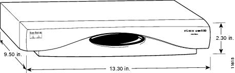
Figure 1-6 Cisco uBR924 Cable Access Router Rear View
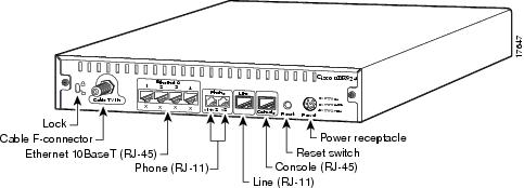
The Cisco uBR924 router is designed to work with commercial security products, such as Kensington-compatible lock and cable devices, that attach to the router to prevent theft in small office applications. The router's rear panel contains generic lock and unlock symbols, identified as "Lock" in Figure 1-6.
Note
The following sections describe the router and its features in more detail:
•
See Appendix B, "Connector and Cable Specifications," for the pinouts and cabling information for each of these connectors. For information on using the console port, see the Cisco uBR924 Software Configuration Guide.
LED Descriptions
The Cisco uBR924 router contains 15 LEDs on the front panel that provide information about the router's status and network connections. Figure 1-7 illustrates the LEDs on the router's front panel. Table 1-1 lists each LED and its meaning.
Note
Figure 1-7 Cisco uBR924 Cable Access Router Front Panel LEDs
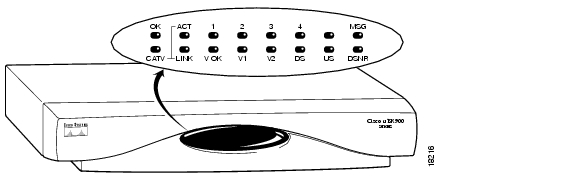
Table 1-1 Cisco uBR924 Cable Access Router Front Panel LED Description
OK
System Status
Green
On = Cisco uBR924 power-on and self-test diagnostics have completed successfully, the system image has been booted, and the system is operational.
Blink = After power-on and self-test diagnostics have completed successfully, LED blinks as the system image is booted.
Off = No Power. If the OK LED turns off and remains off during the boot process, it indicates the router has failed its self-test diagnostics; in this situation the bottom row of LEDs contain more information about the type of failure (see Table 4-1 on page 4-3).
ACT
Cable Activity
Green
On = Cable Activity
Off = No Activity1-4
Ethernet 1-Ethernet 4
Green
On = Link Up
Blink = Activity
Off = Link DownMSG
Message
Green
Reserved for service provider use (typically indicates that messages are waiting in the subscriber's voicemail, but the exact usage depends on the service provider).
V OK
Voice System Status
Green
On = VoIP system is operational
Off = VoIP problem; the voice devices may have switched over to the backup POTS lineV1
Voice Port 1
Green
On = Call in progress
Off = No callV2
Voice Port 2
Green
On = Call in progress
Off = No callLINK
Cable RF Link
Green
On = Cable connection up; RF link up
Blink = Cisco uBR924 is searching for a downstream frequency
Off = Cable connection down; RF link downDS
Downstream Signal Lock Status
Green
On = Cisco uBR924 is locked to a downstream frequency (channel).
Off = Cisco uBR924 has not yet locked to a downstream frequency (channel) or the router has not yet located a digital signal.US
Upstream Signal Quality
Green
On = Cisco uBR924 has established upstream communications with the CMTS; cable access router has completed ranging state 2 (as per DOCSIS), has entered provisioning state, and is communicating within 6 dB of desired final power level (generally within 3 dB).
Off = Cisco uBR924 has not completed secondary ranging; the CMTS has heard from the cable access router, however, and there is some upstream continuity.
DSNR
Downstream Signal-to-Noise Ratio
Green
On = Receiving quality, downstream signal; SNR is greater than 5 dB above the downstream lock threshold.
Off = Receiving low or marginal downstream signal strength or quality.
Note
Data Ports
As shown in Figure 1-6, the Cisco uBR924 cable access router contains a coaxial cable F-connector and four Ethernet 10Base T connectors. The cable F-connector must always be connected to the cable system for proper operation. The Ethernet connectors can be connected in one of the following configurations:
•
•
•
•
Note
Voice Ports
As Figure 1-6 shows, the Cisco uBR924 router contains two FXS VoIP ports that are labelled V1+V2 and V2 at the rear of the unit. These ports can be connected directly to analog telephones or fax devices, or to adapters that allow multiple analog telephones or fax devices to be connected to each of the two VoIP telephone lines.
The V1+V2 port on the Cisco uBR924 is a 4-wire port, with the second telco pair wired in parallel with V2. A two-line analog telephone can be connected, therefore, to the V1+V2 port. In this configuration, devices plugged into the V2 port act as extensions to the line 2 telephone.
Caution
Between 5 and 10 analog telephone devices can be connected to each of the 2 VoIP telephone lines, provided each telephone line does not exceed its Ringer Equivalence Number (REN). In most areas, the sum of the RENs of all devices on any one line should not exceed five. If too many devices are attached, they may not ring properly.
Note
Typical length of telephone wire is 3,000 feet (or more) of 26 gauge. The wiring in the average small business usually does not exceed this limit, so the Cisco uBR924 router can support the number of telephones or fax devices typically found in small businesses.
Backup POTS Connection (RJ-11 Line Connector)
The Cisco uBR924 router provides an RJ-11 cutover port that connects to a standard analog telephone wall jack. In the event of a building power failure or other Cisco uBR924 power problem, this port connects the VoIP ports to the backup PSTN line. If the Cisco uBR924 router loses power while VoIP calls are in progress, the subscriber can re-establish one of the two connections by dialing out over the PSTN.
Note
If power is re-established while a cutover call is in progress, the connection remains in place until the call is terminated. After the cutover call is terminated, the router automatically reboots.
Power Supply
The Cisco uBR924 cable access router uses an external AC-input power supply. Refer to Table A-1 in "Technical Specifications," for the AC-input power supply power specifications, including input voltage and operating frequency ranges.
The Cisco uBR924 cable access router does not contain a power switch. After the cable system technician installs, connects, powers on, and initializes the unit, it is intended to remain connected to the broadband network when operating normally.
The same power supply supports both domestic (U.S.) and international operation. Different power cords are required, however, depending on the country of operation.

Warning
Caution
 Feedback