- Preface
- Chapter 1-Basic Troubleshooting Tasks and Startup Issues
- Chapter 2-PEM Faults and Fan Assembly Failures
- Chapter 3-Troubleshooting PRE Modules
- Chapter 4-Troubleshooting Line Cards and Interface Modules
- Chapter 5-Replacing or Recovering Passwords
- Appendix A Recommended Tools and Test Equipment
Cisco uBR10012 Universal Broadband Router Hardware Troubleshooting Guide for Cisco IOS Release 12.2SC
Bias-Free Language
The documentation set for this product strives to use bias-free language. For the purposes of this documentation set, bias-free is defined as language that does not imply discrimination based on age, disability, gender, racial identity, ethnic identity, sexual orientation, socioeconomic status, and intersectionality. Exceptions may be present in the documentation due to language that is hardcoded in the user interfaces of the product software, language used based on RFP documentation, or language that is used by a referenced third-party product. Learn more about how Cisco is using Inclusive Language.
- Updated:
- March 18, 2015
Chapter: Chapter 2-PEM Faults and Fan Assembly Failures
PEM Faults and Fan Assembly Failures
The following sections provide methods for troubleshooting faults involving the Cisco uBR10012 Power Entry Modules (PEMs), the optional external AC-input power shelf, and fan assembly module. This chapter contains the following major sections:
•![]() External AC-Input Power Shelf
External AC-Input Power Shelf
AC PEM Faults
On the Cisco uBR10012 router, two AC PEMs are installed in a redundant configuration, which allows one AC PEM to fail without affecting system operations. A single PEM can power the router for sufficient time to request and install a new PEM to replace the one that failed.

Tip ![]() To quickly check the functional status of your PEMs, use the show environment command.
To quickly check the functional status of your PEMs, use the show environment command.
AC PEM faults can occur for the following reasons:
•![]() PEM failure
PEM failure
•![]() Invalid AC-input power being supplied by the power source
Invalid AC-input power being supplied by the power source
•![]() Backplane interface failures or damage
Backplane interface failures or damage
Table 2-2 describes the indicators.
Table 2-1 AC PEM LEDs
Table 2-3 lists the AC PEM fault symptoms and corrective actions.
Tip ![]() Securely tighten the captive screws on your PEMs to prevent heightened levels of electromagnetic interference.
Securely tighten the captive screws on your PEMs to prevent heightened levels of electromagnetic interference.
DC PEM Faults
On the Cisco uBR10012 router, two DC PEMs are in a redundant configuration, which allows one DC PEM to fail without affecting system operations. A single PEM can usually power the router for sufficient time to request and install a new PEM to replace the one that failed.
Tip ![]() To quickly check the functional status of your PEMs, use the show environment command.
To quickly check the functional status of your PEMs, use the show environment command.
DC PEM faults can occur for the following reasons:
•![]() PEM failure
PEM failure
•![]() Reversed power cables
Reversed power cables
•![]() Backplane interface failures or damage
Backplane interface failures or damage
Figure 2-1 shows the front panel of the UBR10-PWR-DC Module.
Figure 2-1 Power Entry Module (UBR10-PWR-DC)
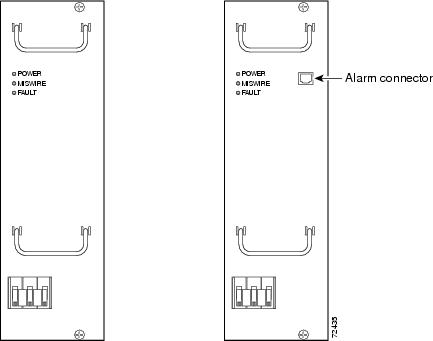
Table 2-5 lists the DC PEM fault symptoms and corrective actions.
Tip ![]() Securely tighten the captive screws on your PEMs to prevent heightened levels of electromagnetic interference.
Securely tighten the captive screws on your PEMs to prevent heightened levels of electromagnetic interference.
External AC-Input Power Shelf
The Cisco uBR10012 Router uses the optional external AC-input power shelves when 100-120 VAC is the only available power source. The AC-input power shelf converts AC power from an external AC power supply source into DC power that is suitable for powering the Cisco uBR10012 router.
2400W AC-Input Power Shelf
The 2400W AC-input power shelf converts AC-output power from an external AC power source into DC power that is suitable for powering the Cisco uBR10012 router. The power shelf supplies -54 VDC output power to the two DC PEMs in the Cisco uBR10012 chassis.
The power shelf includes three 1200-watt (W) AC-input power modules that plug into a common power backplane in the 2400W AC-input power shelf. Two 1200W AC-input power modules are capable of powering a fully configured Cisco uBR10012 router. The third power module provides full redundancy.
During normal operation, the three AC-input power modules provide automatic load-sharing with each power module supporting 33 percent of the power load. When you remove one of the AC-input power modules, the remaining power modules immediately ramp up to full power and maintain uninterrupted system power for a limited time. This allows you to replace the affected module without impacting system operations.

Note ![]() The optional AC-input shelf monitoring cable (UBR10-PWR-MON-CAB=) is used to connect the AC-input power shelf to the DC PEMs. This cable allows the DC PEM to monitor the health of the AC-input power shelf and sends a signal to the IOS whenever there is a failure in one of the AC-input power shelf's power supplies. This cable should be connected to the external alarm connector on the DC PEM if 2400W AC-input power shelf is used. The following PEM status message is observed in the show environment command output: "Power Entry Module 0 type DC status: External AC Supply Fault."
The optional AC-input shelf monitoring cable (UBR10-PWR-MON-CAB=) is used to connect the AC-input power shelf to the DC PEMs. This cable allows the DC PEM to monitor the health of the AC-input power shelf and sends a signal to the IOS whenever there is a failure in one of the AC-input power shelf's power supplies. This cable should be connected to the external alarm connector on the DC PEM if 2400W AC-input power shelf is used. The following PEM status message is observed in the show environment command output: "Power Entry Module 0 type DC status: External AC Supply Fault."
Faults on the 2400W AC-input power shelf can occur for the following reasons:
•![]() The AC-input power to one or more power modules has failed.
The AC-input power to one or more power modules has failed.
•![]() The AC power plug to one or more power modules has been removed or unplugged.
The AC power plug to one or more power modules has been removed or unplugged.
•![]() One or more power modules has failed and must be replaced.
One or more power modules has failed and must be replaced.
For more details on the AC shelf, see the 2400W AC-Input Power Shelf for the Cisco uBR10012 Universal Broadband Router guide.
Other Electrical Problems
If the electrical problem cannot be traced to a PEM, check the unit for:
•![]() Improper power cable connections to the Cisco uBR10012 router
Improper power cable connections to the Cisco uBR10012 router
•![]() Improper installation of other field-replaceable units (FRUs)
Improper installation of other field-replaceable units (FRUs)
Check the site for:
•![]() Improperly grounded equipment, particularly equipment racks and power grounds
Improperly grounded equipment, particularly equipment racks and power grounds
•![]() Fluctuating voltage, which can result from excessive power drains caused by other equipment (such as air conditioning units)
Fluctuating voltage, which can result from excessive power drains caused by other equipment (such as air conditioning units)
•![]() Cable corrosion or defective power panels, circuit breakers or fuses, or cable connections
Cable corrosion or defective power panels, circuit breakers or fuses, or cable connections
•![]() Undersized power cables or excessive power cable lengths
Undersized power cables or excessive power cable lengths
•![]() Excessive power demand on backup power systems or batteries when alternate power sources are used
Excessive power demand on backup power systems or batteries when alternate power sources are used
Fan Assembly Module Faults
The fan assembly module is critical to the operation of the Cisco uBR10012 router because it allows the router to maintain proper operating temperatures. Severe overheating can result in system failure, so a fan assembly module must always be present in the chassis while the router is operating.
Figure 2-2 shows the fan assembly module front panel and its LED indicators.
Figure 2-2 Fan Assembly Module
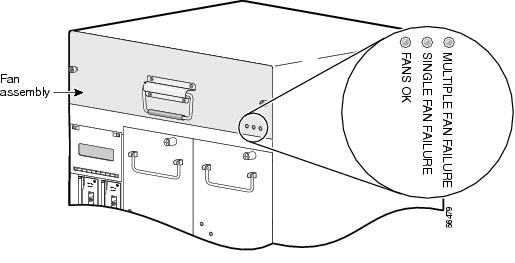
The Cisco uBR10012 fan assembly module contains four fans in a redundant configuration. One fan can fail without affecting system operations. If more than one fan fails, however, the fan assembly module must be replaced immediately to avoid overheating the system.
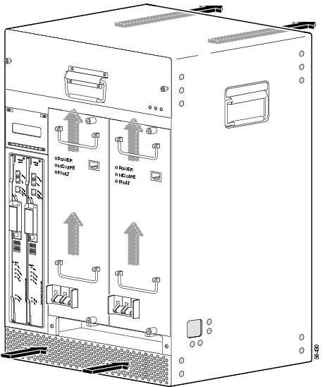
The fan assembly module draws air in from the bottom front of the Cisco uBR10012 router, through the air filter at the bottom of the front bezel. The air is drawn up through the line cards, and then exits through the vents at the top rear of the router.
Figure 2-3 shows the air circulation pattern of the Cisco uBR10012 router when two DC PEMs are installed. The air flow when two AC PEMs are installed is similar. The front bezel is not shown for clarity.
Figure 2-3 Fan Assembly Air Circulation Pattern
The LEDs on the front panel indicate the current status of the fans. Table 2-6 lists the fan assembly module fault indications and recommended actions.
|
|
|
|---|---|
FANS OK LED is not lit |
1. 2. 3. 4. 5. |
SINGLE FAN FAILURE LED is lit |
One fan in the fan assembly module has failed. The fan assembly can cool the chassis sufficiently with three working fans, but replace the failed fan as soon as possible. |
MULTI-FAN FAILURE LED is lit |
More than one fan has failed, and the fan assembly cannot sufficiently cool the chassis. Replace the failed fans immediately. If necessary, power down the chassis until replacements are available. |
Fans run but the system overheats |
1. 2. 3. 4. 5. |
 Feedback