Installing the Power System in the Cisco cBR Chassis
Installing the Power Cassette Module in the Cisco cBR Chassis
The chassis ships with the Power Cassette Module installed. You may need to install the Power Cassette Module to swap the power system of the chassis.
Before you begin
 Warning |
When you install the module, the chassis ground connection must always be made first and disconnected last. Statement 1046 |
-
Be aware of the weight and size of the equipment. Handle it with care.
Required Tools and Equipment
-
3/16" flat-blade torque screwdriver
-
AC or DC Power Cassette Module
-
T10 Torx torque screwdriver
Procedure
| Step 1 |
Loosen the two screws on the front power entry bezel using a 3/16" flat-blade torque screwdriver. Remove the front power entry bezel from the chassis. 
|
||||
| Step 2 |
Remove the four #6-32 Torx-head screws located on the chassis mounting flanges using a T10 Torx torque screwdriver. |
||||
| Step 3 |
Slide the Power Cassette Module into the slot in the chassis until the mounting flanges are fully seated. 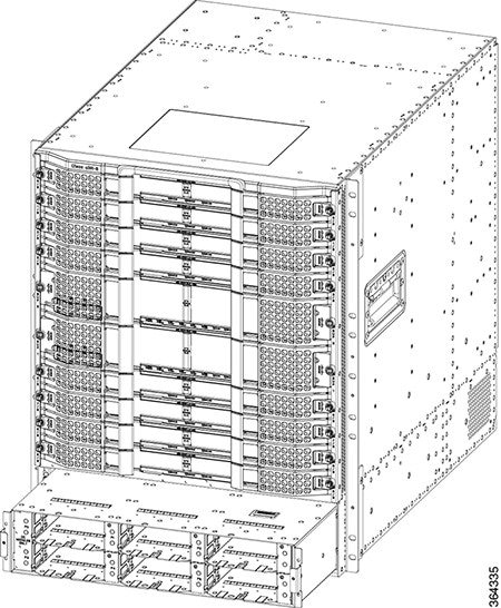 |
||||
| Step 4 |
Insert the four #6-32 Torx-head screws into the mounting flanges. Tighten the screws using a T10 Torx torque screwdriver with a torque of 8-10 in-lb (0.90-1.13Nm) to secure the module. |
||||
| Step 5 |
Position the front power entry bezel on the chassis. Insert and tighten the two screws using a 3/16" flat-blade torque screwdriver with a torque of 5-7 in-lb (0.56-0.79 Nm) to secure the bezel. |
What to do next
Installing the FPEM in the Cisco cBR Chassis
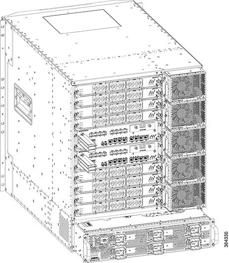
The chassis ships with the FPEM installed. You may need to install the FPEM to swap the power system of the chassis. Use this procedure to install the following modules in the chassis:
-
AC FPEM
-
DC FPEM
Before you begin
-
Attach an ESD-preventive wrist strap to your wrist and connect the other end to the grounding lug connected to the chassis.
-
Be aware of the weight and size of the equipment. Handle it with care.
Required Tools and Equipment
-
ESD-preventive wrist strap
-
AC or DC FPEM
-
T10 Torx torque screwdriver
Procedure
| Step 1 |
Remove the four #6-32 Torx-head screws located on the chassis mounting flanges using a T10 Torx torque screwdriver. |
||
| Step 2 |
Carefully slide the FPEM into the slot using the two handles applying even pressure to both the handles until the FPEM is fully seated in the chassis.
 |
||
| Step 3 |
Insert the four #6-32 Torx-head screws into the mounting flanges. Tighten the screws using a T10 Torx torque screwdriver with a torque of 8-10 in-lb (0.90-1.13Nm) to secure the module. |
What to do next
-
For an AC-powered Cisco cBR chassis, connect the AC power.
For a DC-powered Cisco cBR chassis, connect the DC power.
Installing the Power Module in the Cisco cBR Chassis
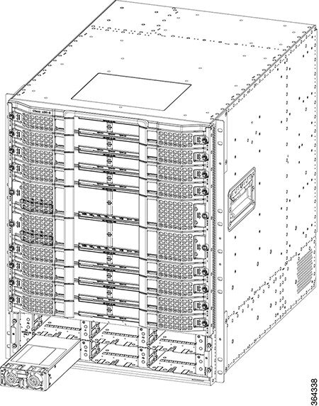
The chassis ships with the Power Module already installed.
Use this procedure to install the following modules in the chassis:
-
AC Power Module
-
DC Power Module
Before you begin
 Important |
We recommend that you wire the chassis for 9 KW of power. If you wire it for less than 9 KW power, you may need to add more power modules while adding new hardware or upgrading the existing hardware. |
Warning |
If you are adding new hardware or upgrading the existing hardware, ensure that the power modules installed in the chassis are adequate to support the hardware. |
-
Attach an ESD-preventive wrist strap to your wrist and connect the other end to the grounding lug connected to the chassis.
-
Be aware of the weight and size of the equipment. Handle it with care.
Required Tools and Equipment
-
ESD-preventive wrist strap
-
3/16" flat-blade torque screwdriver
-
AC or DC Power Module
Procedure
| Step 1 |
Loosen the two screws on the front power entry bezel using a 3/16" flat-blade torque screwdriver. Remove the front power entry bezel from the chassis.
|
||||
| Step 2 |
Carefully slide Power Module into the bay until it mates with the FPEM connectors.
 |
||||
| Step 3 |
Move the handle up to lock the Power Module in the chassis. |
||||
| Step 4 |
Tighten the screw using a 3/16" flat-blade screwdriver with a torque of 5-7 in-lb (0.56-0.79 Nm) to secure the Power Module. |
||||
| Step 5 | |||||
| Step 6 |
Position the front power entry bezel on the chassis. Insert and tighten the two screws using a 3/16" flat-blade torque screwdriver with a torque of 5-7 in-lb (0.56-0.79 Nm) to secure the bezel. |
What to do next
-
For an AC-powered Cisco cBR chassis, connect the AC power.
For an DC-powered Cisco cBR chassis, connect the DC power.
-
If all the interfaces and other cables are connected, power up the Cisco cBR chassis.
-
Verify that the input power LED on the Power Module illuminates green.
Connecting Power to the AC-Powered Cisco cBR Chassis
Warning |
Before connecting AC Power to the AC FPEM, the chassis ground connection must always be made first and disconnected last. |
Warning |
Only trained and qualified personnel should be allowed to install, replace, or service this equipment. Statement 1030 |
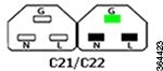
The AC FPEM has six input connectors. Each input connector corresponds to the AC Power Module installed in the front of the chassis. They are IEC60320, C22 inlet connectors, which require facility power cords with a C21 style connector. These are similar to a standard C19/C20 combination, but they have chamfers in the upper corners, which are used to distinguish them as rated for 155C instead of the typical 70C used on the C19/C20.
|
Configuration Female/Male |
Rated Current International |
Rated Current North America |
Wires |
Poles |
Inlet |
Connector |
|---|---|---|---|---|---|---|
 |
250 V 16 A |
125/250 V 16 A |
3 |
2 |
C22 |
C21 |
|
Description |
Value |
|---|---|
|
AC Power Modules per system |
Up to six |
|
Total AC input power per AC Power Module |
3400 VA facility input |
|
Rated input voltage per AC Power Module |
200-240 VAC nominal (range: 180 to 264 VAC) 220-240 VAC (UK) |
|
Rated input line frequency |
50/60 Hz nominal (range: 47 to 63 Hz) 50/60 Hz (UK) |
|
Source AC service requirement |
20 A North America; 16 A international; 13 A UK (IEC60320 C22 connector on the chassis input side) |
Before you begin
Required Tools and Equipment
-
AC power cord
-
#2 Phillips torque screwdriver
Procedure
| Step 1 |
Ensure that the power switch on the AC FPEM is in off (down) position. |
||||
| Step 2 |
Connect the AC power cord to the receptacle on the AC FPEM. 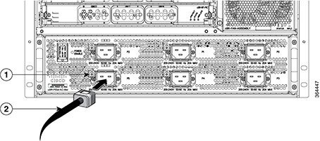
|
||||
| Step 3 |
Tighten the Phillips-head screw on the cable retaining bracket using a #2 Phillips torque screwdriver with a torque of 8-10 in-lb (0.90-1.13Nm). |
||||
| Step 4 |
Connect the other end of the AC power cord to the AC source receptacle. |
||||
| Step 5 |
What to do next
If all the interfaces and other cables are connected, power up the Cisco cBR chassis.
Connecting Power to the DC-Powered Cisco cBR Chassis
Warning |
The terminal block covers are an integral part of the safety design of the product. Do not operate the unit without the covers installed. Statement 1077 |
Warning |
Before connecting DC Power to the DC FPEM, the ground connection must always be made first and disconnected last. |
Warning |
Before performing any of the following procedures, ensure that power is removed from the DC circuit. Statement 1003 |
Warning |
Only trained and qualified personnel should be allowed to install, replace, or service this equipment. Statement 1030 |
The DC FPEM provides terminal blocks for facility input connectivity. It has 12 sets of input terminal blocks to provide each power module with the option of both A and B facility connections.
The table below provides the common input range and circuit breaker requirements:
|
DC Power |
System Input Rating (in A) |
Circuit Breaker (in A) |
AWG # Wire |
||
|---|---|---|---|---|---|
|
Minimum |
Maximum |
Minimum |
Maximum |
||
|
DC FPEM |
2 feeds of 60 A per DC Power Module |
Always 60 |
AWG # 4 or AWG # 6 |
AWG # 21 |
|
Before you begin
-
The color coding of the DC-input power supply leads depends on the color coding of the DC power source at your site. Typically, green or green/yellow is used for ground (GND), black is used for -48V on negative (-) terminal and red is used for RTN on the positive (+) terminal. Ensure that the lead color coding you choose for the DC-input power supply matches lead color coding used at the DC power source.
-
For DC input power cables, select the appropriate wire gauge based on the National Electrical Code (NEC) and local codes for 60-amp service at nominal DC input voltage (-48 VDC). Two pairs of cable leads, source DC (-) and source DC return (+) on P-A and P-B, can be used for each DC Power Module. These cables are available from any commercial cable vendor. All input power cables for the chassis must have the same wire gauge.
Note
You do not need to connect power to both P-A and P-B feeds for each DC Power Module. The DC Power Modules can operate even with one power input connected.
-
Each DC input power cable is terminated at the FPEM by a cable lug (included in the accessory kit). The cable lugs must be dual-hole, and have a 90 degree tongue (reference Panduit LCD4-14AF-L). They must be able to fit over 1/4-20 terminal studs on 0.625 in (15.88 mm) centers and have a maximum tongue width of 0.6 inches.
Note
DC input power cables must be connected to the FPEM terminal studs in the proper positive (+) and negative (-) polarity. Some DC cable leads are labeled, which is a relatively safe indication of the polarity. However, you must verify the polarity by measuring the voltage between the DC cable leads. When measuring the voltage, the positive (+) lead and the negative (-) lead must always match the (+) and (-) labels on the power distribution unit.
-
To avoid hazardous conditions, all components in the area where DC input power is accessible must be properly insulated. Therefore, before installing the DC cable lugs, ensure to insulate the lugs according to the manufacturer's instructions.

Caution
Before installing the DC cable lugs, insulate the entire 90 degree portion of the lugs where the wire is crimped to avoid hazardous conditions where DC input power is accessible through the terminal block cover of the DC FPEM.
Required Tools and Equipment
-
Insulating sleeving
-
Torque wrench
-
7/16" hex socket
-
Lugs for the cables
-
Cables for positive and negative leads
-
Crimping tool
Procedure
| Step 1 |
Ensure that the power switch on the DC FPEM is in off (down) position. |
| Step 2 |
Attach the lug to the lead cable. Carefully crimp the receptacle around the cable using the crimping tool. Insulate the entire 90 degree portion of the lug with shrink sleeving for each lead wire. |
| Step 3 |
Remove the terminal block cover on each terminal block by pushing down on the bottom tab then pivoting the bottom out. 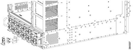 |
| Step 4 |
Loosen the 1/4-20 terminal bolts using a torque wrench and 7/16" hex socket and remove them. |
| Step 5 |
Connect the negative lead cable and secure it in place with the 1/4-20 terminal bolts using a torque wrench and 7/16" hex socket with a torque of 45-50 in-lb (5.08-5.65 Nm). |
| Step 6 |
Connect the positive lead cable and secure it in place with the 1/4-20 terminal bolts using a torque wrench and 7/16" hex socket with a torque of 45-50 in-lb (5.08-5.65 Nm). |
| Step 7 |
Repeat Step 5 and Step 6 for each terminal block connection. |
| Step 8 |
Reinstall the terminal block covers by clipping them on the top edge of the terminal block housing and then rotating them down until they snap into place. |
What to do next
If all the interfaces and other cables are connected, power up the Cisco cBR chassis.
 Feedback