Installing the Fan Module in Cisco cBR
Installing the Fan Module in the cBR Chassis
Before you begin
-
Attach an ESD-preventive wrist strap to your wrist and connect the other end to the grounding lug connected to the chassis.
-
Minimum Keep
Out Areas for Proper Cooling
Air flows from the front to the rear of the chassis. Air enters through the chassis front panel. Additionally, a small air inlet area is on the front right side in front of the mounting ear. Air is expelled from the rear of the chassis and a small exhaust area on the rear left side.
The keep-out areas are defined to ensure adequate space around the Cisco cBR-8 chassis. The space is necessary to ensure adequate air intake and exhaust. The figure shows the keep-out areas for the Cisco cBR-8 chassis.
Figure 1. Keep-Out Areas for the Cisco cBR-8 Chassis 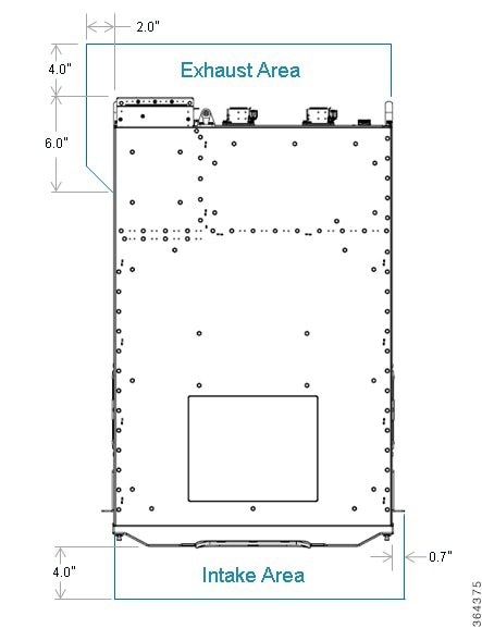
Restrictions
-
Do not boot the chassis unless all the Fan Modules are installed.
-
Only one fan module should be removed at a time for servicing or replacement.
-
Do not operate the chassis with an empty fan bay even if the Supervisor Card allows it.
Required Tools and Equipment
-
Flat-blade torque screwdriver
-
Fan Module (cBR-FAN-ASSEMBLY)
Procedure
| Step 1 |
Using both hands, grip the top and the bottom of the front of the Fan Module. Align the fan module in the chassis slot and push firmly to open hinged door. Continue sliding until the Fan module flanges reach the chassis flange. 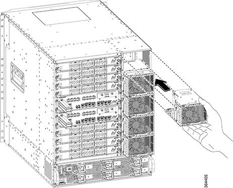 |
||
| Step 2 |
Tighten the captive screws on front left flange of the Fan Module.
|
What to do next
-
Visually check if the fans are working.
-
If the RPLC LED on the Fan Module faceplate is illuminated, see Troubleshooting the Fan Assembly section for corrective action.
 Feedback