Configure Verify Troubleshoot QinQ and L2PT on Catalyst 9000 Switches
Available Languages
Download Options
Bias-Free Language
The documentation set for this product strives to use bias-free language. For the purposes of this documentation set, bias-free is defined as language that does not imply discrimination based on age, disability, gender, racial identity, ethnic identity, sexual orientation, socioeconomic status, and intersectionality. Exceptions may be present in the documentation due to language that is hardcoded in the user interfaces of the product software, language used based on RFP documentation, or language that is used by a referenced third-party product. Learn more about how Cisco is using Inclusive Language.
Contents
Introduction
This document describes how to configure. verify and troubleshoot 802.1Q tunnels (QinQ) and Layer 2 Protocol Tunneling (L2PT) on the Catalyst 9000 family of switches that run Cisco IOS® XE software.
Please refer to the Cisco Official Release Notes and Configuration Guides for up-to-date information about the limitations, restrictions, configuration options, and caveats as well as any other relevant details about this feature.
Prerequisites
Requirements
Cisco recommends that you have knowledge of these topics:
- Catalyst 9000 Series Switches Architecture
- Cisco IOS XE Software Architecture
- Virtual Local Area Networks (VLAN), VLAN trunks, and IEEE 802.1Q encapsulation
- Layer 2 protocols such as Cisco Discovery Protocol (CDP), Link Layer Discovery Protocol (LLDP), Spanning Tree Protocol (STP), Link Aggregation Control Protocol (LACP) and Port Aggregation Protocol (PAgP).
- Basic knowledge of QinQ Tunnels, Selective QinQ Tunnels and Layer 2 Protocol Tunneling (L2PT)
- Switched Port Analyzer (SPAN) and Embedded Packet Captures (EPC)
Components Used
The information in this document is based on these hardware and software versions:
- Cisco Catalyst C9500-12Q with Cisco IOS XE 17.3.3
The information in this document was created from the devices in a specific lab environment. All of the devices used in this document started with a cleared (default) configuration. If your network is live, ensure that you understand the potential impact of any command.
Related Products
This document can also be used with these hardware and software versions:
- Catalyst 3650 and 3850 series switches with Cisco IOS XE software
- Catalyst 9200, 9300, 9400, and 9600 series switches with Cisco IOS XE software
Configure
This section presents a basic topology for IEEE 802.1Q Tunnels (QinQ) deployment on Catalyst 9000 switches, as well as configuration examples for each Catalyst switch.
Network Diagram
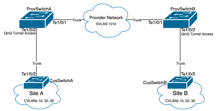
In the topology presented there are two sites, Site A and Site B, which are physically separated by a service provider switched network where Service Virtual LAN (SVLAN) 1010 is used. Provider Edge (PE) switches ProvSwitchA and ProvSwitchB grants access to Site A and Site B, respectively, to the provider network. Site A and Site B uses Customer VLANs (CVLAN) 10, 20 and 30, and require these VLANs to be extended at Layer 2 (L2). Site A connects to the provider network via Customer Edge (CE) switch CusSwitchA and Site B via CE switch CusSwitchB.
Site A sends traffic with the IEEE 802.1Q tag of the CVLAN used, also referred to as inner tag, to the PE switch ProvSwitchA, which acts as a QinQ Tunnel Access. ProvSwitchA forwards the received traffic to the provider switched network with the second IEEE 802.1Q tag of the SVLAN, also referred to as outer tag or Metro tag, added on top of the CVLAN 802.1Q tag. This process is also referred to as VLAN stacks and this example presents a 2-tag VLAN stack. The double-tagged traffic is forwarded by L2 in the provider network based only on SVLAN Media Access Control (MAC) table information. Once the double-tagged traffic arrives at the remote end of the QinQ tunnel, the remote PE switch ProvSwitchB, which also acts as QinQ Tunnel Access, strips off the SVLAN tag from the traffic and forwards it to the Site B tagged only with the CVLAN 802.1Q tag, thus the Layer 2 extension of the VLANs across the remote sites is achieved. L2 Protocols Tunneling is also implemented to exchange Cisco Discovery Protocol (CDP) frames between the CE switches CusSwitchA and CusSwitchB.
This same process happens when traffic is forwarded from Site B to Site A, and the same configuration, verification and steps to troubleshoot apply for PE switch ProvSwitchB. Assume all other devices inside the provider switch network and the Customer sites are only configured with access/trunk commands and do not perform any QinQ function.
The example presented assumes traffic with only one 802.1Q tag is received in the QinQ tunnel access switches, however, traffic received can have zero or more 802.1Q tags. The SVLAN tag is added to the received VLAN stack. No additional QinQ, VLAN, and trunk configurations are required in the devices to support traffic with zero or more 802.1Q tags, however, the Maximum Transmission Unit (MTU) on the devices must be changed to support the additional bytes added to the traffic (additional details described on Troubleshoot section).
Additional information on IEEE 802.1Q Tunnels is presented in the Layer 2 Configuration Guide Document for Catalyst 9500 with Cisco IOS XE Amsterdam-17.3.x:
Configuration on ProvSwitchA (QinQ tunnel PE device):
!
version 17.3
!
hostname ProvSwitchA
!
vtp domain QinQ
vtp mode transparent
!
vlan dot1q tag native
!
vlan 1010
 name QinQ-VLAN
!
interface TenGigabitEthernet1/0/1
 switchport trunk allowed vlan 1010
 switchport mode trunk
!
interface TenGigabitEthernet1/0/2
 switchport access vlan 1010
 switchport mode dot1q-tunnel
 no cdp enable
 l2protocol-tunnel cdp
!
Configuration on ProvSwitchB (QinQ tunnel PE device):
!
version 17.3
!
hostname ProvSwitchB
!
vtp domain QinQ
vtp mode transparent
!
vlan dot1q tag native
!
vlan 1010
 name QinQ-VLAN
!
interface TeGigabitEthernet1/0/1
 switchport trunk allowed vlan 1010
 switchport mode trunk
!
interface TeGigabitEthernet1/0/2
 switchport access vlan 1010
 switchport mode dot1q-tunnel
 no cdp enable
 l2protocol-tunnel cdp
!
Configuration on CusSwitchA (CE device):
!
version 17.3
!
hostname CusSwitchA
!
vtp domain SiteA
vtp mode transparent
!
vlan dot1q tag native
!
vlan 10
 name Data
!
vlan 20
 name Voice
!
vlan 30
 name Mgmt
!
interface TenGigabitEthernet1/0/2
 switchport trunk allowed vlan 10,20,30
 switchport mode trunk
!
Configuration on CusSwitchB (CE device):
!
version 17.3
!
hostname CusSwitchB
!
vtp domain SiteB
vtp mode transparent
!
vlan dot1q tag native
!
vlan 10
 name Data
!
vlan 20
 name Voice
!
vlan 30
 name Mgmt
!
interface TenGigabitEthernet1/0/2
switchport trunk allowed vlan 10,20,30
switchport mode trunk
!
Notice that the CVLANs are not defined in the provider devices, and SVLAN is not defined on the CE switches. The provider devices forward traffic based on SVLAN only and do not consider the CVLAN information for any forward decision, therefore it is not required for a provider device to know which VLANs are received in a QinQ tunnel access (unless Selective QinQ is used). This also means the same VLAN IDs used for the CVLAN tags can be used for traffic within the provider switched network and viceversa. If this is the case, the recommendation is to configure vlan dot1q tag native on Global Configuration mode to prevent any packet loss or traffic leak issue. The vlan dot1q tag native enables 802.1Q native VLAN to be tagged on all trunk interfaces by default, but this can be disabled at the interface level with no switchport trunk native vlan tag configuration.
Verify
Port configuration for QinQ tunnels and L2PT can be verified from Cisco IOS XE perspective to the Forwarding Application-Specific Integrated Circuit (FWD-ASIC) perspective, where the forward decisions on a Catalyst switch occur. The basic Cisco IOS XE verification commands are:
- show dot1q-tunnel - Lists the interfaces configured as QinQ tunnel access.
ProvSwitchA# show dot1q-tunnel
dot1q-tunnel mode LAN Port(s)
-----------------------------
Te1/0/2
- show vlan id {svlan-number} - Displays the interfaces assigned to the specified VLAN.
ProvSwitchA# show vlan id 1010
VLAN Name                             Status    Ports
---- -------------------------------- --------- -------------------------------
1010 QinQ-VLAN                        active    Te1/0/1, Te1/0/2
- show interfaces trunk - Lists the interfaces configured in trunk mode.
ProvSwitchA# show interfaces trunk
Port           Mode             Encapsulation  Status        Native vlan
Te1/0/1        on               802.1q         trunking      1

Port           Vlans allowed on trunk
Te1/0/1        1010
- show vlan dot1q tag native - Lists the 802.1Q native VLAN tag global status, and trunk interfaces configured to tag 802.1Q native VLAN.
ProvSwitchA# show vlan dot1q tag native
dot1q native vlan tagging is enabled globally
Per Port Native Vlan Tagging State
----------------------------------
Port         Operational        Native VLAN
                Mode            Tagging State
-------------------------------------------
Te1/0/1      trunk                 enabled
- show mac address-table vlan {svlan-number} - Shows MAC addresses learned in the SVLAN. MAC addresses from LAN devices are learned in the SVLAN regardless of the CVLAN used.
ProvSwitchA#show mac address-table vlan 1010
          Mac Address Table
-------------------------------------------
Vlan    Mac Address       Type        Ports
----    -----------       --------    -----
1010    701f.539a.fe46    DYNAMIC     Te1/0/2
Total Mac Addresses for this criterion: 3
- show l2-protocol tunnel - Shows interface enabled for L2PT and counters for each of the enabled L2 protocols.
ProvSwitchA#show l2protocol-tunnel
COS for Encapsulated Packets: 5
Drop Threshold for Encapsulated Packets: 0

Port                Protocol    Shutdown  Drop      Encaps    Decaps  Drop
                                Threshold Threshold Counter   Counter Counter
------------------- ----------- --------- --------- --------- --------- ---------
Te1/0/2             cdp         ----      ----      90        97        0
                    ---         ----      ----      ----      ----      ----
- show cdp neighbor - Can be run on CE switches to confirm they can see each other via CDP.
CusSwitcha#show cdp neighbors
Capability Codes: R - Router, T - Trans Bridge, B - Source Route Bridge
S - Switch, H - Host, I - IGMP, r - Repeater, P - Phone,
D - Remote, C - CVTA, M - Two-port Mac Relay

Device ID Local       Intrfce   Holdtme Capability Platform  Port ID
CusSwitchB.cisco.com  Ten 1/0/2 145     S I        C9500-12  Ten 1/0/2
When an interface is configured as a QinQ tunnel access via Command Line Interfaces (CLI), the Cisco IOS XE triggers the Port Manager (PM) process to configure the switchports with the mode and VLAN specified. Switchport information can be checked in PM with the show pm port interface {interface-name} command.
Note: In order to run PM commands, it is required to configure the service internal on Global Configuration mode. This configuration enables additional platform and debug commands to be run on the CLI, and has no functional impact on the network. It is recommended to remove this command once the PM verification is completed.
ProvSwitchA# show pm port interface TenGigabitEthernet1/0/2
port 1/2  pd 0x7F9E317C3A48 swidb 0x7F9E30851320(switch)  sb 0x7F9E30852FE8
if_number = 2 hw_if_index = 1 snmp_if_index = 2(2) ptrunkgroup = 0(port)
admin up(up)  line up(up)  operErr none
port assigned mac address 00a3.d144.200a
idb port vlan id 1010  default vlan id 1010
speed: 10G   duplex: full   mode: tunnel   encap: native
flowcontrol receive: on   flowcontrol send: off

sm(pm_port 1/2), running yes, state dot1qtunnel
The interface Te1/0/2 is assigned the interface number (if_number) of 2. This is the Interface Identifier (IF-ID), the internal value that identifies a specific port. The switchport configuration can also be verified on PM with the show platform software pm-port switch 1 R0 interface {IF-ID} command.
ProvSwitchA# show platform software pm-port switch 1 R0 interface 2
PM PORT Data:

Intf	PORT	DEFAULT	NATIVE	ALLOW	MODE	PORT	PORT
ID	ENABLE	VLAN	VLAN	NATIVE		DUPLEX	SPEED
---------------------------------------------------------
2	TRUE	1010	1010	TRUE	tunnel	full	unknown
Once PM applies the switchport configuration, PM relays the port information to the Forwarding Engine Driver (FED) in order to program the Application-specific Integrated Circuits (ASIC) accordingly.
In FED, ports can be checked with the show platform software fed switch {switch-number} port if_id {IF-ID} command to confirm they are programmed as QinQ tunnel access ports:
ProvSwitchA# show platform software fed switch 1 port if_id 2
FED PM SUB PORT Data :
  if_id = 2
  if_name = TenGigabitEthernet1/0/2
  enable: true
  speed: 10Gbps
  operational speed: 10Gbps
  duplex: full
  operational duplex: full
  flowctrl: on
  link state: UP
  defaultVlan: 1010
  port_state: Fed PM port ready
  mode: tunnel
Unlike switchports in access mode, which expect to receive only untagged traffic, a switchport configured in 802.1Q tunnel mode accepts traffic with 802.1Q tags too. FED allows this feature on the port for QinQ tunnel access ports, as can be confirmed with the show platform software fed switch {switch-number} ifm if-id {IF-ID}:
C9500-12Q-PE1# show platform software fed switch 1 ifm if-id 2
Interface Name          : TenGigabitEthernet1/0/2
Interface State         : Enabled
Interface Type          : ETHER
	Port Type         : SWITCH PORT
	Port Location     : LOCAL
	Port Information
	Type .............. [Layer2]
	Identifier ........ [0x9]
	Slot .............. [1]
	Port Physical Subblock
		Asic Instance ..... [0 (A:0,C:0)]
		Speed ............. [10GB]
		PORT_LE ........... [0x7fa164777618]
	Port L2 Subblock
		Enabled ............. [Yes]
		Allow dot1q ......... [Yes]
                Allow native ........ [Yes]
		Default VLAN ........ [1010]
		Allow priority tag ... [Yes]
		Allow unknown unicast  [Yes]
		Allow unknown multicast[Yes]
		Allow unknown broadcast[Yes]
FED also provides a handle value in a hexadecimal format called Port Logical Entity (Port LE). The Port LE is a pointer to the port information programmed in the Forwarding ASIC (fwd-asic). The show platform hardware fed switch 1 fwd-asic abstraction print-resource-handle {Port-LE-handle} 1 command displays the different features enabled on the port at ASIC level:
C9500-12Q-PE1# show platform hardware fed switch 1 fwd-asic abstraction print-resource-handle 0x7f79548c3718 1

Detailed Resource Information (ASIC_INSTANCE# 0)
----------------------------------------
LEAD_PORT_ALLOW_BROADCAST value 1 Pass
LEAD_PORT_ALLOW_DOT1Q_TAGGED value 1 Pass
LEAD_PORT_ALLOW_MULTICAST value 1 Pass
LEAD_PORT_ALLOW_NATIVE value 1 Pass
LEAD_PORT_ALLOW_UNICAST value 1 Pass
LEAD_PORT_ALLOW_UNKNOWN_UNICAST value 1 Pass¡
LEAD_PORT_SEL_QINQ_ENABLED value 0 Pass
LEAD_PORT_DEFAULT_VLAN value 1010 Pass
==============================================================
This output confirms at the ASIC level that the QinQ tunnel access switchport is configured to allow untagged and 802.1Q tagged traffic from the LAN, and assign SVLAN 1010 to be forwarded across the provider switched network. Notice that the LEAD_PORT_SEL_QINQ_ENABLED field is unset. This bit is set for Selective QinQ configuration only, not for traditional QinQ tunnels configuration as presented in this document.
Troubleshoot
This section provides the steps you can follow to troubleshoot your configuration. The most useful tool to troubleshoot traffic issues in an 802.1Q tunnel is Switched Port Analyzer (SPAN). SPAN captures can be used to verify the 802.1Q tag of the CVLAN received from the LAN and SVLAN added in the QinQ tunnel access device.
Note: Embedded Packet Captures (EPC) can also be used to capture traffic in an 802.1Q tunnel environment. However, egress packet captures with EPC occur before the traffic is tagged with IEEE 802.1Q (802.1Q tag insertion occurs at the port level in egress direction). In consequence, egress EPC on the provider-edge device's uplink trunk is not able to display the SVLAN tag used in the provider switched network. An option to collect the double-tagged traffic with EPC is to capture the traffic with ingress EPC on the neighbor provider device.
Refer to the Network Management Configuration Guide for Catalyst 9500 switches with Cisco IOS XE Amsterdam-17.3.x for additional information on EPC:
https://www.cisco.com/c/en/us/td/docs/switches/lan/catalyst9500/software/release/17-3/configuration_guide/nmgmt/b_173_nmgmt_9500_cg/configuring_packet_capture.html
To configure SPAN to capture traffic with 802.1Q tags, it is important to configure the monitor session {session-number} destination interface {interface-name} encapsulation replicate command. If the encapsulation replicate keyword is not configured, the traffic mirrored with SPAN might contain incorrect 802.1Q tags information. Refer to the Configure section for an example of the SPAN configuration.
For additional information on SPAN, please refer to the Network Management Configuration Guide for Catalyst 9500 switches with Cisco IOS XE Amsterdam-17.3.x
SPAN configuration example on ProvSwitchA:
!
monitor session 1 source interface Te1/0/1 , Te1/0/2
monitor session 1 destination interface Te1/0/3 encapsulation replicate
!
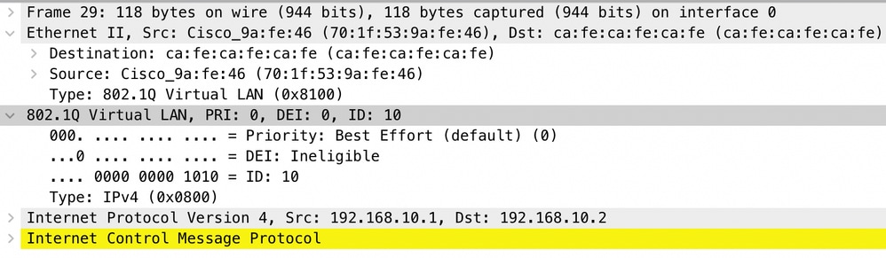
In the Network Analyzer device, the received mirrored traffic can be reviewed to confirm the presence of CVLAN 10 in the QinQ tunnel access ingress:
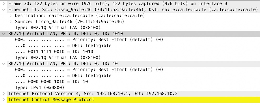
Similarly, the presence of both CVLAN 10 and SVLAN 1010 can be confirmed in the egress direction in the interface trunk connected to the provider switched network.
Note: Certain Network Interface Cards (NIC) on Network Analyzers can remove 802.1Q tags on tagged traffic received. Please contact support the NIC vendor for specific information on how to maintain the 802.1Q tags on received frames.
If traffic loss in the QinQ switched network is suspected, consider these items to review:
- Default Maximum Transmission Unit (MTU) on a trunked interface is 1522 bytes. This accounts for the IP MTU of 1500, the Ethernet header frame of 18 bytes, and one 802.1Q tag of 4 bytes. Configured MTU in all provider and provider edge devices must have 4 additional bytes per 802.1Q tag added in the VLAN stack. For example, for a 2-tag VLAN stack, an MTU of 1504 must be configured. For a 3-tag VLAN stack, an MTU of 1508 must be configured, and so on. Refer to the Interface and Hardware Components Configuration Guide for Catalyst 9500 with Cisco IOS XE Amsterdam-17.3.x for MTU configuration details: https://www.cisco.com/c/en/us/td/docs/switches/lan/catalyst9500/software/release/17-3/configuration_guide/int_hw/b_173_int_and_hw_9500_cg/configuring_system_mtu.html
- Traffic punt to the CPU on devices inside an 802.1Q tunnel is not supported. Features that require traffic inspection can cause packet loss or packet leaks in an 802.1Q environment. Examples of these features are DHCP Snooping for DHCP traffic, IGMP Snooping for IGMP traffic, MLD Snooping for MLD traffic and Dynamic ARP Inspection for ARP traffic. It is recommended to disable these features on the SVLAN used to transport traffic through the provider switched network.
Additional debug commands
Note: Refer to Important Information on Debug Commands before you use debug commands.
- debug pm port - Displays Port Manager (PM) port transitions and programmed mode. Useful to debug QinQ port configuration status.
Related Information
Revision History
| Revision | Publish Date | Comments |
|---|---|---|
2.0 |
15-Mar-2022 |
Removed unnecessary words from title. |
1.0 |
08-Mar-2022 |
Initial Release |
Contributed by Cisco Engineers
- Jason BabbTAC Engineer
- Camilo HernandezTAC Engineer
 Feedback
Contact Cisco
- Open a Support Case

- (Requires a Cisco Service Contract)