CS-MARS - Add and Configure an IPS Sensor as a Reporting Device
Available Languages
Contents
Introduction
This document explains how to prepare a Cisco Secure Intrusion Prevention System (IPS) device and any configured virtual sensors to act as a reporting devices to Cisco Security Monitoring, Analysis, and Response System (CS-MARS).
Prerequisites
Requirements
For Cisco IPS 5.x, 6.x, and 7.x devices, MARS pulls the logs using SDEE over SSL. Therefore, MARS must have HTTPS access to the sensor. In order to prepare the sensor, you must enable the HTTP server on the sensor, enable TLS to allow HTTPS access, and make sure that the IP address of MARS is defined as an allowed host, one that can access the sensor and pull events. If the sensors have been configured to allow access from limited hosts or subnets on the network, you can use the access-list ip_address/netmask command in order to enable this access.
Components Used
The information in this document is based on these software and hardware versions:
-
Cisco Secure MARS Device that runs software version 4.2.x and later
-
Cisco 4200 Series IPS Device that runs software version 6.0 and later
The information in this document was created from the devices in a specific lab environment. All of the devices used in this document started with a cleared (default) configuration. If your network is live, make sure that you understand the potential impact of any command.
Related Products
This configuration can also be used with these sensors:
-
IPS-4240
-
IPS-4255
-
IPS-4260
-
IPS-4270-20
Conventions
Refer to the Cisco Technical Tips Conventions for more information on document conventions.
Configure
In this section, you are presented with the information on how to add and configure a Cisco Secure Intrusion Prevention System (IPS) sensor to a Cisco Security Monitoring, Analysis, and Response System (CS-MARS) device.
Add and Configure a Cisco IPS 6.x or 7.x Device in MARS
When you define a Cisco IPS 6.x or 7.x device in MARS, you can discover any virtual sensors configured on the device. When you discover these virtual sensors, this allows MARS to separate the reported events by virtual sensor. It also allows you to tune the list of monitored networks to each virtual sensor, which improves the accuracy of the desired reporting.
Complete these steps in order to add and configure a Cisco IPS 6.x or 7.x device in MARS:
-
Choose Admin > System Setup > Security and Monitor Devices. Then, click on Add.
-
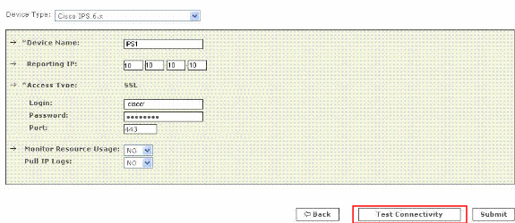
Choose Cisco IPS 6.x or Cisco IPS 7.x from the Device Type list. Now enter the hostname of the sensor in the Device Name field as shown here. IPS1 is the Device Name used in this example. The Device Name value must be identical to the configured sensor name.
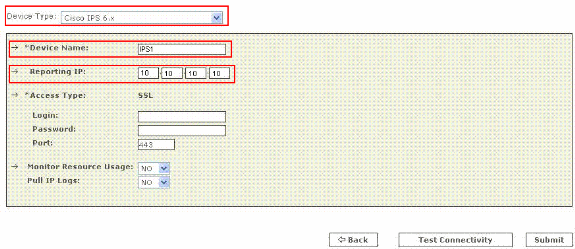
Now enter the administrative IP address in the Reporting IP field. The Reporting IP address is the same address as the administrative IP address.
-
In the Login field, enter the username associated with the administrative account that is used to access the reporting device. Now, in the Password field, enter the password associated with the username specified in the Login field. The username is cisco and the password used is cisco123 in this example. Also enter the TCP port number on which the webserver running on the sensor listens in the Port field. The default HTTPS port is 443.
Note: While it is possible to configure HTTP only, MARS requires HTTPS.
-
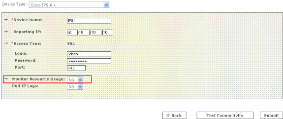
Now verify that NO is chosed in the Monitor Resource Usage list. While the Monitor Resource Usage option appears on this page, it does not function for Cisco IPS.
-
In order to pull the IP logs from the sensor, choose Yes from the Pull IP Logs list. This is an optional feature, which can be used if required.
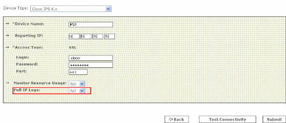
This setting applies to the entire sensor, which includes those logs generated for virtual sensors alerts.
-
Click Test Connectivity in order to verify the configuration and enable the discovery of virtual sensors.
-
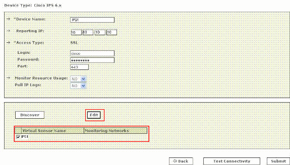
Click Discover in order to discover any defined virtual sensors.
Note: MARS is unaware of changes made to the sensor. Anytime you make changes to the virtual sensor settings, you must click Discover on that sensor configuration page in order to refresh the virtual sensor details in MARS.
-
Choose the checkbox next to the Virtual Sensor Name and click Edit in order to define the monitored networks for each virtual sensor. Now the IPS Module page appears as shown here.
-
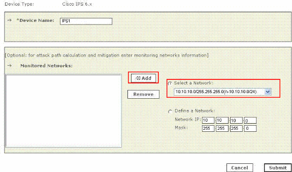
For attack path calculation and mitigation, specify the networks being monitored by the sensor. Choose the Define a Network radio button in order to manually define the network. Then complete these steps in order to define a Network:
-
Enter the network address in the Network IP field.
-
Enter the corresponding network mask value in the Mask field.
-
Click Add in order to move the specified network into the Monitored Networks field.
-
Repeat the previous steps if there is a need to define more networks.

Note: This is an optional feature available and can be skipped if not required.
-
-
Click the Select a Network radio button in order select the networks that are attached to the device. Then complete these steps in order to choose the networks:
-
Choose a network from the Select a Network list.
-
Click Add in order to move the specified network into the Monitored Networks field.
-
Repeat the previous steps if there is a need to choose more networks.
Note: This is an optional feature available and can be skipped if not required.
-
-
Repeat step 8 through step 10 for each virtual sensor.
-
Click Submit in order to save your changes. The device name appears under the Security and Monitoring Information list. The submit operation records the changes in the database tables. But, it does not load the changes into working memory of the MARS Appliance. The activate operation loads submitted changes into working memory.
-
Click Activate in order to enable MARS to start to sessionize events from this device.
MARS begins to sessionize events generated by this module and evaluate those events using the defined inspection and drop rules. Any events published by the device to MARS before activation can be queried with the reporting IP address of the device as a match criterion. Refer to Activate the Reporting and Mitigation Devices. for more information on the activate action.


Verify that MARS Pulls Events from a Cisco IPS Device
It is common to create benign events on the network in order to verify the data flow. Complete these steps in order to verify the data flow between a Cisco IPS device and MARS:
-
On the Cisco IPS device, enable and alert on the signatures 2000 and 2004. The signatures monitor ICMP messages (pings).
-
Ping a device on the subnet on which the Cisco IPS device is listening. The events are generated and pulled by MARS.
-
Verify that the events appear in the MARS web interface. You can perform a query with the Cisco IPS device.
-
Once the dataflow is verified, you can disable the 2000 and 2004 signatures on the Cisco IPS device.
Note: If the Test Connectivity operation does not fail during the configuration of a Cisco IPS device in the MARS web interface, then communications are enabled. This task allows you to further verify the alerts are generated and pulled correctly.
Troubleshoot
There is currently no specific troubleshooting information available for this configuration.
Related Information
Revision History
| Revision | Publish Date | Comments |
|---|---|---|
1.0 |
01-Dec-2013 |
Initial Release |
 Feedback
Contact Cisco
- Open a Support Case

- (Requires a Cisco Service Contract)