Setting up Shunning on a UNIX Director
Available Languages
Contents
Introduction
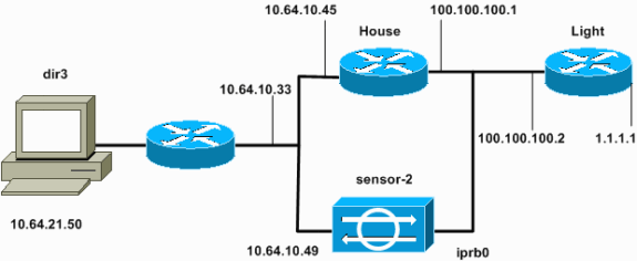
Cisco Intrusion Detection System (IDS) Director and Sensor can be used to manage a Cisco router for shunning. In this document, a Sensor (sensor-2) is configured in order to detect attacks on the router "House" and in order to communicate this information to the Director "dir3." Once configured, an attack is launched (ping of larger than 1024 bytes, which is signature 2151, and an Internet Control Message Protocol [ICMP] flood, which is signature 2152) from router "Light." The Sensor detects the attack and communicates this to the Director. An Access Control List (ACL) is downloaded to the router to shun traffic from the attacker. On the attacker host unreachable is shown, and on the victim the downloaded ACL is shown.
Prerequisites
Requirements
Before you attempt this configuration, ensure that you meet these requirements:
-
Install the Sensor and make sure it works properly.
-
Ensure that the sniffing interface spans to the router's outside interface.
Components Used
The information in this document is based on these software and hardware versions:
-
Cisco IDS Director 2.2.3
-
Cisco IDS Sensor 3.0.5
-
Cisco IOS® router with 12.2.6
The information in this document was created from the devices in a specific lab environment. All of the devices used in this document started with a cleared (default) configuration. If your network is live, make sure that you understand the potential impact of any command.
Conventions
For more information on document conventions, refer to the Cisco Technical Tips Conventions.
Configure
In this section, you are presented with the information to configure the features described in this document.
Note: To find additional information on the commands used in this document, use the Command Lookup Tool (registered customers only) .
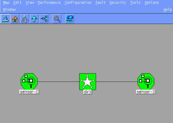
Network Diagram
This document uses the network setup shown in this diagram.
Configurations
This document uses these configurations.
| Router Light |
|---|
Current configuration : 906 bytes ! version 12.2 service timestamps debug uptime service timestamps log uptime no service password-encryption ! hostname light ! enable password cisco ! username cisco password 0 cisco ip subnet-zero ! ! ! ip ssh time-out 120 ip ssh authentication-retries 3 ! call rsvp-sync ! ! ! fax interface-type modem mta receive maximum-recipients 0 ! controller E1 2/0 ! ! ! interface FastEthernet0/0 ip address 100.100.100.2 255.255.255.0 duplex auto speed auto ! interface FastEthernet0/1 ip address 1.1.1.1 255.255.255.0 duplex auto speed auto ! ip classless ip route 0.0.0.0 0.0.0.0 100.100.100.1 ip http server ip pim bidir-enable ! ! dial-peer cor custom ! ! line con 0 line 97 108 line aux 0 line vty 0 4 login ! end |
| Router House |
|---|
Current configuration : 2187 bytes ! version 12.2 service timestamps debug uptime service timestamps log uptime no service password-encryption ! hostname house ! enable password cisco ! ! ! ip subnet-zero ! ! fax interface-type modem mta receive maximum-recipients 0 ! ! ! ! interface FastEthernet0/0 ip address 100.100.100.1 255.255.255.0 !--- After you configure shunning, IDS Sensor puts this line in. ip access-group IDS_FastEthernet0/0_in_1 in duplex auto speed auto ! interface FastEthernet0/1 ip address 10.64.10.45 255.255.255.224 duplex auto speed auto ! ! ! interface FastEthernet4/0 no ip address shutdown duplex auto speed auto ! ip classless ip route 0.0.0.0 0.0.0.0 10.64.10.33 ip route 1.1.1.0 255.255.255.0 100.100.100.2 ip http server ip pim bidir-enable ! ! !--- After you configure shunning, IDS Sensor puts these lines in. ip access-list extended IDS_FastEthernet0/0_in deny ip host 100.100.100.2 any permit ip host 10.64.10.49 any permit ip any any ! snmp-server manager ! call RSVP-sync ! ! mgcp profile default ! dial-peer cor custom ! ! ! ! line con 0 line aux 0 line vty 0 4 password cisco login ! ! end house# |
Configure the Sensor
Complete these steps to configure the Sensor.
-
Telnet to 10.64.10.49 with username root and password attack.
-
Enter sysconfig-sensor.
-
When prompted, enter the configuration information, as shown in this example.
1 - IP Address: 10.64.10.49 2 - IP Netmask: 255.255.255.224 3 - IP Host Name: sensor-2 4 - Default Route 10.64.10.33 5 - Network Access Control 64. 10. 6 - Communications Infrastructure Sensor Host ID: 49 Sensor Organization ID: 900 Sensor Host Name: sensor-2 Sensor Organization Name: cisco Sensor IP Address: 10.64.10.49 IDS Manager Host ID: 50 IDS Manager Organization ID: 900 IDS Manager Host Name: dir3 IDS Manager Organization Name: cisco IDS Manager IP Address: 10.64.21.50 -
When prompted, save the configuration and allow the Sensor to reboot.
Add the Sensor into the Director
Complete these steps to add the Sensor into the Director.
-
Telnet to 10.64.21.50 with username netrangr and password attack.
-
Enter ovw& to launch HP OpenView.
-
In the Main Menu, select Security > Configure.
-
In the Configuration File Management Utility, select File > Add Host, and click Next.
-
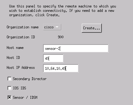
This is an example of how to fill out the requested information.
-
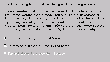
Accept the default setting for the type of machine, and click Next, as shown in this example.
-
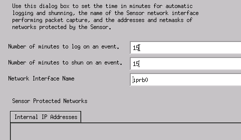
Change the log and shun minutes, or leave them as the default if the values are acceptable. Change the network interface name to the name of your sniffing interface.
In this example it is "iprb0." It can be "spwr0" or anything else depending on the Sensor type and how you connect your Sensor.
-
Click Next until there is an option to click Finish.
You have successfully added the Sensor into Director. From the Main Menu, you should see sensor-2, as in this example.


Configure Shunning for the Cisco IOS Router
Complete these steps to configure shunning for the Cisco IOS router.
-
In the Main Menu, select Security > Configure.
-
In the Configuration File Management Utility, highlight sensor-2 and double click it.
-
Open Device Management.
-
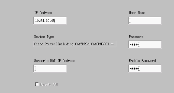
Click Devices > Add, and enter the information as shown in this example. Click OK to continue.
The Telnet and enable passwords match what is in the router "House."
-
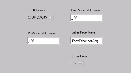
Click Interfaces > Add, enter this information, and click OK to continue.
-
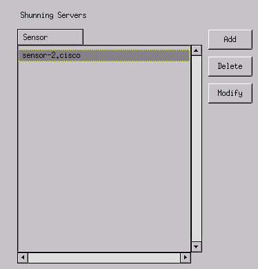
Click Shunning > Add and select sensor-2.cisco as the shunning server. Close the Device Management window when you are finished.
-
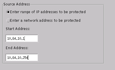
Open the Intrusion Detection window, and click Protected Networks. Add the range 10.64.10.1 to 10.64.10.254 into the protected network, as shown in this example.
-
Click Profile > Manual Configuration.
-
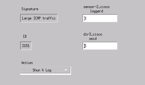
Select Modify Signatures > Large ICMP Traffic with an ID of 2151.
-
Click Modify, change the Action from None to Shun & Log, and click OK to continue.
-
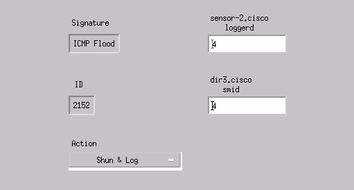
Choose ICMP Flood with an ID of 2152, and click Modify. Change the Action from None to Shun & Log, and click OK to continue.
-
Click OK to close the Intrusion Detection window.
-
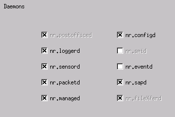
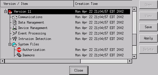
Open the System Files folder, and open the Daemons window.
Make sure you have enabled these daemons:
-
Click OK to continue, choose the version just modified, and click Save and then Apply.
Wait for the system to tell you the Sensor finished restarting services, then close all the windows for the Director Configuration.


Verify
This section provides information you can use to confirm your configuration is working properly.
Certain show commands are supported by the Output Interpreter Tool (registered customers only) , which allows you to view an analysis of show command output.
-
show access-list - Lists the access-list command statements in the router configuration. It also lists a hit count that indicates the number of times an element has been matched during an access-list command search.
-
ping - Used to diagnose basic network connectivity.
Before an Attack is Launched
Before an attack is launched, issue these commands.
house#show access-list
Extended IP access list IDS_FastEthernet0/0_in_1
    permit ip host 10.64.10.49 any
    permit ip any any (12 matches)
house#

light#ping 10.64.10.45

Type escape sequence to abort.
Sending 5, 100-byte ICMP Echos to 10.64.10.45, timeout is 2 seconds:
!!!!!
Success rate is 100 percent (5/5), round-trip min/avg/max = 1/1/4 ms
light#
Launch the Attack and Shunning
Launch your attack from the router "Light" to the victim "House." When the ACL takes affect, the unreachables are seen.
light#ping
Protocol [ip]:
Target IP address: 10.64.10.45
Repeat count [5]: 1000000
Datagram size [100]: 18000
Timeout in seconds [2]:
Extended commands [n]:
Sweep range of sizes [n]:
Type escape sequence to abort.
Sending 1000000, 18000-byte ICMP Echos to 10.64.10.45, timeout is 2 seconds:
!!!!!!!!!!!!!!!!!!!!!!!!!!!!!!!!!!!!!!!!!!!!!!!!!!!!!!!!!!!!!!!!!!!!!!
!!!!!!!!!!!!!!!!!!!!!!!!!!!!!!!!!!!!!!!!!!!!!!!!!!!!!!!!!!!!!!!!!!!!!!
!!!!!!!!!!!!!!U.U.U.U.U.U.U.U.U.U.U.U.U.U.U.U.U.
Once the Sensor has detected the attack, and the ACL is downloaded, and this output is displayed on "House."
house#show access-list
Extended IP access list IDS_FastEthernet0/0_in_0
  permit ip host 10.64.10.49 any
  deny ip host 100.100.100.2 any (459 matches)
  permit ip any any
The unreachables are still seen on "Light," as shown in this example.
Light#ping 10.64.10.45
Type escape sequence to abort.
Sending 5, 100-byte ICMP Echos to 10.64.10.45, timeout is 2 seconds:
U.U.U
Success rate is 0 percent (0/5)
Fifteen Minutes later, "House" goes back to normal, because shunning was set to 15 minutes.
House#show access-list
Extended IP access list IDS_FastEthernet0/0_in_1
    permit ip host 10.64.10.49 any
    permit ip any any (12 matches)
house#
"Light" can ping "House."
Light#ping 10.64.10.45

Type escape sequence to abort.
Sending 5, 100-byte ICMP Echos to 10.64.10.45, timeout is 2 seconds:
!!!!!
Success rate is 100 percent (5/5), round-trip min/avg/max = 1/1/4 ms
Troubleshoot
There is currently no specific troubleshooting information available for this configuration.
Related Information
Revision History
| Revision | Publish Date | Comments |
|---|---|---|
1.0 |
05-Sep-2001 |
Initial Release |
 Feedback
Contact Cisco
- Open a Support Case

- (Requires a Cisco Service Contract)